Smeva Vision MKII Installation guide

Installation, operating and maintenance manual
Vision MKII
Smeva BV
Visiting address: J.F. Kennedylaan 27
5555 XC Valkenswaard
Telephone: +31 40 20 73 200
Internet: www.smeva.com
Specifications for the manual: Date: December 2015
Version: 1.0

Scope of delivery &
copyright Vision MKII
1
Scope of delivery & copyright
The installation, operating and maintenance manual is part of this product. It must always be kept
near the product. Following the instructions in this manual is a requirement for correct use of the
product. The user manual corresponds to the product as constructed and meets all applicable
safety-related standards.
The product consists of the following components:
Vision refrigerated display case for fresh products
Vision refrigerated display case for packaged products
Built-in control panel
Optional OEM control panel.
Optional ultrasonic humidifier
Optional reverse osmosis filter
Optional fish display case
Optional micro-misting
Accessories
Copyright
This manual is a publication of Smeva BV Valkenswaard, The Netherlands.
No part of this publication (including translations) may be reproduced in part or as a whole, stored
in an electronic retrieval system, or transmitted in any form or by any means, including
photocopying, microfilm, or otherwise, without the prior written permission of the publisher.
The manuals reflect the most recent product developments at the time of printing.
We reserve the right to make changes at any time, both to the technical specifications and
construction.
© Smeva BV, The Netherlands. Printed in the Netherlands.

Scope of delivery &
copyright Vision MKII
2
Overview Vision MKII display case for fresh products, KU flat
glass (top
-
hinged)
1. Skirting board
2. Front panel (S)
3. Front consumer side
4. Bumper rail
5. Cold plate (presentation surface)
6. Night cover
7. Discharge grille
8. Intake grille
9. Fan
10. Work surface
11. Product identification label
12. Cooled evaporator
13. Distribution pipe, ultrasonic mister
14. Thermostat control and switches, rear panel
15. Mains socket rail
16. Switch box, optional location of built-in machine / open storage
17. Service panel
18. Lighting profile, presentation surface
19. Air guide partition
Vision MKII KU with light

Scope of delivery &
copyright Vision MKII
3
Overview Vision
MKII display case for fresh products, RO curved glass (top
-
hinged)
1. Skirting board
2. Front panel (S)
3. Front consumer side
4. Price card rail / label holder
5. Cold plate (presentation surface)
6. Night cover
7. Discharge grille
8. Intake grille
9. Fan
10. Work surface
11. Product identification label
12. Cooled evaporator
13. Distribution pipe, ultrasonic mister
14. Thermostat control and switches, rear panel
15. Mains socket rail
16. Switch box, optional location of built-in machine / open storage
17. Service panel
18. Lighting profile, presentation surface

Scope of delivery &
copyright Vision MKII
4
Overview Vision MKII Panorama display case for fresh products, PA UV
-
bonded glass
(bottom-hinged)
1. Skirting board
2. Front panel (S)
3. Front consumer side
4. Price card rail / label holder
5. Cold plate (presentation surface)
6. Night cover
7. Discharge grille
8. Intake grille
9. Fan
10. Work surface
11. Product identification label
12. Cooled evaporator
13. Distribution pipe, ultrasonic mister
14. Thermostat control and switches, rear panel
15. Mains socket rail
16. Switch box, optional location of built-in machine / open storage
17. Service panel
Vision MKII Panorama A

Scope of delivery &
copyright Vision MKII
5
Overview Vision MKII display case for packaged products, KU
-
SP, flat self
-
service glass
1. Skirting board
2. Front panel (S)
3. Front consumer side
4. Price card rail / label holder
5. Intake grille
6. Product stop
7. Cold shelf (presentation surface)
8. Night cover
9. Fan
10. Heater, electric defroster
11. Discharge grille
12. Work surface
13. Product identification label
14. Cooled evaporator
15. Thermostat control and switches, rear panel
16. Mains socket rail
17. Switch box, optional location of built-in machine / open storage
18. Service panel

Contents Vision MKII
6
Contents
SCOPE OF DELIVERY & COPYRIGHT .............................................................................................................. 1
CONTENTS ............................................................................................................................................................ 6
EXTERNAL DOCUMENTS ................................................................................................................................... 7
SAFETY .................................................................................................................................................................. 8
1 INTRODUCTION .............................................................................................................................................. 11
2 TRANSPORT & INSTALLATION ..................................................................................................................... 12
3 GUIDELINES FOR USE ................................................................................................................................... 26
4 CLEANING & MAINTENANCE ........................................................................................................................ 37
5 END OF LIFE, DISASSEMBLY & DISPOSAL ................................................................................................ 46
6 TROUBLESHOOTING ..................................................................................................................................... 47
7 PRODUCT IDENTIFICATION .......................................................................................................................... 48

External documents Vision MKII
7
External documents
External documentation
•Data sheet
•Electrical wiring diagram
•Refrigeration system diagram
•Floor plan
•Optional items
The external documentation is available on request from your Smeva partner.

Safety Vision MKII
8
Safety
This user manual contains the basic guidelines that must be followed during use and operation of
the product. The user must therefore read and fully understand the user manual before the
product is put in use. Not only must the general safety instructions be followed, but the specific
safety instructions below, indicated by a danger symbol, must also be respected.
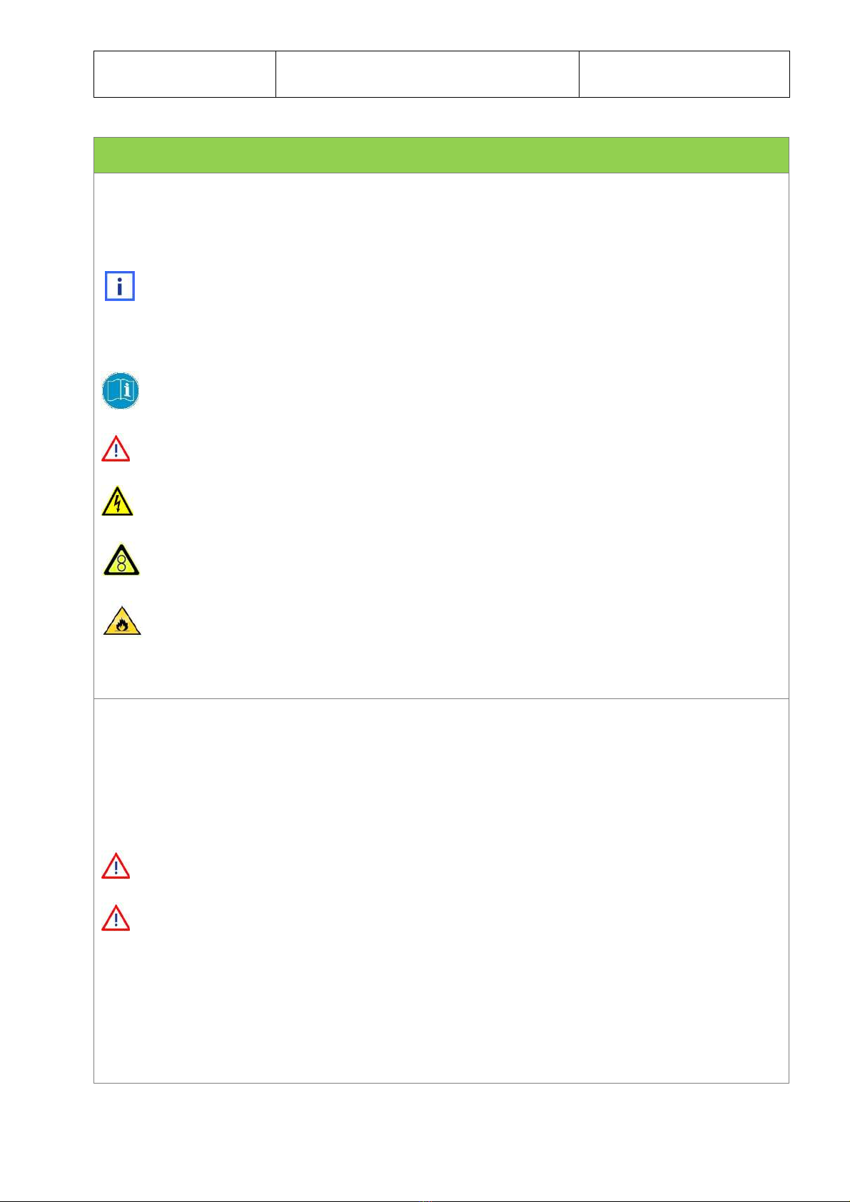
The following stickers are found on the equipment:
•Warning stickers
•Product identification sticker & CE (see Chapter 7, Product identification)
This sticker indicates that you must consult the manual.
General warning symbol.
Danger due to electric voltage.
Danger due to moving parts.
Fire hazard.
Warnings
Failure to observe the safety instructions and comply with the safety guidelines can result in
situations that are hazardous to people and may cause damage to the product. Failure to comply
with the safety guidelines can lead to loss of the right to compensation for damages and may void
the warranty. More specifically, failure to comply with the safety guidelines may result in dangers,
such as: Failure of important product functions, danger to people in connection with electrical
and/or mechanical operation, and/or property damage.
Do not remove the stickers from the display appliance.
Glass panels:
During opening and cleaning only grasp the top edge of the glass panels, not the sides;
otherwise you put yourself at risk of pinching/crushing. Open the glass panel completely to
prevent it from falling closed.
Open one glass panel at a time, and close it again before you open another one.
Due to the low visibility of the glass, do not leave the display appliance unattended with
the glass panel in the open position; employees and customers might walk into it.

Safety Vision MKII
9
Maximum load.
Do not place weight on any surface of the display case that exceeds the maximum weight
limit. Never exceed the maximum load. (See Chapter 3, Guidelines for use).
Fall hazard.
Never climb in or on the display case.
Electrical hazard:
All the electrical parts are located outside of the ‘wet’ working area.
Mains sockets, control panel and main switch are located on the serving side.
The electrical connection box and devices are located on the serving side, behind the
service panel.
Danger due to moving parts:
Fan present near the evaporator. Danger of injury on contact. Hair and clothing becoming
entangled in the fan.
Fire hazard:
The integrated condensers (if present) contain flammable refrigerant.
Follow the instructions on the label to prevent risk of fire in the event of a refrigerant leak in
the display case.
Cleaning:
Before cleaning the presentation surface always switch off the refrigeration system
at the control panel.

Safety Vision MKII
10
The presentation surface of display cases with a non-removable cold plate must be
cleaned with soap and lots of water. Never spray water on the electrical parts beyond this
surface.
- The control panels
- The mains sockets
- The fans
- The anti-condensation nose fans (hidden behind the nose profile)
- The lighting
- The technical areas located under the display appliance and behind the service panel.

1 Introduction Vision MKII
11
1 Introduction
You made a good decision when you purchased the Vision display case for fresh product
presentation from Smeva.
The Vision display cases are specially designed for the refrigerated presentation of fresh
products. For the presentation of products with more stacking height there is also a display case
with forced air cooling available, suitable for the presentation of packaged products. This optional
display case is also delivered with a low glass panel for self-service.
Technical characteristics of the Vision series:
•The display case can be built with various temperature zones.
•The presentation surface is made of polished 304 stainless steel.
•The presentation surface is non-removable, refrigerated and slightly angled for easy
cleaning and draining toward the serving side. An easily accessible trough with drain is
located behind the discharge grilles for the cooled air.
•Optional ultrasonic humidifier for fresh products. The water supply for the humidifier is
filtered with a reverse osmosis filter.
•Optional fish tray for presentation of fresh fish on crushed ice.
•Optional micro-misting for fresh fish. The water supply for the micro-misting is filtered with
a reverse osmosis filter.
This manual describes the correct use of your Vision display case, which is guaranteed by
Smeva for quality, reliability and use of the latest technological developments.
As owner and/or HACPP manager you are legally required to document the maintenance
of the display case. For the purposes of product liability and warranty you are required to have
your display case inspected annually by an authorized technician. See also Chapter 4,
Cleaning and maintenance.
As an extra service, a brief troubleshooting guide is enclosed, which can be used to
resolve simple, minor malfunctions. For more complicated malfunctions and/or defects of the
display appliance you must contact your Smeva partner.

2 Transport &
installation Vision MKII
12
2 Transport & installation
Shipping
The display case is packed in plastic film for
transport. The edges and corners are also
protected with hard foam or corrugated cardboard.
To the extent possible, all parts and options have
been preinstalled at the factory.
Depending on the type of glass panels, the
glass is supported with wooden beams or the
glass has been removed to prevent damage
during transport. The glass at the ends has
also been removed.
Inspect all parts immediately at the time of
delivery. Document all irregularities in
writing. Always contact the Smeva partner
responsible for the product.
All material for installation and all
accessories are located in the display case
or are preinstalled. Contact your Smeva
partner if anything is missing, before you
complete the installation.

2 Transport &
installation Vision MKII
13
Photo of transport beam (consumer side).
Transport at location.
The display case is delivered in straight and
corner sections up to 7.5 m in length with
transport beams. The figure shows the position of
one of the transport beams, as seen from the front
side.
Lifting of the display case must be done
with lifting equipment that is carefully inserted
between the wooden transport beams and
beneath the steel profiles, carefully balanced
in the centre of the length and weight of the
display case.
The total weight of the display case is
shown on the Vision data sheet.
Insert the forklift fork completely, under the
steel profiles at the front and back.
Make sure none of the display case parts or
electrical cables are hanging loose and
become pinched between the fork and the
display case.
Wooden
beams

2 Transport &
installation Vision MKII
14
Photo of transport beam on serving side, with the
single screw in the metal frame visible.
Placement
See the floorplan for the correct
dimensions.
Make sure the cables and pipes coming
out of the floor do not become pinched under
the display case.
The wooden transport beam can be
detached by removing a single screw from the
serving side of the display case (see figure) and
using a hammer carefully, if the beam is stuck.
Phillips screwdriver
Hammer
Levelling
Level the display case and adjust it to the correct
height using the adjustable feet.
Place the skirting board stand-offs under
the adjustable feet before you level the display
case.
17 mm spanner
Spirit level
Spirit level
Adjustable foot

2 Transport &
installation Vision MKII
15
Removing the front panels
1. Lift up the panel.
2. Pull the panel toward you.
3. Pull the panel down until the top side
detaches.

2 Transport &
installation Vision MKII
16
Rinse water and hygienic sealing of display
case joints
Apply caulk between the PU foam parts:
1. Apply a full bead of caulk to the top side
(position: 1).
2. On the inside (position: 2) apply caulk in a
vertical pattern to prevent entrapment of
air bubbles.
3. Join the two display case sections
together.
4. Remove the excess caulk.
Use soapy water to form a smooth,
continuous caulk surface.
Apply the caulk before the display cases are
joined together. The application of caulk after
joining will result in leakage.
Any excess caulk must be removed before
the protective film is removed from the stainless
steel presentation surface.
Caulk: (included)
A) Shell
B) Frame
C) Stainless steel presentation
surface
D) Connection plate
E) Caulk
F) Tape

2 Transport &
installation Vision MKII
17
Vision Curved
Glass
Vision Cube
Assembly of joined display case sections
Joining is accomplished with threaded rods in the
frame (1).
Align the aluminium nose profiles with round keys
(2).
Aligned
Threaded rods and M8 bolts (included)
Round keys (included)
ø4 x2 4mm
2 2
1
Vision Panorama

2 Transport &
installation Vision MKII
18
Alignment of work surface with flat or square
keys
Align the stainless steel work surface with the two
extending joining brackets (pos. 4) and screws
(pos. 3).
Aligned
Joining bracket for stainless steel work
surface (3, 4 included)
Alignment of lighting profiles
Align the aluminium lighting profiles with round
keys and flat joining plate.
1. round key
2. flat screw
3. plate
4. nuts
Aligned
Allen wrench
Open-end spanner

2 Transport &
installation Vision MKII
19
Alignment of bumper rail or bag
bench holder
Align the bumper rail or bag bench with the
appropriate keys.
Aligned
Square or round bumper rail and bag
bench holder: keys (included)
Stainless steel bag bench holder: bolts
(included)
Connecting electrical wiring between display
cases
Electrical connection is made by connecting the
prepared plugs and mating plugs under the
various display cases.
Sensor
s
Mains sockets
Display cas
e
Table of contents