Smith MaxiVac MV-360 Guide
3A5576
EN
Operation, Parts
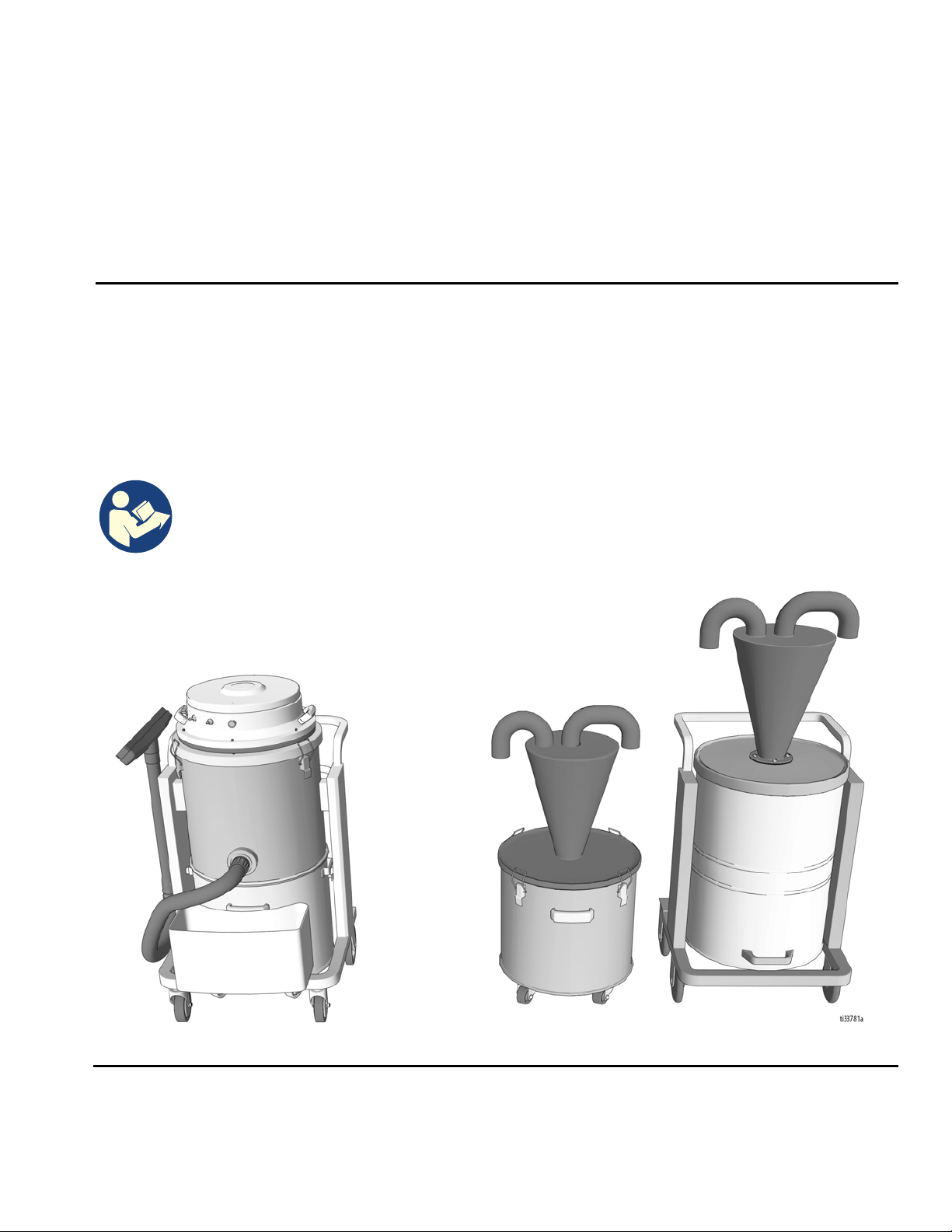
MaxiVac™and Cyclones
Vacuum for collection of dry concrete and asphalt dust. For professional use only.
Vacuums
Model MV-360 (120V)
Model MV-600 (230V)
Separators
Model MV-SA (20 gallon)
Model MV-SB (32 gallon)
Important Safety Instructions
Read all warnings and instructions in this manual.
Be familiar with the controls and the proper usage
of the equipment. Save all instructions.
MaxiVac MV-SA and MV-SB

Contents
2TBD
Contents
Warnings . . . . . . . . . . . . . . . . . . . . . . . . . . . . . . . . . . . . . . . . . . . . . . . . . . . . . . . . . . . . . . . . . . . . . . . . . . . . . . .3
Component Identification . . . . . . . . . . . . . . . . . . . . . . . . . . . . . . . . . . . . . . . . . . . . . . . . . . . . . . . . . . . . . . . . . .6
MV-360 and 330 . . . . . . . . . . . . . . . . . . . . . . . . . . . . . . . . . . . . . . . . . . . . . . . . . . . . . . . . . . . . . . . . . . . . . . .6
MV-SA . . . . . . . . . . . . . . . . . . . . . . . . . . . . . . . . . . . . . . . . . . . . . . . . . . . . . . . . . . . . . . . . . . . . . . . . . . . . . . .6
MV-SB . . . . . . . . . . . . . . . . . . . . . . . . . . . . . . . . . . . . . . . . . . . . . . . . . . . . . . . . . . . . . . . . . . . . . . . . . . . . . . .6
Setup . . . . . . . . . . . . . . . . . . . . . . . . . . . . . . . . . . . . . . . . . . . . . . . . . . . . . . . . . . . . . . . . . . . . . . . . . . . . . . . . . . .7
Operation . . . . . . . . . . . . . . . . . . . . . . . . . . . . . . . . . . . . . . . . . . . . . . . . . . . . . . . . . . . . . . . . . . . . . . . . . . . . . . .8
Emptying Collection Tanks . . . . . . . . . . . . . . . . . . . . . . . . . . . . . . . . . . . . . . . . . . . . . . . . . . . . . . . . . . . . . . .8
Shutdown and Storage . . . . . . . . . . . . . . . . . . . . . . . . . . . . . . . . . . . . . . . . . . . . . . . . . . . . . . . . . . . . . . . . . . . .9
Shutdown . . . . . . . . . . . . . . . . . . . . . . . . . . . . . . . . . . . . . . . . . . . . . . . . . . . . . . . . . . . . . . . . . . . . . . . . . . . .9
Storage . . . . . . . . . . . . . . . . . . . . . . . . . . . . . . . . . . . . . . . . . . . . . . . . . . . . . . . . . . . . . . . . . . . . . . . . . . . . . .9
Maintenance . . . . . . . . . . . . . . . . . . . . . . . . . . . . . . . . . . . . . . . . . . . . . . . . . . . . . . . . . . . . . . . . . . . . . . . . . . . .10
Parts . . . . . . . . . . . . . . . . . . . . . . . . . . . . . . . . . . . . . . . . . . . . . . . . . . . . . . . . . . . . . . . . . . . . . . . . . . . . . . . . . .11
Main Assembly Diagram (MaxiVac) . . . . . . . . . . . . . . . . . . . . . . . . . . . . . . . . . . . . . . . . . . . . . . . . . . . . . . . 11
Main MaxiVac Assembly Parts (MaxiVac) . . . . . . . . . . . . . . . . . . . . . . . . . . . . . . . . . . . . . . . . . . . . . . . . . . .12
Motor Housing Assembly Diagram (MV-360) . . . . . . . . . . . . . . . . . . . . . . . . . . . . . . . . . . . . . . . . . . . . . . . .13
Motor Housing Assembly Parts List (MV-360) . . . . . . . . . . . . . . . . . . . . . . . . . . . . . . . . . . . . . . . . . . . . . . . .14
Motor Housing Assembly Diagram (MV-600) . . . . . . . . . . . . . . . . . . . . . . . . . . . . . . . . . . . . . . . . . . . . . . . .15
Motor Housing Assembly Parts List (MV-600) . . . . . . . . . . . . . . . . . . . . . . . . . . . . . . . . . . . . . . . . . . . . . . . .16
Auto Filter Cleaner Assembly (MaxiVac) . . . . . . . . . . . . . . . . . . . . . . . . . . . . . . . . . . . . . . . . . . . . . . . . . . . .17
MV-SA Assembly and Accessories . . . . . . . . . . . . . . . . . . . . . . . . . . . . . . . . . . . . . . . . . . . . . . . . . . . . . . . .18
MV-SA Assembly and Accessories Parts List . . . . . . . . . . . . . . . . . . . . . . . . . . . . . . . . . . . . . . . . . . . . . . . .19
MV-SB Assembly and Accessories . . . . . . . . . . . . . . . . . . . . . . . . . . . . . . . . . . . . . . . . . . . . . . . . . . . . . . . .20
MV-SB Assembly and Accessories Parts List . . . . . . . . . . . . . . . . . . . . . . . . . . . . . . . . . . . . . . . . . . . . . . . .21
Technical Data . . . . . . . . . . . . . . . . . . . . . . . . . . . . . . . . . . . . . . . . . . . . . . . . . . . . . . . . . . . . . . . . . . . . . . . . . .22
SMITH Standard Warranty . . . . . . . . . . . . . . . . . . . . . . . . . . . . . . . . . . . . . . . . . . . . . . . . . . . . . . . . . . . . . . . .23
Warnings
TBD 3
Warnings
The following warnings are for the setup, use, grounding, maintenance, and repair of this equipment. The exclamation
point symbol alerts you to a general warning and the hazard symbols refer to procedure-specific risks. When these
symbols appear in the body of this manual or on warning labels, refer back to these Warnings. Product-specific hazard
symbols and warnings not covered in this section may appear throughout the body of this manual where applicable.
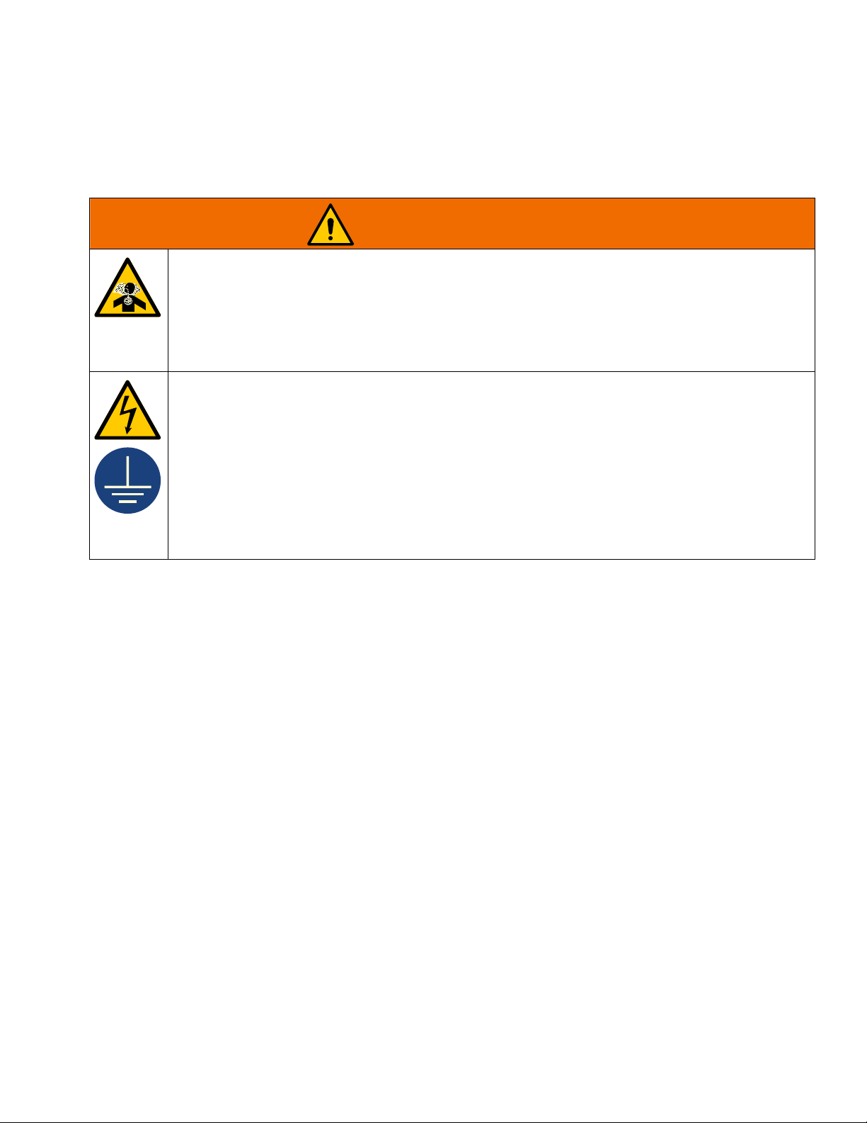
WARNING
DUST HAZARD
Grinding concrete and other surfaces can create dust that contains hazardous substances.
To reduce the risk of serious injury:
• Control the dust to meet all applicable workplace regulations.
• Wear a properly fit-tested and government approved respirator suitable for the dust conditions when
emptying collection tank or performing maintenance.
• Do not use without dust bag and filters in place.
ELECTRIC SHOCK HAZARD
This equipment must be grounded. Improper grounding, setup, or usage of the system can cause elec-
tric shock.
• Turn off and disconnect power cord before servicing equipment.
• Connect only to grounded electrical outlets.
• Use only 3-wire extension cords.
• Ensure ground prongs are intact on power and extension cords.
• Do not expose to rain. Store indoors.
• Do not abuse the cord. Never use the cord for carrying, pulling or unplugging the equipment. Keep
cord away from heat, sharp edges, or moving parts.
• Do not use on wet surfaces.

Warnings
4TBD
GROUNDING
This product must be grounded. In the event of an electrical short circuit, grounding reduces the risk of
electric shock by providing an escape wire for the electric current. This product is equipped with a cord
having a grounding wire with an appropriate grounding plug. The plug must be plugged into an outlet
that is properly installed and grounded in accordance with all local codes and ordinances.
• Improper installation of the grounding plug is able to result in a risk of electric shock.
• When repair or replacement of the cord or plug is required, do not connect the grounding wire to
either flat blade terminal.
• The wire with insulation having an outer surface that is green with or without yellow stripes is the
grounding wire.
• Check with a qualified electrician or serviceman when the grounding instructions are not completely
understood, or when in doubt as to whether the product is properly grounded.
• Do not modify the plug provided; if it does not fit the outlet, have the proper outlet installed by a
qualified electrician.
• This product is for use on a nominal 120V or 230V circuit and has a grounding plug similar to the
plugs illustrated in the figure below.
• Only connect the product to an outlet having the same configuration as the plug.
• Do not use an adapter with this product.
Extension Cords:
• Use only a 3-wire extension cord that has a grounding plug and a grounding receptacle that
accepts the plug on the product.
• Make sure your extension cord is not damaged. If an extension cord is necessary, use 12 AWG
(2.5 mm2) minimum to carry the current that the product draws.
• An undersized cord results in a drop in line voltage and loss of power and overheating.
WARNING
120V US 230V

Warnings
TBD 5
EQUIPMENT MISUSE HAZARD
Misuse can cause death or serious injury.
• Do not operate the unit when fatigued or under the influence of drugs or alcohol.
• Do not leave the work area while equipment is energized. Turn off all equipment when equipment is
not in use.
• Check equipment daily. Repair or replace worn or damaged parts immediately with genuine
manufacturer’s replacement parts only.
• Do not alter or modify equipment.
• Use equipment only for its intended purpose. Call your distributor for information.
• Keep children and animals away from work area.
• Comply with all applicable safety regulations.
• Maintain a safe operating distance from other people in the work area.
ENTANGLEMENT HAZARD
Rotating parts can cause serious injury.
• Keep clear of moving parts.
• Do not operate equipment with protective guards or covers removed.
• Do not wear loose clothing, jewelery, or long hair while operating equipment.
FIRE AND EXPLOSION HAZARD
Flammable fumes in work area can ignite or explode. To help prevent fire and explosion:
• Do not use to pick up flammable or combustible liquids, such as gasoline, or use in areas where they
may be present.
PERSONAL PROTECTIVE EQUIPMENT
You must wear appropriate protective equipment when operating, servicing, or when in the operating
area of the equipment to help protect you from serious injury, inhalation of dust or chemicals, and
hearing loss. This equipment includes but is not limited to:
• Protective eye wear.
• Hearing protection.
• Properly fit-tested and government approved respirator suitable for the dust conditions.
WARNING

Component Identification
6TBD
Component Identification
MV-360 and 330 MV-SA MV-SB
Component
A Auto Filter Cleaner Power Switch
B Vacuum Motor Switch
C Vacuum Motor Switch
D Vacuum Motor Switch (MV-600 only)
E Motor Housing Assembly
F Engagement Lever
G Filter Housing and Body
H Dust Collection Tank
J Vacuum Hookup
K Vacuum Inlet
L Vacuum Outlet
N Separator Lid
O Long Hose
P Short Hose
Setup
TBD 7
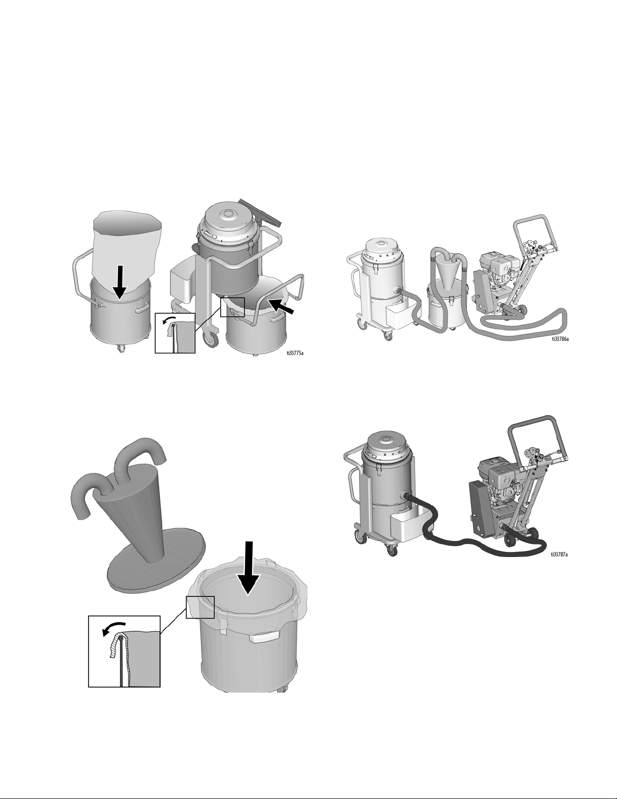
Setup
1. Insert dust collection bags into Dust Collection
Tan k s.
a. Remove Dust Collection Tank by pulling up on
the Engagement Lever and insert the collection
bag into the tank. Wrap the bag around the lip of
the tank and reinsert the tank into the bottom of
the MaxiVac. Lock the tank by pushing down on
the Engagement Lever.
b. If using a Cyclone separator, remove the
Separator Lid and insert the collection bag into
the tank. Wrap the bag around the lip of the tank
and reinstall the Separator lid onto the tank.
2. Connect hoses.
If using a Cyclone separator:
• Connect one end of the short vacuum hose to the
inlet of the MaxiVac. Connect the other end of the
short hose to the outlet of the Cyclone separator.
• Connect one end of the Long Vacuum Hose to the
inlet of the Cyclone separator. Connect the other
end of the long hose to the vacuum hookup on the
GrindLazer.
If not using a Cyclone separator:
• Connect one end of the Long Vacuum Hose to the
inlet of the MaxiVac. Connect the other end of the
long hose to the vacuum hookup on the GrindLazer.
Operation
8TBD
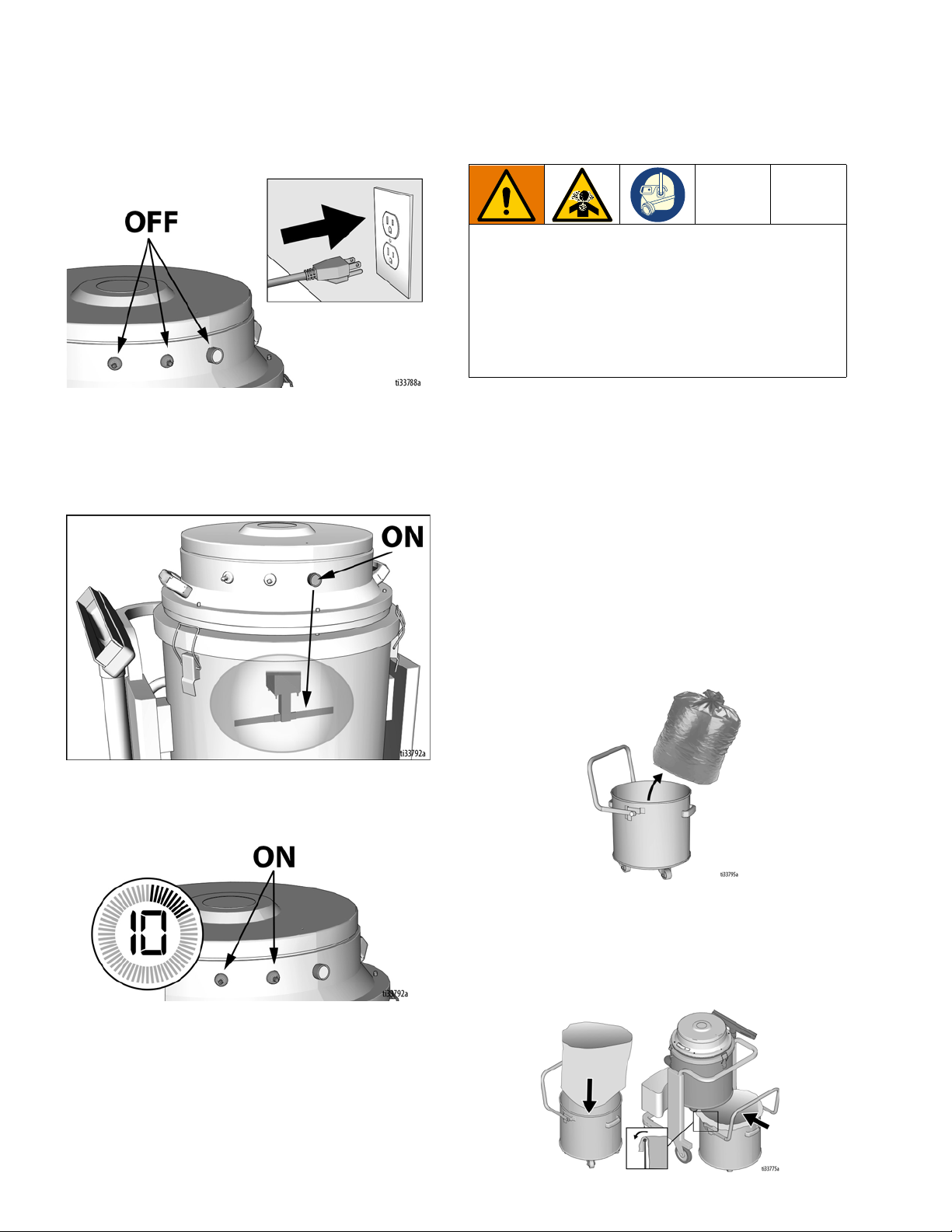
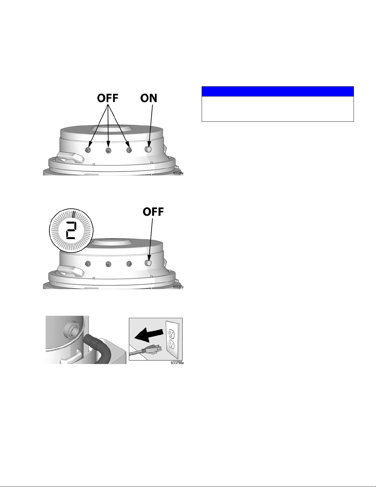
Operation
1. Ensure MaxiVac motor switches are turned to
“OFF”. Plug vacuum into grounded power source.
2. Turn Auto Filter Cleaner Power Switch to “ON”.
Ensure the sound of the Filter Cleaner Bar is heard
contacting the inside of the filter. If no sound is
heard, replace the Plastic Inserts on the cleaning
bar. See page 17.
3. After 10 seconds, turn on a Vacuum Motor Switch.
Turn on additional vacuum motors if needed.
4. MaxiVac is now ready for dust collection from the
GrindLazer or other removal equipment.
Emptying Collection Tanks
1. When Dust Collection Tanks are full, turn off all
vacuum motors. Turn Auto Filter Cleaner power
switch to “ON”. After 2 minutes of cleaning the
vacuum filters, turn off cleaning switch and unplug
vacuum from power source.
2. If MaxiVac is full, remove Dust Collection Tank by
pulling up on the Engagement Lever.
3. If Cyclone separator is full, remove the Separator
Lid.
4. Wearing a respirator, gather and secure the top of
the collection bag. Lift and remove the collection
bag, tie up and then dispose. Follow local
ordinances and regulations for disposal.
5. Insert new bags into the collection tanks and
reinsert the tanks into the Cyclone separator and
into the bottom of the MaxiVac. Ensure the Dust
Collection Tank is securely attached to the body of
the vacuum by pushing down on the Engagement
Lever.
DUST HAZARD
Grinding concrete and other surfaces can create dust
that contains hazardous substances. To reduce the
risk of serious injury:
• Respirator must be worn when emptying or
cleaning Dust Collection Tanks or bags.
• Follow local ordinances and regulations for
disposal.
Shutdown and Storage
TBD 9
Shutdown and Storage
Shutdown
1. Turn off all vacuum motors and leave Auto Filter
Cleaner Power Switch to ON.
2. Allow the Auto Filter Cleaner to run for 2 minutes,
then turn to OFF.
3. Unplug MaxiVac from power source and remove
hoses from the vacuum.
Storage
Disconnect power cord before storing. Store indoors.
NOTICE
Do not store in a location with high temperatures or
excessive humidity, in order to prevent damage to
your MaxiVac components.

Maintenance
10 TBD
Maintenance
The following steps should be performed to maintain
proper operation and sustain the life of the MaxiVac.
Daily
• Prior to use, inspect all hoses for holes. Repair or
replace damaged hoses.
• To help maintain performance and dust control,
replace filters when:
- Vacuum filters have tears or are clogged.
- Airborne dust is visible when using the
MaxiVac.
Weekly
• Inspect Filter Ring Seal for damage. If damaged,
replace seal. Ensure seals are installed correctly
and properly sealed.
• Inspect Filter Cleaner Plastic Inserts for wear or
damage. Replace the inserts regularly to help
maintain performance and dust control.
DUST AND SHOCK HAZARD
To reduce the risk of serious injury:
• Respirator must be worn during all maintenance.
• Follow local ordinances and regulations for
disposal of dust.
• Unplug vacuum from power source before
maintenance.

Parts
TBD 11
Parts
Main Assembly Diagram
(MaxiVac)

Parts
12 TBD
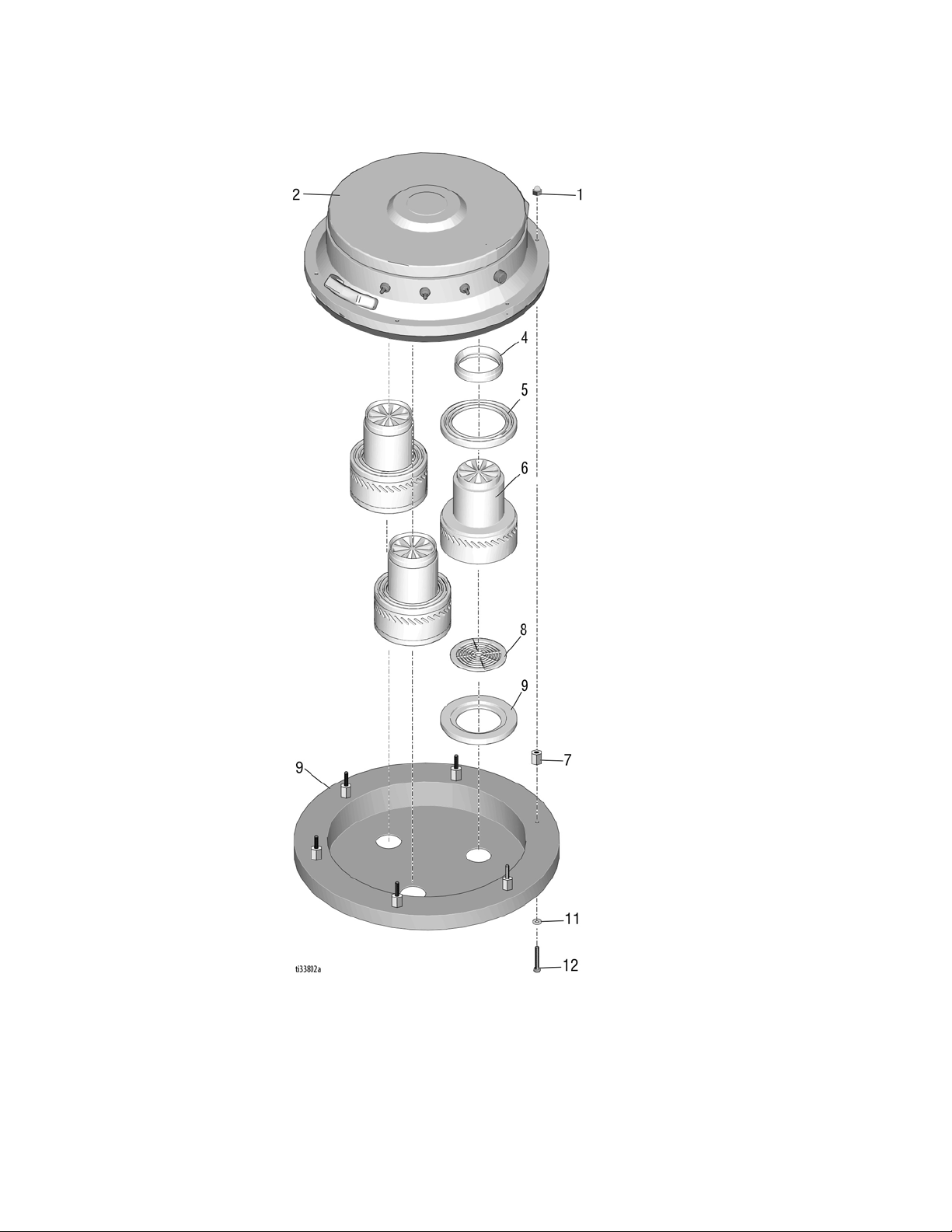
Main MaxiVac Assembly Parts
(MaxiVac)
Ref Part Number Description Qty
1 See page 13-15 Motor Housing Assembly 1
2 See page 17 Auto Filter Cleaner Assembly 1
3 MV.1.891A Filter 1
4 MV.30 Filter Seal Ring 2
5 17X187 Main Frame 1
6 17X188 Dust Collection Tank 1
9* MV.HS Long Vacuum Hose, Standard, 2” (includes item 19) 1
10 MV.26 Vacuum Extension 2
11 MV.24 Vacuum Large Brush 1
12 MV.22 Vacuum Small Brush 1
13 MV.25 Vacuum Floor Nozzle 1
14 MV.27 Vacuum Elbow 1
15‡
(not shown)
17X522 Warning Label (English, French, Spanish) 1
17X523 Warning Label (English, Chinese, Korean) 1
17X524 Warning Label (Icons) 1
16 MV.1.025 Dust Bag Holder 1
17 MV.3.20 Dust Bag (set of 20) 1
18 MV.Y Y-Connector (MV-360 only) 1
19 MV.23 2” Hose Connector 2
‡ Replacement warning, safety labels, tags, and cards are available at no cost.
*2” Heavy-Duty High-Temperature Hose Available: P/N MV.HS.SD

Parts
TBD 13
Motor Housing Assembly
Diagram (MV-360)

Parts
14 TBD
Motor Housing Assembly Parts
List (MV-360)
Part Number Description Qty
1 AHN.25-20 Acorn Nut 6
2 CH-PART(L)-04-a Motor Housing Cover (includes IEC power cord) 1
3 HN.25-20x1.0 Hex Spacer, Long (not shown, located inside item 2)6
4 MV.1.07 Set of Motor Rubber Rings and Plastic Net 3
6 MV.1.06A Motor, 230V 2
7 HN.25-20x.50 Hex Spacer, Short 6
10 MV.1.010 Motor Table 1
11 FLW.M6 Flat Washer 6
12 HX-CS.25-20x2FT Hex Head Screw Cap 6
20 17Y218 Power Cord, IEC 1
21†17X179 Cord Adapter, US, NEMA 1
22†17A242 Cord Adapter, Australia 1
23†15G961 Cord Adapter, Switzerland 1
24†15G960 Cord Adapter, Denmark 1
25†15G959 Cord Adapter, Italy 1
26†15G958 Cord Adapter, Europe, Schuko 1
27†121249 Cord Retainer for Cord Adapters (not shown) 1
† Cord Adapters sold separately
Parts
TBD 15
Motor Housing Assembly Diagram
(MV-600)

Parts
16 TBD
Motor Housing Assembly Parts List (MV-600)
Part Number Description Qty
1 AHN.25-20 Acorn Nut 6
2 CH-PART(L)-04 Motor Housing Cover (includes IEC power cord) 1
3 HN.25-20x1.0 Hex Spacer, Long (not shown, located inside item 2) 6
4 MV.1.07 Set of Motor Rubber Rings and Plastic Net 3
6 MV.1.06A Motor, 230V 3
7 HN.25-20x.50 Hex Spacer, Short 6
10 MV.1.010 Motor Table 1
11 FLW.M6 Flat Washer 6
12 HX-CS.25-20x2FT Hex Head Screw Cap 6
20 17Y218 Power Cord, IEC 1
21†17Y089 Cord Adapter, US, NEMA 21†
22†17A242 Cord Adapter, Australia 22†
23†15G961 Cord Adapter, Switzerland 23†
24†15G960 Cord Adapter, Denmark 24†
25†15G959 Cord Adapter, Italy 25†
26†15G958 Cord Adapter, Europe, Schuko 26†
27†121249 Cord Retainer for Cord Adapters (not shown) 27†
† Cord Adapters sold separately
Parts
TBD 17
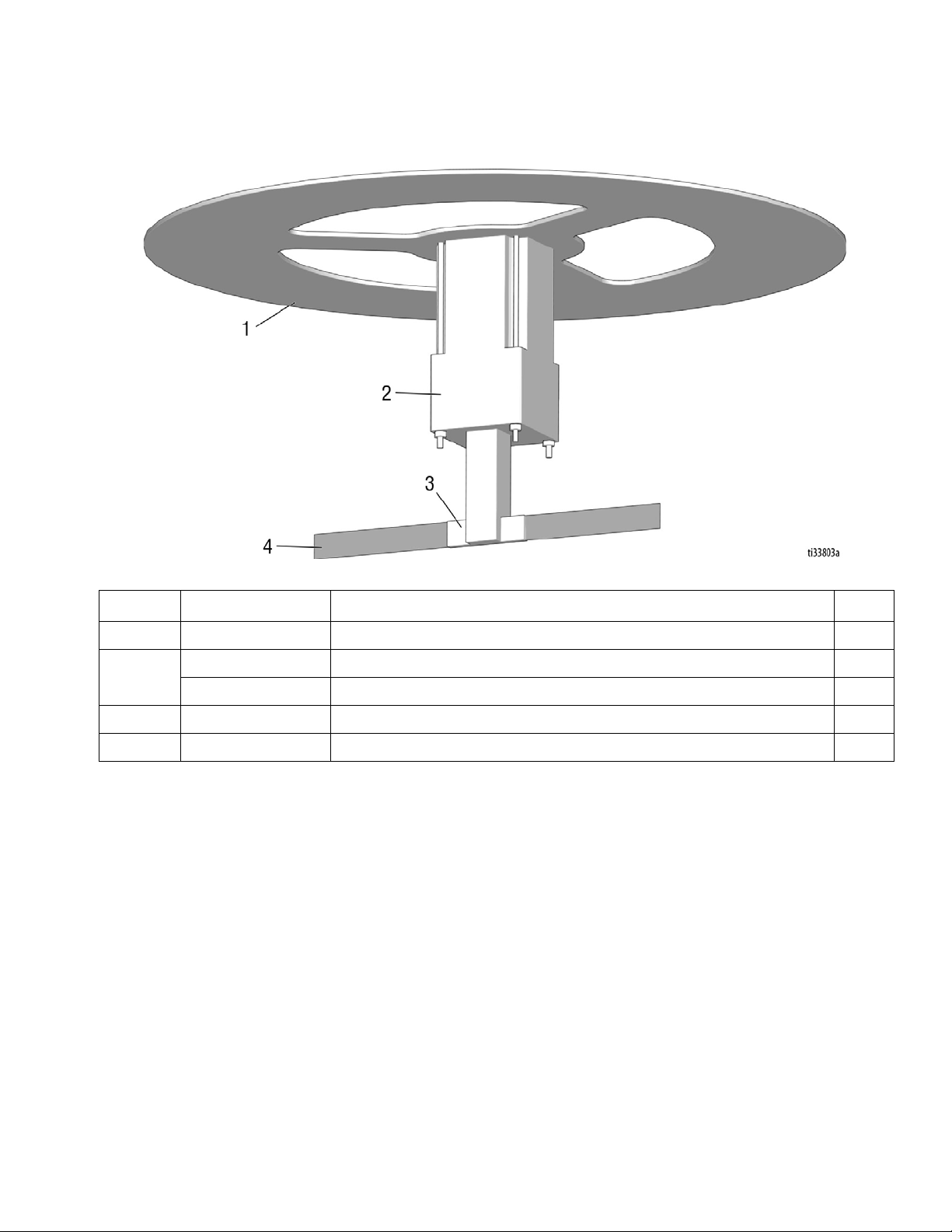
Auto Filter Cleaner Assembly
(MaxiVac)
Part Number Description Qty
1 MV.1.13A Auto Filter Cleaner Assembly Motor Stand 1
2MV.3.12B 120V Filter Cleaner Assembly Motor 1
MV.1.12A 230V Filter Cleaner Assembly Motor 1
3 MV.1.11-C Filter Cleaner Bar, Support (set of 2) 1
4 MV.1.11-D Filter Cleaner Plastic Inserts 2

Parts
18 TBD
MV-SA Assembly and
Accessories

Parts
TBD 19
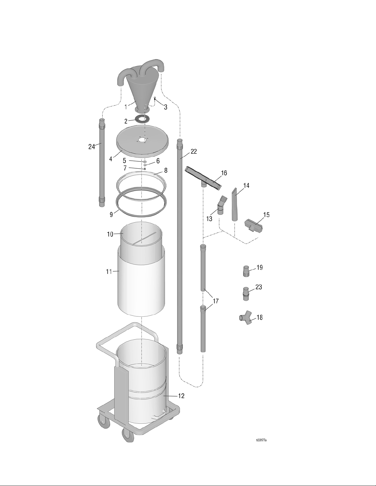
MV-SA Assembly and
Accessories Parts List
Part Number Description Qty
10 MV.HS.SD Long Vacuum Hose 1
11 MV.HS.5 Short Vacuum Hose 1
12 17X694 Debris Tank 1
13 MV.3.20 Dust Bag 1
14 MV.1.025 Dust Bag Holder 1
15 MV.30 Cyclone Seal Ring 1
16 MV.31 Cyclone Ring 1
17 MV.SB.4 Cyclone Head 1
18 17X190 Vacuum Extension 2
19 17X191 Vacuum Elbow 1
20 17X192 Vacuum Floor Nozzle 1
21 17X193 Vacuum Small Brush 1
22 17X194 Vacuum Large Brush 1
23 17X700 Y-Connector 1
24 17X701 2” (50 mm) Connector 2
25 VM.24 2” (50 mm) Hose Coupler 1
Parts
20 TBD
MV-SB Assembly and
Accessories
This manual suits for next models
3
Table of contents


