Sndei S1000.6D User manual

+
-+
-
+
-
+-
+
-
+
-+
-
+
-+
-
+
-
+
-+
-
+
-
+
-+
-
+
-
OPERATING INSTRUCTIONS
Super Mini Class-D Series Car Power Amplifier
Model :
S1000.6D S2000.6D S1000.6D-DTS S2000.6D-DTS S1000.6D-2CH S2000.6D-2CH S2000.2D
U1000.1D U1000.4D
,, ,,,,
,
Before operating the units, please read this manual thoroughly
and retain it for future reference.
+- +- +-
+
-
+
-+
-
+
-+
-
+
-
+- +- +-
+-+-+-+-+-+-
+-+-+-+-+-+-
+- +- +-
+
-
+
-+
-
+
-+
-
+
-
+
- +- +-
+
-
+
-+
-
+
-+
-
+
-
+-
+-+-+-+-+-+-
+-
+
-
+
-+
-
+
-
+-
+-+-+-+-
+-
+-

Thank you for purchasing our Sndei car Audio Amplifiers. Please read this User's Manual before using the unit and save for
future reference.
INTRODUCTION
Our Super Mini Series products have been designed to bring you the highest level of performance and quality, with the
unique features to let you pursue the ultimate listening experience.
All of the amplifiers have variable crossovers built in, with added touches such as subsonic filter, bass equalization and a
bass remote control module option that allows bass control from with in reach of the drivers seat.
To afford you years of listening pleasure, all our amplifiers have a built in diagnostic mode that will detect shorted speaker
leads, low impedance, dangerous high temperatures, DC shorts and will shut down the amp to help prevent serious damage.
In order to get better efficiencyˈThe Super Mini Series products all used Class-D digital mode, efficiency is over 90%.
especially adopting the " Start-stop system" ,( the amplifier can be startup or shut down automatically by detect whether there
is sound signal in. when signal is in the amplifier will start work immediately; when no signal the amplifier will turn to standby
mode in 20 seconds. Applicable model: U1000.4D/S1000.6D/S2000.6D only)
To achieve optimum performance, it is highly recommended that you read this User's Manual before beginning installation.
WARNING
High powered audio systems in a vehicle are capable of generating “Live Concert” high levels of sound pressure. Continued
exposure to excessively high volume sound levels may cause hearing loss or damage. Also, operation of a motor vehicle
while listening to audio equipment at high volume levels may impair your ability to hear external sounds such as: horns,
warning signals, or emergency vehicles, thus constituting to a potential traffic hazard. In the interest of safety, Consumer
Electronics recommends listening at lower volume levels while driving.
PLANNING YOUR SYSTEM
The success of any car stereo system relies on several factors, such as the system design, execution of the installation, and
system setup. Please remember that any system is only as good as its weakest link.
Please remember that higher power systems are not necessarily useful purely for high sound pressure levels, but also to
establish a headroom capability, to reproduce musical peaks cleanly without distortion. Lower power amplifiers will clip earlier
than their more powerful cousins, and cause loudspeaker failure when overdriven, due to the harmonics generated by a
clipped signal, thus overheating voice coils.
Before beginning the installation, consider the following:
a) If you plan to expand your system by adding other components sometime in the future, ensure adequate space is left,
and cooling requirements are met.
b) Should you use high or low level inputs?
Your Amplifier has been designed to accept either High-Level (speaker outputs from your radio) or Low-Level (Pre-Amp
outputs from your radio) signal source.
If you radio / source is equipped with Pre-Amp outputs, it is possible to utilize them to drive the Amplifier and connecting
(Amplifier) to the 2 rear speakers.
Then, use the built-in power of your radio to drive the 2 front speakers.
NOTE : DISTORTION LEVEL IS CONSIDERABLY LOWER FROM PRE-AMP(LOW LEVEL) OUTPUTS, THAN SPEAKER (HIGH LENEL) OUTPUTS.

c) Are your components matched? The peak power rating of your speakers must be equal or greater than the Amplifier’s.
They also must be 2-8 Ohms impedance (This information is normally printed on the speaker magnet).
d) Consider both the length of your leads, and routing when determining the mounting location. Pre-Amp lnput Jacks require
a length of high quality shielded male to male RCA patch cord.
MOUNTING YOUR AMPLIFIER
Amplifiers should be mounted with the fins running horizontally for best convection cooling, to minimize overheating.
Purchase the best quality RCAcables you can afford, for reliability and less engine noise interference in the audio
system.
WOOD
It is highly recommended that the amplifier be mounted to a
board of MDF or other solid structure using the 4 mounting
screws provided. Avoid mounting the
amplifier to metal as this can introduce noise and other
unwanted issues. When mounting the amplifier, ensure that it is
mounted HORIZONTALLY, as shown in the diagram above, for
optimal heat dissipation. Mounting amplifiers to speaker
enclosures is not recommended as this can cause damage to
the amplifier components. When choosing a location for
mounting the amplifier, ensure that you check for clearance
from wires, gas tank, electrical devices and brake lines etc.
The mounting position of your Amplifier will have a great effect on its ability to dissipate the heat generated during normal
operation. It has an ample heat sink for heat dissipation, and also designed with a thermal shut-down (for heat protection)
circuit, making it reasonably tolerant of mounting variations. Any configuration which allows moving air to be directed over the
cooling fins will improve heat dissipation dramatically. DO NOT enclose the amplifier in a small box or cover it so that air
cannot flow around fins.
Temperatures in car trunks have been measured as high as 1400F (600C) in the summer time. Since the thermal shut-down
point for the Amplifier is 1580F (700C), it is easy to see that it must be mounted for maximum cooling capability. To achieve
maximum advantage of convection air flow in an enclosed trunk, mount the amplifier in a vertical position, on a vertical
surface.
Cooling requirements are considerably relaxed when mounting inside the passenger compartment since the driver will not
often allow temperatures to reach a critical point. Floor mounting under the seat is usually satisfactory as long as long as
there is at least 1 inch (2cm) above theAmplifier’s fins for ventilation.
a) Select a suitable location that is convenient for mounting, is accessible for wiring, and has ample room for air circulation
and cooling.
b) Use the amplifier as a temple to mark the mounting holes. Remove the Amplifier and drill 4 holes. USE EXTREME
CAUTION, INSPECT UNDERNEATH SURFACE BEFORE DRILLING.
c) Secure the Amplifier using the screws provided.

WIRING CONNECTIONS
A) CONNECTING THE POWER (FIG.1)
CAUTION:
AS A PRECAUTION, IT IS ADVISABLE TO DISCONNECT THE VEHICLE’S BATTERY BEFORE MAKING CONNECTION
TO THE +12 VOLT SUPPLY WIRING.
4/8 GAUGE (Ticker if planning for additional Amplifiers) wire is recommended for both the power and ground wires. 12 Gauge,
for the remote turn-on wire. Both types are available at most Mobile Audio Dealers or installation Shops.
(1) GROUND : To Vehicle Chassis
Ground each amplifier with as short a ground lead as possible directly to the vehicle chassis using 6 gauge wire or
equivalent to the size of the amplifiers’ power wire. Use a ground distribution block, if you wish, but it is extremely
important to keep the main ground lead from this distribution block to the chassis as short as possible , not more than 12“.
The ground connection integrity to the chassis is very important, and the best way to achieve a good, solid electrical and
mechanical contact is to use a large round crimp lug, crimped and soldered to the ground cable. The next step is to
scrape the paint off the vehicle chassis , slightly larger than the ground
lug, at the connection point. Drill a clearance hole in the chassis, the same size as the lug hole, and use a bolt, spring
washer and nut to securely fasten the ground lug. Use petroleum jelly to coat the bolt/lug connection, to prevent
oxidization with time.
To avoid unwanted ignition noise caused by ground loops, it is essential that the Amplifier be grounded to a clean, bare,
metal surface of the vehicle’s chassis.
NOTE : GROUND WIRE SHOULD NOT BE EXTENDED MORE THAN 3 FT. (1 METER).
(2) +12 Volt (Fused) Constant Power : To Battery (+)
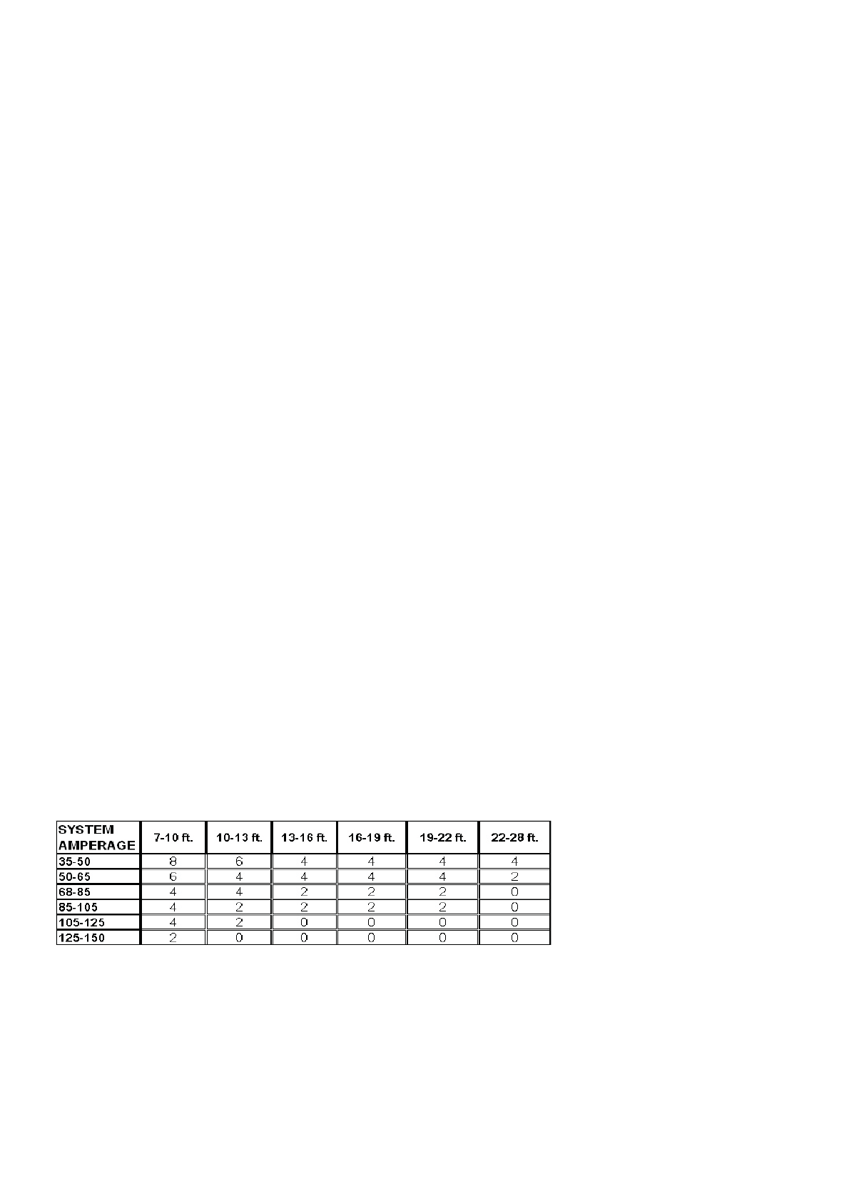
Power and ground connections(see the features matrix on page 11 for proper gauge cables per amplifier):
Use a sufficient gauge power cable and ground cable using the chart below as reference to what size wire you require.
Super Mini series amplifiers require 6 gauge power wire. In a multi amplifier system, add the total value of the
manufacture recommended fusing to get your total system amperage. Some applications may require multiple runs of
power wire to meet the system requirements. In multi amplifier systems it is advisable to mount a large enough fuse right
at the battery, and run one or multiple +12 volt power cables to a fused distribution block near the amplifiers. It is then a
simple matter to connect the +12 volt terminal of each amplifier
to the distribution block. During this process, please ensure that the main power fuse is removed to avoid shorting the
electrical system. The main fuse must be within
12” of the vehicles battery.
Due to the power requirements of the Amplifier, this connection should be made directly to the positive (+) terminal of
battery. For safety measures, install an inline Fuse holder (not included) as close to the battery positive (+) terminal as
possible with an ampere rating; not to exceed total value of fuses in Amp.
S1000.6D ,S1000.6D-2CH,S1000.6D-DTS, S2000.6D-DTS,U1000.4D,U1000.1D: 40A x 2
S2000.6D ,S2000.6D-2CH,S2000.2D: 60A x 2
(3) Remote Turn-On Input : To Power Antenna output of car Stereo
This Amplifier is turned “ON” remotely when the vehicle’s stereo is turned “ON”
NOTE : IF YOUR RADIO DOES NOT HAVE A +12 VOLT OUTPUT LEAD WHEN THE RADIO IS TURNED ON, THE “RMT” TERMINAL
ON THE AMPLIFIER CAN BE CONNECTED TO VEHICLE’S ACCESSORY CIRCUIT THAT IS LIVE WHEN THE KEY IS “ON”.
(4) RCA cables
Run the wiring so that RCA cables are at least 18“ away from power and speaker cables. Keep RCA cables away from
electrical devices in the vehicle that can cause electrical noise, such as electric fuel pumps, emission control modules
and other on-board electronic modules.
(5) Safe connection sequence:
After all cables are run, connect speaker wires to the speakers and amplifiers, then run and plug in RCA cables. Next,
connect all power, ground, and remote turn on leads. Now connect all +12 volt cables to the amplifier/s and distribution
blocks and fuse holders. Finally, connect the main +12 volt cable to the battery, with the main fuse removed, and we are
almost ready to power up the system.
(6) Power up the system:
The following procedure may seem like overkill, but there is nothing more frustrating when turning on a system for the
first time, and it does not work properly immediately.
First, make sure the head unit is off, and turn all level controls to minimum (counterclockwise), including the head unit
volume control. Set all equalizers to 0 dB (no boost), and all crossover frequency controls at approximate frequencies, as
recommended by the loudspeaker manufacturer. Set all input selector and crossover switches as required for the
application. Remove all amplifier fuses, and insert the main fuse at the battery. If the fuse does not blow, you can insert
the fuse in one of the amplifiers, and we are ready to turn on the system. Turn the head unit on, insert a CD, or select a
radio station, and increase the head unit volume control. If the system sounds fine, turn off the head unit, and install fuses
in the remaining amplifiers, one by one, till the complete system is powered up and functioning properly.
TIP: Use the same approach when installing head units, equalizers or any audio equipment for that matter - run short
individual grounds from each piece directly to the vehicle chassis, to minimize ground loops and system noise. All power,
ground and speaker connections should be crimped and soldered for reliability. Make sure that none of the cable
insulation can chafe against exposed metal in the vehicle, causing short circuits to the chassis.
NOTE: This Matrix is a general rule
of thumb. Please refer to the
manufacturers specific requirements.
Super Mini specifications can be
found on pag
All specifications subject to change without prior notice.

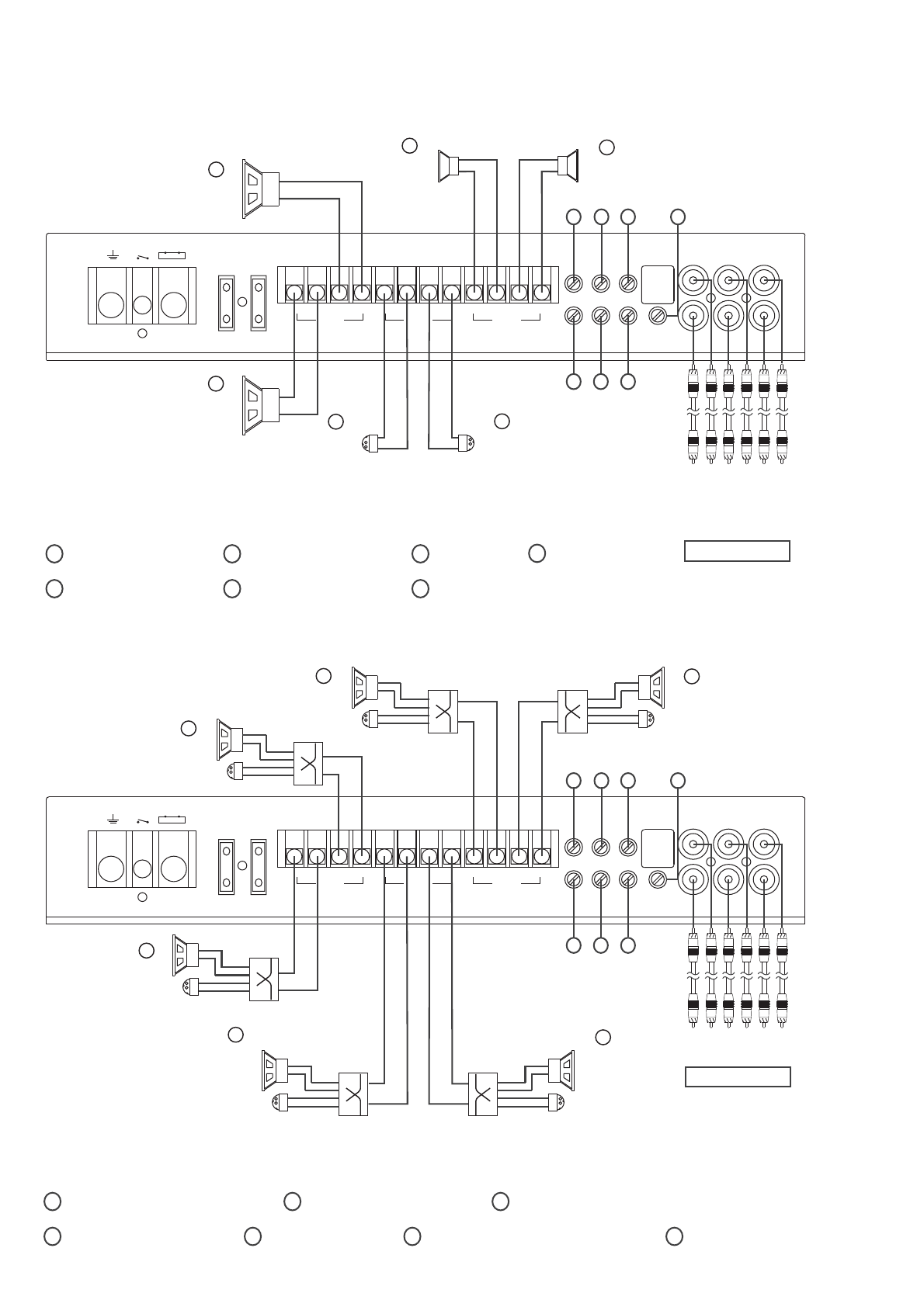
S1000.6D/S2000.6D WIRING CONNECTIONS
+
-+
-
+
-
+-
+
-
+
-+
-
+
-+
-
+
-
+
-+
-
+
-
+
-+
-
+
-
+-+-+-
+
-
+
-+
-
+
-+
-
+
-
+- +- +-
+
-
+
-+
-
+
-+
-
+
-
+
-
+
-+
-
+
-+
-
+
-
POWER
INPUT
FUSES
SPEAKER OUTPUT
SUR FRONT
INPUT
20 2.5KHz
REMOTE
MONO
+-
MONO
+-
MONO
+-
+
-
+
-
SW CEN
+
-
+
-
SR SL
+
-
+
-
FR FL
35 250Hz
SW
20 2.5KHz
MIN MAX MIN MAX MIN MAX MIN MAX
CEN SL FL CEN
SR FR SW
GND REM +BATT 12V
40
40
CENTER
2 8 ohm-
2 8 ohm
-
SUBWOOFER
-2 8 ohm
FRONT L
+
-
-2 8 ohm
SURROUND L
SL
SR
FL
FR
CEN
WS
Radio Output
Bass Boost
Power
0dB 18dB
SUB
Level
7
5
3
1
4
26
Speaker crossover
+
-
+
-
+
-
+
-
+
-
+
-
+
-
+
-
+
-
2 8 ohm
-
SURROUND R
2 8 ohm
-
FRONT R
SURROUND high pass filter
1
2SURROUND level
3FRONT high pass filter
4FRONT level
5low pass filterSUBWOOFER
6SUBWOOFER level 7levelCENTER
1) 5.1 channels The internal mode switch to 5.1CH position(.)
2) 4.1 ( )channel The internal mode switch to 4.1CH position.
POWER
INPUT
FUSES
SPEAKER OUTPUT
SUR FRONT
INPUT
20 2.5KHz
REMOTE
MONO
+
-
MONO
+
-
MONO
+
-
+
-
+
-
SW CEN
+
-
+
-
SR SL
+
-
+
-
FR FL
35 250Hz
SW
20 2.5KHz
MIN MAX MIN MAX MIN MAX MIN MAX
CEN SL FL CEN
SR FR SW
GND REM +BATT 12V
40
40
2 8 ohm
-
SUBWOOFER
-2 8 ohm
FRONT L
-2 8 ohm
SURROUND L
SL
SR
FL
FR
WS
Radio Output
Bass Boost
Power
0dB 18dB
SUB
Level
7
5
3
1
4
26
+
-
+
-
+
-
+
-
+
-
+
-
+
-
+
-
+
-
2 8 ohm
-
SURROUND R
2 8 ohm
-
FRONT R
SURROUND high pass filter
1
2SURROUND level
3FRONT high pass filter
4FRONT level
5low pass filterSUBWOOFER
6SUBWOOFER level 7N/A
+-
+-+-+-+-+-+-
Fuse
Battery
+-
Remote Turn-ON is
connected to Radio's
power antenna lead
or a switchable +12V
Near Battery
Chassis Ground
+-
+
-
+
-+
-
+
-
+-
+
-
+
-+
-
+
-
+-
+-
+
-+
-
+
-
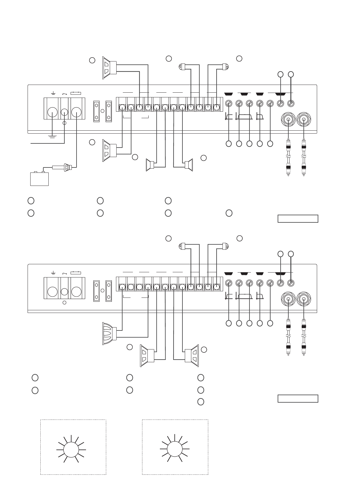
S1000.6D/S2000.6D WIRING CONNECTIONS
+-
+-+-+-+-+-+-
+
-+
-
+
-
+
-+
-
+
-
3)
6 channels The internal mode switch to 6CH position
3
.
,- ( )way speaker output
4)
6 channels 6 The internal mode switch to 6CH position
,- ( )way speaker
.
MID left
MID right
HIGH left
HIGH right
LOW left
LOW right
LOW R
2 8 ohm
-
-2 8 ohm
HIGH L
+
-
HIGH R
2 8 ohm
-
POWER
INPUT
FUSES
SPEAKER OUTPUT
SUR FRONT
INPUT
20 2.5KHz
REMOTE
MONO
+
-
MONO
+
-
MONO
+
-
+
-
+
-
SW CEN
+
-
+
-
SR SL
+
-
+
-
FR FL
35 250Hz
SW
20 2.5KHz
MIN MAX MIN MAX MIN MAX MIN MAX
CEN SL FL CEN
SR FR SW
GND REM +BATT 12V
40
40
LOW L
2 8 ohm
-
+
-
MID R
2 8 ohm
-
-2 8 ohm
MID L
+
-
+
-
+
-
+
-
HIGH high pass filter
1
2
HIGH level
3
MID high pass filter
4
MID level
5
N/A
6
rightLOW level
7
OW leftL level
7
5
3
1
4
26
POWER
INPUT
FUSES
SPEAKER OUTPUT
SUR FRONT
INPUT
20 2.5KHz
REMOTE
MONO
+-
MONO
+-
MONO
+-
+
-
+
-
SW CEN
+
-
+
-
SR SL
+
-
+
-
FR FL
35 250Hz
SW
20 2.5KHz
MIN MAX MIN MAX MIN MAX MIN MAX
CEN SL FL CEN
SR FR SW
GND REM +BATT 12V
40
40
SL
SR
FL
FR
SB L-
-BRS
+
-
+
-
+
-
+
-
+
-
+
-
+
-
+
-
+
-
+
-
+
-
+
-
7
5
3
1
4
26
:Remark In 6CH mode, positive and negative mark on SW channel of
power amplifier is opposite.
+
-
+
-+
-
+
-+
-
+
-
+- +- +-
+
-
+
-+
-
+
-+
-
+
-
+
- +- +-
+
-
+
-+
-
+
-+
-
+
-
Radio Output
Radio Output
2 8 ohm
-
FRONT R
-2 8 ohm
FRONT L
-2 8 ohm
SURROUND L
2 8 ohm
-
SURROUND R
SURROUND high pass filter
1
2SURROUND level
3FRONT high pass filter
4FRONT level
5low pass filterN/A
6SURROUND BACK right level 7SURROUND BACK left level
+-
+
-
+
-+
-
+
-+
-
+
-
2 8 ohm
-
SURROUND
BACK R
2 8 ohm
-
SURROUND
BACK L
:Remark In 6CH mode, positive and negative mark on SW channel of power amplifier is opposite.
+-
+-+-+-+-
+-
+-+-+-+-
+
-
+-

+
-+
-
+
-
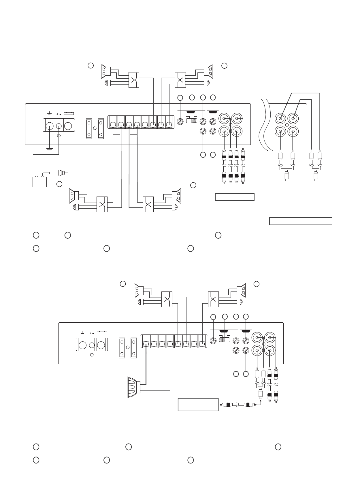
5) Input connection of power amplifier
when radio/CD has 2 way audio channels
(Stereo audio).
6) Input connection of power amplifier when
radio/CD has 4 way audio channels.
+-
+-+-+-+-+-+-
S1000.6D/S2000.6D Specifications
+
-+
-
+
-
+
-+
-
+
-
+- +- +-
+
-
+
-+
-
+
-+
-
+
-
+- +- +-
+
-
+
-+
-
+
-+
-
+
-
..
,,,
1000W : 0 2V 2000W : 0 3V
0.01%
>95dB
0K ohms
SR SL FR FL : 20Hz -2.5KHz SW : 35Hz - 250Hz
1000W : 40A x 2 2000W : 60A x 2
300 x 217 x 50mm
3 Kg
THD (1KHz)
1
ADJUSTABLE SENSITIVITY RANGE
S/N RATIO (A-WEIGHT)
INPUT IMPEDANCE
HPF
FUSE
DIMENSION (L x W x H)
NET WEIGHT
IMPEDANCE CEN, SWSR,SL,FR,FL
65W x 2 / 240W x 1 ()Mono65W x 4 / 240W x2 ()Mono
120W x 2 / 400W x 1 ()Mono120W x 4 / 400W x2 ()Mono
200W x 2 / 700W x 1 ()Mono
200W x 4
8 ohm
4 ohm
2 ohm
S1000.6D OUTPUT
IMPEDANCE CEN, SWSR,SL,FR,FL
100W x 2 400W x 1 ono()M/100W x 4 400W x2 ono()M/
200W x 2 720W x 1 ono()M/200W x 4
400W x 2/
8 ohm
4 ohm
2 ohm
S2000.6D OUTPUT
+
-
+
-+
-
+
-+
-
+
-
+- +- +-
+
-
+
-+
-
+
-+
-
+
-
+
- +- +-
+
-
+
-+
-
+
-+
-
+
-
Left
channel
Y-ADAPTOR
RCA Cable
Right
channel
SUR FRONT
INPUT
20 2.5KHz
REMOTE
35 250Hz
SW
20 2.5KHz
MIN MAX MIN MAX MIN MAX MIN MAX
CEN SL FL CEN
SR FR SW
Radio Output
FR
SL
SR
FL
SUR FRONT
INPUT
20 2.5KHz
REMOTE
35 250Hz
SW
20 2.5KHz
MIN MAX MIN MAX MIN MAX MIN MAX
CEN SL FL CEN
SR FR SW
Radio Output
+-
+-+-+-+-+-+-
+-
+
-
+
-+
-
+
-
+-
+-+-+-+-
+-
+-

+
-+
-
+
-
+-
+-+-+-+-+-+-
+
-+
-
+
-
+
-+
-
+
-
+-+-+-
+
-
+
-+
-
+
-+
-
+
-
+- +- +-
+
-
+
-+
-
+
-+
-
+
-
S1000.6D-DTS/S2000.6D-DTS WIRING CONNECTIONS
AUX
Left channel Input
3
21
POWER
INPUT
FUSES
SPEAKER OUTPUT
SUR FRONT
LINE INPUT
20 2.5KHz
REMOTE
SW
20 2.5KHz
AUX R SW OUT
OPTICAL
3 2505Hz
AUX L COAXIAL
GND REM +BATT 12V
+
-
+
-
SW CEN
+
-
+
-
SR SL
+
-
+
-
FR FL
40
40
AUX Right channel Input
Coaxial Input
SW Output
Optical fiber Input
S1000.6D-DTS/S2000.6D-DTS Specifications
,,,
0.01%
>95dB
SR SL FR FL : 20Hz - 2.5KHz SW : 35Hz - 250Hz
40A x 2
300 x 217 x 50mm
3 Kg
THD (1KHz)
S/N RATIO (A-WEIGHT)
HPF
FUSE
DIMENSION (L x W x H)
NET WEIGHT
IMPEDANCE SWSR,SL,FR,FL,CEN
65W65W x 5
120W120W x 5
200W200W x 5
8 ohm
4 ohm
2 ohm
S1000.6D-DTS OUTPUT
+- +- +-
+
-
+
-+
-
+
-+
-
+
-
+
- +- +-
+
-
+
-+
-
+
-+
-
+
-
Radio Output
SURROUND high pass filter
1 3 FRONT high pass filter 5low pass filterSUBWOOFER
CENTER
2 8 ohm-
-2 8 ohm
FRONT L
+
-
-2 8 ohm
SURROUND L
Speaker crossover
+
-
+
-
+
-
+
-
+
-
+
-
+
-
+
-
2 8 ohm
-
SUBWOOFER
+
-
2 8 ohm
-
SURROUND R
2 8 ohm
-
FRONT R
Remote
control
+-
+
-
+
-+
-
+
-+
-
+
-
Fuse
Battery
+-
Remote Turn-ON is
connected to Radio's
power antenna lead
or a switchable +12V
Near Battery
Chassis Ground
+-
+-+-+-+-
+-
+-+-+-+-
+
-
+-
IMPEDANCE SWSR,SL,FR,FL,CEN
100W100W x 5
200W200W x 5
400W/
8 ohm
4 ohm
2 ohm
S2000.6D-DTS OUTPUT
1) 3 way Electronic Crossover Mode-
2) 2 way Electronic Crossover Mode-
S1000.6D-2CH/S2000.6D-2CH WIRING CONNECTIONS
+
-+
-
+
-
HIGH high pass filter
1 2 MID high pass filter 3MID low pass filter
4LOW low pass filter 5HIGH level 6MID level 7LOW level
POWER
INPUT
FUSES
SPEAKER OUTPUT
HPF HPF
26KHz
MONO
+
-
+
-
+
-
RL
+
-
+
-
RL
+
-
+
-
RL
2 6KHz
LPF
50 2KHz
GND REM +BATT 12V
LINE INPUT
LR
LOW MID HIGH MID LEVEL
50 2KHz
LPF HIGH MID LOW
MIN MAX MIN MAX MIN MAX
LOWHIGH
40
40
Right channel
Left channel
+
-
+
-
+
-
+
-
+
-
+
-
12 3 4 5
6 7
50Hz
52
56
60
80 120 180
300
800
1.5K
2KHz
50Hz – 2KHz Scale
2KHz
2.3K
2.5K
2.7K
2.9K 3.5K 4.2K
4.8K
5.5K
5.7K
6KHz
2KHz – 6KHz Scale
+
-+
-
+
-
+
-+
-
+
-
+- +- +-
+
-
+
-+
-
+
-+
-
+
-
+- +- +-
+
-
+
-+
-
+
-+
-
+
-
+
-
+
-+
-
+
-+
-
+
-
+- +- +-
+
-
+
-+
-
+
-+
-
+
-
+-+-+-
+
-
+
-+
-
+
-+
-
+
-
LOW L
2 8 ohm
-
LOW R
2 8 ohm
-
MID R
2 8 ohm
-
-2 8 ohm
MID L
HIGH R
2 8 ohm
-
-2 8 ohm
HIGH L
Radio Output
POWER
INPUT
FUSES
SPEAKER OUTPUT
HPF HPF
26KHz
MONO
+-
+
-
+
-
RL
+
-
+
-
RL
+
-
+
-
RL
2 6KHz
LPF
50 2KHz
GND REM +BATT 12V
LINE INPUT
LR
LOW MID HIGH MID LEVEL
50 2KHz
LPF HIGH MID LOW
MIN MAX MIN MAX MIN MAX
LOWHIGH
40
40
+
-
+
-
12 3 4 5
6 7
+
-
+
-
+
-
HIGH high pass filter
1 2 MID high pass filter 3MID low pass filter
4SUBWOOFER low pass filter 5HIGH level 6MID level
7SUBWOOFER level
2 8 ohm
-
SUBWOOFER
LOW L
2 8 ohm
-
LOW R
2 8 ohm
-
HIGH R
2 8 ohm
-
-2 8 ohm
HIGH L
Right channel
Left channel
Radio Output
Fuse
Battery
+-
Remote Turn-ON is
connected to Radio's
power antenna lead
or a switchable +12V
Near Battery
Chassis Ground
+-
+-+-+-+-
+-
+-+-+-+-
+-
+-

+
-+
-
+
-
+-
+
-
+
-+
-
+
-+
-
+
-
S1000.6D-2CH/S2000.6D-2CH Specifications
+
-+
-
+
-
0.01%
>95dB
50Hz - 4KHz, 2KHz - 6KHz
40A x 2
300 x 217 x 50mm
3 Kg
THD (1KHz)
S/N RATIO (A-WEIGHT)
INPUT IMPEDANCE
FUSE
DIMENSION (L x W x H)
NET WEIGHT
IMPEDANCE LOWMID,HIGH
65W x 4
120W x 4
200W x 4
8 ohm
4 ohm
2 ohm
S1000 6D-2CH OUTPUT.
IMPEDANCE
100W x 4
200W x 4
/
8 ohm
4 ohm
2 ohm
S2000 6D-2CH OUTPUT.
LOW
MID,HIGH
65W x 2 / 240W x 1 ()Mono
120W x 2 / 400W x 1 ()Mono
200W x 2 / 700W x 1 (Mono)
100W x 2 400W x 1 ono()M/
200W x 2 720W x 1 ono()M/
400W x 2
+
-+
-
+
-
+- +- +-
+
-
+
-+
-
+
-+
-
+
-
+- +- +-
+
-
+
-+
-
+
-+
-
+
-
+
-
+
-+
-
+
-+
-
+
-
+- +- +-
+
-
+
-+
-
+
-+
-
+
-
+-+-+-
+
-
+
-+
-
+
-+
-
+
-
+-
+
-
+
-+
-
+
-+
-
+
-
+-
+-+-+-+-
+-
+-+-+-+-
+-
+-

POWER
INPUT
FUSES
SPEAKER OUTPUT
MONO
+
-
L
GND
+
-
R
REM +BATT 12V
+
-
PHASE
0
0
180
0
LOW
PASS
35 250Hz
REMOTE BASS
EQ
0 18dB
SUB
SONIC
15 35Hz LPF FULL HPF
HI
PASS
50 4KHz MIN MAX
LEVEL
LINE INPUT
LR
40
40
+
-
S2000.2D WIRING CONNECTIONS
N/A
1 2 N/A 3N/A 4N/A 5N/A 6Level
+-
+
-
+
-+
-
+
-+
-
+
-
1) Full Range Stereo
Bass Boost
Power
0dB 18dB
POWER
INPUT
FUSES
SPEAKER OUTPUT
MONO
+
-
L
GND
+
-
R
REM +BATT 12V
+
-
PHASE
001800
LOW
PASS
35 250Hz
REMOTE BASS
EQ
0 18dB
SUB
SONIC
15 35Hz LPF FULL HPF
HI
PASS
50 4KHz MIN MAX
LEVEL
LINE INPUT
LR
40
40
+
-
+
-
+
-
+
-
1 2 3
4 5 6
2) Mono Bass Speaker
3) Full Range Mono
POWER
INPUT
FUSES
SPEAKER OUTPUT
MONO
+
-
L
GND
+
-
R
REM +BATT 12V
+
-
PHASE
001800
LOW
PASS
35 250Hz
REMOTE BASS
EQ
0 18dB
SUB
SONIC
15 35Hz LPF FULL HPF
HI
PASS
50 4KHz MIN MAX
LEVEL
LINE INPUT
LR
40
40
4 8 ohm
-
Phase
1 2 SUBWOOFER low pass filter
3Bass EQ 4SUB Sonic 5N/A 6Level
N/A
1 2 N/A 3N/A
4N/A 5High pass filter 6Level
+
-
+-+-+-
+
-
+
-+
-
+
-+
-
+
-
+- +- +-
+
-
+
-+
-
+
-+
-
+
-
+
-
+
-+
-
+
-+
-
+
-
+- +- +-
+
-
+
-+
-
+
-+
-
+
-
+
- +- +-
+
-
+
-+
-
+
-+
-
+
-
+-
+
-
+
-+
-
+
-+
-
+
-
-2 8 ohm
SURROUND R
2 8 ohm
-
SURROUND L
Right channel
Left channel
Full Range Stereo Line Input
Full Range Line Input
Via Y-Adapter From Mono Source
Mono
2 8 ohm
-
SUBWOOFER
SUB
Level
Fuse
Battery
+-
Remote Turn-ON is
connected to Radio's
power antenna lead
or a switchable +12V
Near Battery
Chassis Ground
Full Range Line Input
Via Y-Adapter From Mono Source
Mono
+-
+-+-+-+-
+-
+-+-+-+-
+
-
+
-

+
-+
-
+
-
+-
+
-
+
-+
-
+
-+
-
+
-
+
-+
-
+
-
+
-+
-
+
-
0.1V
0.01%
>95dB
0K ohms
60A x 2
300 x 217 x 50mm
3 Kg
THD (1KHz)
1
ADJUSTABLE SENSITIVITY RANGE
S/N RATIO (A-WEIGHT)
INPUT IMPEDANCE
FUSE
DIMENSION (L x W x H)
NET WEIGHT
IMPEDANCE
300W x 2 1100W x1 ono()M/
600W x 2 2000W x1 ono()M/
1000W x 2
8 ohm
4 ohm
2 ohm
OUTPUT
+-+-+-
+
-
+
-+
-
+
-+
-
+
-
+- +- +-
+
-
+
-+
-
+
-+
-
+
-
+
-
+
-+
-
+
-+
-
+
-
+- +- +-
+
-
+
-+
-
+
-+
-
+
-
S2000.2D Specifications
+-+-+-
+
-
+
-+
-
+
-+
-
+
-
+-
+
-
+
-+
-
+
-+
-
+
-
+-
+-+-+-+-
+-
+-+-+-+-
+
-
+
-
+
-+
-
+
-
+-
+
-
+
-+
-
+
-+
-
+
-
+
-+
-
+
-
+
-+
-
+
-
+- +- +-
+
-
+
-+
-
+
-+
-
+
-
+- +- +-
+-+-+-+-+-+-
+-+-+-+-+-+-
+- +- +-
+
-
+
-+
-
+
-+
-
+
-
U1000.4D WIRING CONNECTIONS
1) 4 channels
+- +- +-
+
-
+
-+
-
+
-+
-
+
-
+-
+
-
+
-+
-
+
-+
-
+
-
Fuse
Battery
+-
Remote Turn-ON is
connected to Radio's
power antenna lead
or a switchable +12V
Near Battery
Chassis Ground
SR
SL
FR
FL
5
3
1
6
4
GND REM +BATT 12V
POWER
INPUT
FUSES
SPEAKER OUTPUT
MONO
+
-
+
-
+
-
SR SL
+
-
+
-
FR FL
20 2.5KHz 20 2.5KHz
MIN MAX MIN MAX SR FR
INPUT
SL FL
X-OVER
BP HI
LOW
PASS
35 250Hz
SL/SR FL/FR
HI PASS HI PASS
40
40
NA/
1
5FRONT high pass filter
3SURROUND high pass filter
6FRONT level
4SURROUND level
+
-
+
-
+
-
+
-
+
-
+
-
+
-
+
-
+
-
5
3
1
6
4
2) 2.1 channels
GND REM +BATT 12V
POWER
INPUT
FUSES
SPEAKER OUTPUT
MONO
+-
+
-
+
-
SR SL
+
-
+
-
FR FL
20 2.5KHz 20 2.5KHz
MIN MAX MIN MAX SR FR
INPUT
SL FL
X-OVER
BP HI
LOW
PASS
35 250Hz
SL/SR FL/FR
HI PASS HI PASS
40
40
+
-
+
-
+
-
+
-
2
2The X-OVER switch must be in the HI position
2
+
-
SR FR
INPUT
SL FL
+
-
-2 8 ohm
FRONT L
2 8 ohm
-
FRONT R
-2 8 ohm
SURROUND L
Speaker crossover
2 8 ohm
-
SURROUND R
Radio Output
Right channel
Left channel
Full Range Stereo Line Input
-2 8 ohm
FRONT L
2 8 ohm
-
FRONT R
2 8 ohm
-
SUBWOOFER
SURROUND low pass filter
1
5
FRONT high pass filter
3
SUB Sonic
6
FRONT level
4
SURROUND level
2The X-OVER switch must be in the BP position
Right channel
Left channel
INPUT

+
-+
-
+
-
+-
+
-
+
-+
-
+
-+
-
+
-
+
-+
-
+
-
+
-+
-
+
-
+- +- +-
+
-
+
-+
-
+
-+
-
+
-
+- +- +-
+-+-+-+-+-+-
+-+-+-+-+-+-
+- +- +-
+
-
+
-+
-
+
-+
-
+
-
+
- +- +-
+
-
+
-+
-
+
-+
-
+
-
+-
+
-
+
-+
-
+
-+
-
+
-
U1000.4D Specifications
+-
+
-
+
-+
-
+
-
+-
+
-
+
-+
-
+
-
.
0.2V
0.01%
>95dB
10K ohms
035
40A x 2
248 x 166 x 45mm
2 Kg
THD (1KHz)
STANDBY CURRENT A
ADJUSTABLE SENSITIVITY RANGE
S/N RATIO (A-WEIGHT)
INPUT IMPEDANCE
FUSE
DIMENSION (L x W x H)
NET WEIGHT
IMPEDANCE
65W x 2 / 250W x1 ()Mono
120W x 2 / 400W x1 ()Mono
200W x 2 / 700W x1 ()Mono
8 ohm
4 ohm
2 ohm
OUTPUT
SR,SL FR,FL
65W x 2
120W x 2
200W x 2
+
-
+
-

+
-+
-
+
-
+-
+
-
+
-+
-
+
-+
-
+
-
+
-+
-
+
-
+
-+
-
+
-
+-+-+-
+-+-+-+-+-+-
+- +- +-
+
-
+
-+
-
+
-+
-
+
-
+
-
+
-+
-
+
-+
-
+
-
+- +- +-
+-+-+-+-+-+-
+
- +- +-
+-+-+-+-+-+-
+-
+
-
+
-+
-
+
-+
-
+
-
U1000.1D WIRING CONNECTIONS
+-
+
-
+
-+
-
+
-
+-
+
-
+
-+
-
+
-
LINE INPUT
LR
GND REM +BATT 12V
POWER
INPUT
FUSES
SPEAKER OUTPUT
+
-
REMOTE
PHASE
001800
LOW
PASS
35 250Hz
BASS
EQ
0 18dB
SUB
SONIC
15 35Hz MIN MAX
LEVEL
40
40
4
2
1
11)SUBWOOFER
Phase
13
Bass EQ
2
SUBWOOFER low pass filter
5
Level
4
SUB Sonic
+
-
3 5
INPUT
Bass Boost
Power
0dB 18dB
SUB
Level
LINE INPUT
LR
GND REM +BATT 12V
POWER
INPUT
FUSES
SPEAKER OUTPUT
+
-
REMOTE
PHASE
001800
LOW
PASS
35 250Hz
BASS
EQ
0 18dB
SUB
SONIC
15 35Hz MIN MAX
LEVEL
40
40
4
2
1
22)SUBWOOFER
+
-
3 5
Bass Boost
Power
0dB 18dB
+
-
Fuse
Battery
+-
Remote Turn-ON is
connected to Radio's
power antenna lead
or a switchable +12V
Near Battery
Chassis Ground
2 8 ohm
-
SUBWOOFER
SUB
Level
4 8 ohm
-
SUBWOOFER
4 8 ohm
-
SUBWOOFER
Phase
13
Bass EQ
2
SUBWOOFER low pass filter
5
Level
4
SUB Sonic
INPUT

+
-+
-
+
-
+-
+
-
+
-+
-
+
-+
-
+
-
+
-+
-
+
-
+
-+
-
+
-
+-+-+-
+-+-+-+-+-+-
+-+-+-
+
-
+
-+
-
+
-+
-
+
-
+
-
+
-+
-
+
-+
-
+
-
+- +- +-
+-+-+-+-+-+-
+
- +- +-
+-+-+-+-+-+-
+-
+
-
+
-+
-
+
-+
-
+
-
+-
+
-
+
-+
-
+
-
+-
+
-
+
-+
-
+
-
315W x1
600W x1
1000W x1
IMPEDANCE
8 ohm
4 ohm
2 ohm
OUTPUT
+
-
+
-
U1000.1D Specifications
.
0.2V
0.01%
>95dB
50K ohms
065
40A x 2
248 x 166 x 45mm
2 Kg
THD (1KHz)
STANDBY CURRENT A
ADJUSTABLE SENSITIVITY RANGE
S/N RATIO (A-WEIGHT)
INPUT IMPEDANCE
FUSE
DIMENSION (L x W x H)
NET WEIGHT

+
-+
-
+
-
+-
+
-
+
-+
-
+
-+
-
+
-
+
-+
-
+
-
+
-+
-
+
-
+- +- +-
+
-
+
-+
-
+
-+
-
+
-
+- +- +-
+-+-+-+-+-+-
:
:
:
Sndei Electronic Technology Co., Ltd
1/F., No.91 Kau Pui Lung Road, To Kwa Wan, Kowloon,
Hong Kong
Tel +852 2135 7128
Fax +852 2135 7127
E mark[email protected]
Web
:
mail
www.sndei.com
Your best partner !
Super CLASS-D Series Digital Power Car Amplifier
Leading Technology
First-Class Sound Quality
Supper Power
High Efficiency
Spreading Green Culture
Promoting Low-Carbon Life
! !
+-+-+-+-+-+-
+- +- +-
+-+-+-+-+-+-
+
- +- +-
+
-
+
-+
-
+
-+
-
+
-
+-
+-+-+-+-+-+-
+-
+
-
+
-+
-
+
-
+-
+
-
+
-+
-
+
-
+-
+-
This manual suits for next models
8
Table of contents
Popular Car Amplifier manuals by other brands

Audiosystem
Audiosystem X-80.4 D owner's manual

Diamond Audio Technology
Diamond Audio Technology D7056 installation manual

Diamond Audio Technology
Diamond Audio Technology D7054 installation manual

MB QUART
MB QUART FORMULA FX1.400 installation manual

Audiosystem
Audiosystem R-1250.1 D-24V owner's manual

Sony
Sony XM-D1000P5 Marketing Specifications operating instructions


