Soga Sincro EW-AC Series User manual
MANUALE D’USO E MANUTENZIONE
USE AND MAINTENANCE MANUAL
MANUEL POURL’EMPLOI ET L`ENTRETIEN
BEDIENUNGS - UND WARTUNGANLEITUNG
MANUAL PARA EL USO Y MANTENIMIENTO
serie EW-AC

! !!
INFORMAZIONI GENERALI
La manutenzione della saldatrice, verifica e
sostituzione di parti deve essere effettuata
esclusivamente da personale qualificato.
VERIFICHE PRELIMINARI
Prima dell’utilizzo si raccomanda di esaminare
la saldatrice per verificare che non abbia subito
danni durante il trasporto.
IMMAGAZZINAGGIO
In caso di inutilizzo prolungato, la saldatrice
deve essere immagazzinata in luogo asciutto
e coperto.
Primadellamessainservizio,dopolunghipe rio-
di di inattività, controllare la bontà d’isolamento
ditutti gli avvolgimenti; valori accettabili devono
essere maggiori di 2M•.
In caso contrario si deve procedere all’essicca-
zione della sola saldatrice in forno (60÷70°C).
INSTALLAZIONE
Prima della messa in funzione, verificare
l’esecuzione dei collegamenti, e l’assenza di
impedimenti alla rotazione del rotore.
Fare attenzione che le aperture per l’aspira-
zione e espulsione dell’aria non siano ostruite
o danneggiate, evitare inoltre che la saldatrice
aspiril’ariacaldaespulsadallasaldatrice stessa
e/o dal motore.
COLLEGAMENTO ELETTRICO
Rispettare le norme di sicurezza vigenti del
paese d’utilizzo.
Verificare che i dati di targa siano conformi alle
caratteristiche dell’impianto a cui la macchina
verrà collegata.
Provvedere al collegamento a terra del
gruppo.
MANUTENZIONE
Verificare che non ci siano anomalie, come
vibrazioni - rumori - uscite d’aria ostruite.
SMALTIMENTO
La saldatrice è costituita in massima parte da
acciaio, rame, alluminio.Al termine dell’utilizzo
della macchina rivolgersi ad una agenzia di
smaltimento di materiali ferrosi, ed evitare di
disperdere parti di saldatrice nell’ambiente.
ATTENZIONE!
Non toccare la saldatrice durante il funzio-
namento e subito dopo l’arresto del gruppo,
in quanto vi potrebbero essere superfici a
temperatura elevata
Lemacchineelettriche rotanti sono macchi-
nechepresentanopartipericolose in quanto
poste sotto tensione o dotate di movimento
durante il funzionamento, pertanto:
- un uso improprio
- la rimozione delle protezioni e lo scolle-
gamento dei dispositivi di protezione
- la carenza di ispezioni e manutenzione
possono causare gravi danni a persone
o cose.
FOREWORD
All maintenance and controls on the welder
and any part replacements must be carried out
exclusively by qualified staff.
PRELIMINARY CHECKS
Before using the welder be sure to control it for
transport damage.
STORAGE
Intheeventofprolongeddisuse,theweldermust
be stored in a dry, sheltered location.
Before starting it up after a long shutdown
period, control the efficiency of the insulation
on the windings; values over 2M• can be
considered acceptable.
If this is not the case, the welder alone should
be oven dried at 60-70°C.
INSTALLATION
Before starting up the welder, checkthe
wiring connections and that the rotor can
rotate freely.
Make sure that the air suction and discharge
ventsare not clogged ordamaged, what’s more
ensure that the welder does not intake hot air
discharged by the welder and/or motor.
POWER CONNECTIONS
Respect the country’s statutorysafety
standards.
Make sure that the ID plate data conform with
the electricityplant’s characteristics before
connecting.
Connect the unit to earth.
MAINTENANCE
Checkfo r irregularities, such as vibrations –o d d
noises – clogged air outlets.
DISMANTLING
Large part of the welder is made of steel,
copper and aluminium. When discarding the
machine contact a scrap iron merchant, and
do not dispose of any parts of the welder in
the environment.
CAUTION!
Do not touch the welder while in operation
and immediately after the unit is shutdown,
since there could be hot surfaces
Rotating electrical machinery involve haz-
ardousparts since they are undervoltage or
moving during operation, therefore:
- improper use
- removal of protective guards and discon-
nection of safeties
- lack of inspection and maintenance
can cause severe damage to persons or
objects.
INFORMATIONS GÉNÉRALES
Lamaintenancedelasoudeuse, le contrôle et le
remplacement de pièces doivent être effectués
exclusivement par du personnel qualifié.
CONTRÔLES PRÉLIMINAIRES
Avant l’utilisation, nous recommandons d’exa-
miner la soudeuse pour vérifier qu’elle n’a pas
subi de dommages durant le transport.
STOCKAGE
En cas de non-utilisation prolongée, la sou-
deuse doit être stockée dans un endroit sec
et couvert.
Avant la mise en service, après de longues pé-
riodes d’inactivité, contrôler l’efficacité de l’iso-
lement de tous les enroulements ; les valeurs
acceptables doivent être supérieures à 2 M•.
Encascontraire,ilfautprocéderauséchageuni-
quement de la soudeuse au four (60÷70°C).
INSTALLATION
Avant la mise en marche, vérifier toutes les
connexions et que rien n’empêche la rotation
du rotor.
Veiller à ce que les ouvertures pour l’aspiration
etl’expulsion de l’air ne soient pas bouchées ou
endommagées,éviterenoutrequela soudeuse
aspire l’air chaud expulsé par la soudeuse
proprement dite et/ou par le moteur.
BRANCHEMENT ÉLECTRIQUE
Respecter les normes de sécurité en vigueur
dans le pays d’utilisation.
Vérifier que les données de la plaque sont
conformes aux caractéristiques de l’installation
à laquelle la machine sera branchée.
Effectuer la mise à la terre du groupe.
MAINTENANCE
Vérifier qu’il n’y a pas d’anomalies telles que
vibrations, bruits, sorties d’air bouchées.
MISE AU REBUT
La soudeuse est constituée pour la majeure
partie d’acier, cuivre et aluminium. Quand
la machine n’est plus utilisée ou utilisable,
s’adresser à une agence pour le recyclage des
matériaux ferreux et éviter d’abandonner des
parties de la soudeuse dans la nature.
ATTENTION !
Ne pas toucher la soudeuse durant le fonc-
tionnement et juste après l’arrêt du groupe
car certaines surfaces pourraient être à une
température élevée.
Lesmachinesélectriquesrotativessontdes
machinesquiprésentent des parties dange-
reuses dans la mesure où elles sont sous
tension ou munies de mouvement au cours
du fonctionnement, par conséquent :
- une utilisation impropre
- l’enlèvement des protections et la décon-
nexion des dispositifs de protection
- la négligence dans les contrôles ou dans
la maintenance
peuvent causer de graves dommages aux
personnes ou aux choses.

!!
ALLGEMEINE INFORMATIONEN
Die Wartung der Schweißmaschine sowie die
Überprüfung und das Auswechseln von Te ilen
darf nur von Fachpersonal vorgenommen
werden.
VORUNTERSUCHUNGEN
Vor Benutzung wird dringend empfohlen, die
Schweißmaschine auf eventuelle während des
Transports erlittene Schäden zu untersuchen.
LAGERUNG
Im Fall einer längeren Nichtbenutzung muß
die Schweißmaschine an einem trockenen und
überdachten Ort gelagert werden.
Vor der Inbetriebnahme nach langen Stillstand-
zeitendeneinwandfreienZustandderIsolierung
aller Wicklungen kontrollieren; akzeptable
Werte müssen höher als 2M• sein.
Andernfalls muß eine Trocknung der alleinigen
Schweißmaschine im Ofen vorgenommen
werden (60÷70°C).
INSTALLIERUNG
Vor der Inbetriebnahme die Ausführung der
Anschlüsse überprüfen und sicherstellen, daß
keine Behinderungen an der Rotation des
Rotors vorliegen.
Daraufachten,daßdieAnsaug- undAusstoßöff-
nungen der Luft nicht verstopft oder beschädigt
sind. Außerdem vermeiden, daß die Schweiß-
maschinedievonihr selbst und/oder vom Motor
ausgestoßene warme Luft ansaugt.
ELEKTRISCHER ANSCHLUSS
Die im Benutzungsland geltenden Sicherheits-
normen beachten.
Überprüfen, daß die Daten des Typenschilds
den Eigenschaften der Anlage, an die die Ma-
schine angeschlossen wird, entsprechen.
Den Erdungsanschlußdes Aggregats vor-
nehmen.
WARTUNG
Überprüfen, daß keine Anomalien wie Vibrati-
onen - Geräusche - verstopfte Luftausgänge
vorliegen.
ENTSORGUNG
Die Schweißmaschine besteht hauptsächlich
aus Stahl, Kupfer, Aluminium. Am Ende der
BenutzungderMaschine mußm a n sich aneine
Agentur zur Entsorgung eisenhaltiger Materia-
lienwenden und vermeiden, TeilederSchweiß-
maschine in der Umwelt zu entsorgen.
ACHTUNG!
DieSchweißmaschinewährenddesBetriebs
undsofortnach demA nhaltendesAggregats
nichtberühren,da s i eOberflächenmithoher
Temperatur aufweisen könnte.
Elektrische Rotationsmaschinen sind Ma-
schinen, die gefährliche Teile aufweisen, da
sieunterSpannungstehenund währenddes
Betriebs mit Bewegung ausgestattet sind;
daher können
- ein unsachgemäßer Gebrauch
- das Entfernen der Schutzabdeckungen
unddasAbtrennen der Schutzvorrichtun-
gen
- unzureichende Inspektionen und War-
tung
schwere Personen- oder Sachschäden
verursachen.
INFORMACIONES GENERALES
Tanto el mantenimiento de la soldadora como
la verificación y sustitución de las partes serán
realizadosúnicaye xclusivamente por personal
cualificado.
VERIFICACIONES PRELIMINARES
Antes de utilizar la soldadora recomendamos
controlarla, para asegurarse de que no se haya
estropeado durante el transporte.
ALMACENAJE
En caso de largos periodos de inactividad,
habrá que almacenar la soldadora en un lugar
seco y cubierto.
Tras largos periodos de inactividad de la
soldadora y antes de su puesta en servicio,
hay que controlar las buenas condiciones del
aislamientodetodoslosbobinados.Losvalores
admitidos serán superiores a 2M•.
De no ser así, se dispondrá el secado de la
soldadora en el horno (60÷70°C).
INSTALACIÓN
Examinar el estado de las conexiones antes
de la puesta en función, y que no haya impe-
dimentos al girar el rotor.
Tener cuidado de que no estén obstruidas
o estropeadas las aperturas de aspiración
yexpulsión del aire. Asimismo, evitar que la
soldadora aspire el aire caliente que sale de
ella misma y/o del motor.
CONEXIÓN ELÉCTRICA
Cumplir las vigentes normas de seguridad
locales.
Verificarquelosdatosdela placa correspondan
a las características de la instalación a la que
la máquina será conectada.
Realizar la conexión de tierra del grupo.
MANTENIMIENTO
Verificarquenohayaanomalías,comovibracio-
nes, ruidos o salidas de aire obstruidas.
ELIMINACIÓN
La soldadora está casi toda conformada por
acero, cobre y aluminio. Al terminar la vida
útil de la máquina, acudir a una compañía de
eliminación de materiales ferrosos. Evítese la
liberación de partes de la soldadora al medio
ambiente.
¡ATENCIÓN!
No tocar la soldadora mientras está
funcionando ni tampoco inmediatamente
después de la parada del grupo, pues la
temperatura de algunas de las superficies
podría ser elevada.
Las máquinas eléctricas rotatorias incor-
poran partes peligrosas, ya que durante
su funcionamiento están bajo tensión o se
están moviendo, por tanto:
- el uso impropio
- el desmontaje de las protecciones y
desconexión de los dispositivos de
protección
- inspecciones y mantenimiento carentes
pueden ocasionar graves daños a las per-
sonas y cosas.
REGOLAZIONE DELLA VELOCITA’
La frequenza e la tensione dipendono
direttamente dalla velocità di rotazione, la
quale deve quindi rimanere il più possibile
costante al variare del carico.
Considerando che il sistema di regolazione
della velocità dei motori di trascinamento
presenta in generale una leggera caduta
di giri tra vuoto e carico, si raccomanda di
regolare la velocità a vuoto circa il 3÷4%
superiore alla velocità nominale.
SPEED ADJUSTMENT
Frequency and voltage depend directly on
thespeedofrevolution, whichmust therefore
remain as constant as possible when the
load varies.
The speed adjustment system of the
drive motors usually gives a slight drop in
revolutions between no load and load, so
when the no load speed is being adjusted,
it is best to set it at approx. 3-4% above
the rated speed.
RÉGLAGE DE LA VITESSE
La fréquence et la tension dépendent di-
rectement de la vitesse de rotation qui doit
rester le plus possible constante quand la
charge varie.
Vu que le système de réglage de la vitesse
des moteurs d’entraînement présente en
général une légère baisse du nombre de
tours à vide ou en charge, il est conseillé
de régler la vitesse à vide à une valeur
supérieure de 3 à 4 % par rapport à la
vitesse nominale.
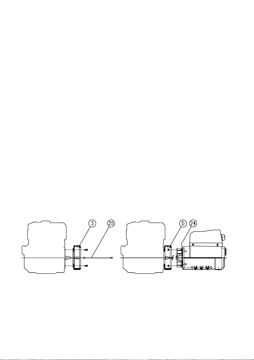
ISTRUZIONI PER IL MONTAGGIO
(FORMA IM B35)
ATTENZIONE: prima del montaggio verifi-
care che le sedi coniche di accoppiamento
(sia della saldatrice che del motore) siano
regolari e ben pul i te.
1) Fissare lo scudo copriventola (3) al
motore (dopo averlo tolto dalla salda-
trice).
2) Applicare il tirante (25) per il fissaggio
assiale del rotore avvitandolo sulla spor-
genza dell’albero motore.
3) Fissare la saldatrice completa (statore
erotoreassieme) allo scudo usandoi4t i ranti
M8 (24) e i dadi autobloccantiM8(D).
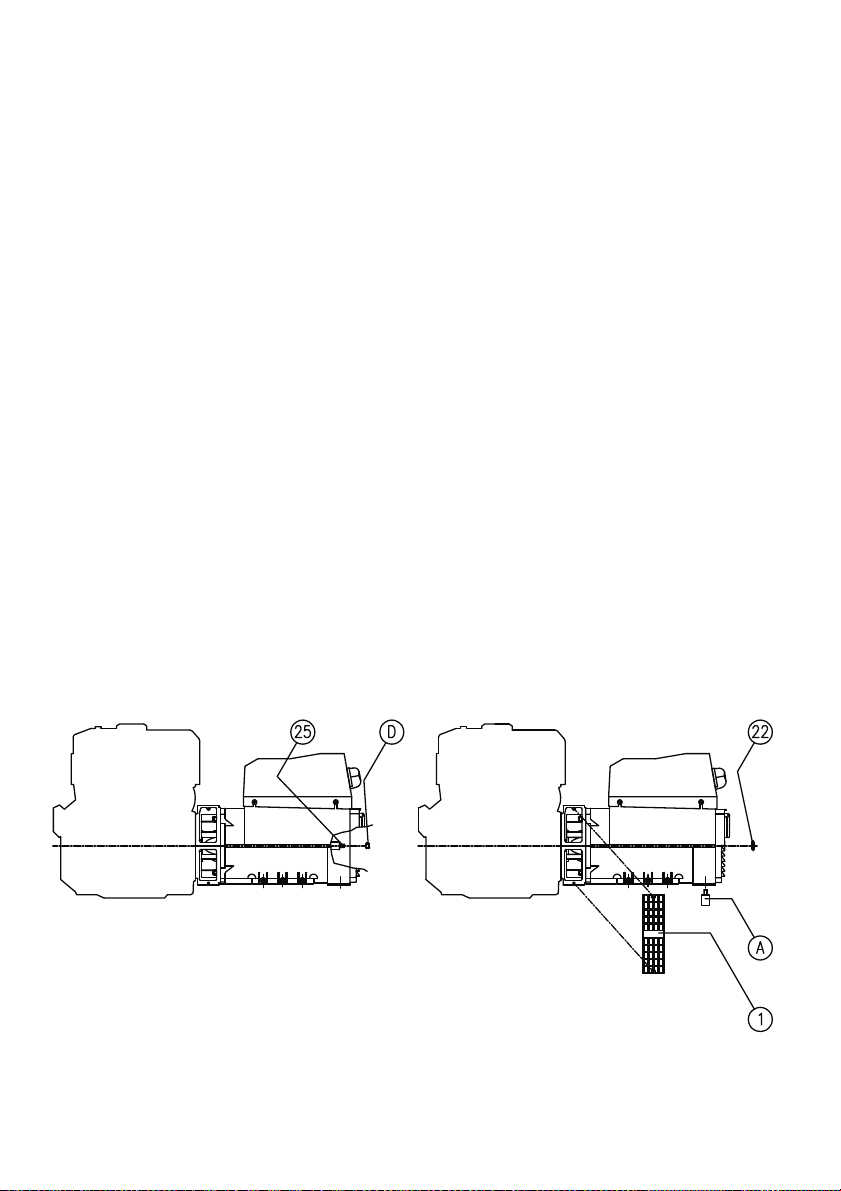
4) Verificarechelesedi coniche delrotore
edel motore siano incontatto colpendo
assialmente il rotore con un mazzuolo
di plastica.
5) Bloccare assialmente il rotore avvi-
tando il dado autobloccante M8 (D)
sul tirante (25).
Attenzione: prima di applicare il dado os-
servare che parte della porzione filettata del
tirante entri nel rotore permettendo cosí un
sicuro bloccaggio.
6) Montare il tappo (22). Fissare le due
griglie di protezione (1).
7) Supportare il gruppo con adeguati
antivibranti (A) curando il corretto
allineamento tra motore e saldatrice.
ASSEMBLY INSTRUCTIONS
(IM B35 COUPLING)
ATTENTION: before assembly make sure
that the conical coupling housings for both
the welding machine and the motor are in
order and clean.
1) Clamp the fan shield (3) on the drive
motor (after removing it from the weld-
ing machine).
2) Apply the tie rod (25) for the axial
clamping of the rotor, and screw it on
the drive shaft.
3) Fasten the complete welding machine
(stator and rotor together) to its shield,
using the 4 tie rods M8 (24) and the
M8 (D) self-locking nuts.
4) Check that the cone seats of rotor and
motorareengaged byt a pping the head
of the rotor with a plastic mallet.
5) Axiallylo ck t he rotor inplace byt ighten-
ing the M8 (D) self-locking nut on the
tie rod (25).
Caution:before applying the nut, make
sure that the threaded part of the rod
partially enters the rotor in order to obtain
tight locking.
6) Fit the cap (22). Fasten the two protec-
tion grids (1).
7) Support the unit on appropriate vibra-
tion dampers (A) ensuring that the
motor and the welding machine are
correctly aligned.
INSTRUCTIONS POUR LEMONTAGE
(FORME IM B35)
ATTENTION:A v ant d’effectuer le montage,
vérifierque les sièges coniques d’accouple-
ment (de la soudeuse comme du moteur)
sont en ordre et bien nettoyés.
1) Fixer le bouclier couvre-rotor (3) au
moteur (après l’avoir désolidarisé de
la soudeuse).
2) Mettre en place la tige (25) de fixation
axiale du rotor en la vissant à l’ergot
de l’arbre moteur.
3) Fixer la soudeuse (complète avec
stator et rotor) au bouclier au moyen
de 4 tiges M8 (24) et les écrous auto-
bloquants M8 (D).
4) Vérifier que les sièges coniques du
rotor et du moteur sont en contact en
frappant axialement le rotor avec un
maillet en plastique.
5) Bloquerl’axedu rotor en serrantl’écrou
autobloquantM8( D) sur latigecentrale
(25).
Attention: Avant de mettre en place l’écrou,
contrôler que la partie filetée de la tige est
insérée dans le rotor permettant ainsi un
blocage sûr.
6) Fixer le bouchon (22). Fixer les deux
grilles de protection (1).
7) Soutenir le groupe avec des amor-
tisseurs de vibrations (A) en faisant
attention que le moteur et la soudeuse
soient dans le même axe.
REGULACION DE LA VELOCIDAD
Tanto la frecuencia como la tensión de-
penden directamente de la velocidad de
rotación, lo que supone que ésta perma-
necerá lo más posible constante al variar
la carga.
Dado que el sistema de regulación de la ve-
locidad de los motores de arrastre presenta
unaligeradisminuciónderevolucionesentre
vacío y cargado, se recomienda regular
la velocidad en vacío alrededor del 3÷4%
superior a la velocidad nominal.
MONTAGEANLEITUNG
(IMB35 ANSCHLUSS)
ACHTUNG:S i ch vor dem Einbau über-zeu-
gen,daßd i ekegelförmigenKupplungs-sitze
(sowohlder Schweißmaschine als auchdes
Motors) regelmäßig und sauber sind.
1) Das Flügelrad-Abdeckschild (3) am
Motorbefestigen (nachdem es von der
Schweißmaschine entfernt wurde).
2) Die Spannstange (25) für die Längs-
befestigung des Rotors anbringen und
sie auf der Vorkragung der Motorwelle
festschrauben.
3) Die vollständige Schweißmaschine
(Stator und Rotor zusammen) mit
den 4 Spannstangen M8 (24) und den
selbstsperrenden M8 Muttern (D) am
Kasten befestigen.
4) Prüfen, dass die konischen Sitze des
Rotors und des Motors in Kontaktsind,
indem mit einem Plastikhammer axial
auf den Rotor geschlagen wird.
5) Den Rotor axial blockieren, und die
selbstsperrende M8 Mutter (D) an die
Spannstange (25) anschrauben.
Achtung: bevor die Mutter angebracht wird,
beachten, daß ein Teil des Gewindes der
Spannstangeinden Rotor eintrittund dadur-
ch eine sichere Blockierung ermöglicht.
6) Den Stopfen (22) montieren. Die zwei
Schutzgitter (1) montieren.
7) Das Aggregat mit geeigneten Schwin-
gungsdämpfern (A) stützen; dabei die
korrekte Ausrichtung zwischen Moto-
rund Schweißmaschinebeachten.
INSTRUCCIONES DE MONTAJE
(ACOPLAMIENTO IMB35)
ATENCION: antes de efectuar el montaje,
comprobar que los asientos cónicos de
acoplamiento (tanto de la soldadora como
del motor) estén en regla y bien limpios.
1) Fijar el escudo cubreventilador (3) en
elmotor (después dehaberlo desmon-
tado de la soldadora).
2) Montar el tirante (25) de fijación axial
del rotor, enroscándolo en la parte
saliente del eje motor.
3) Fijar la soldadora completa (estator
yrotos juntos) en el escudo, usando
para ello los 4 tirantes M8 (24) y las
tuercas autoblocantes M8 (D).
4) Verificar que los asientos cónicos del
rotor y del motor estén en contacto, y
para ello se golpea axialmente el rotor
con un martillo de plástico.
5) Bloquearaxialmenteelrotor enroscan-
do la tuerca autobloqueante M8 (D) en
el tirante (25).
Atención:a n tes de ponerla tuerca, compro-
bar que una parte de la porción con rosca
del tirante entre en el rotor, para obtener
así un bloqueo seguro.
6) Montar el tapón (22). Fijar las dos
rejillas de protección (1).
7) Sostener el grupo con antivibradores
adecuados (A), prestando atención a
la correcta alineación entre el motor y
la soldadora.
EINSTELLUNG DER
GESCHWINDIGKEIT
Frequenz und Spannung hängen direkt von
der Drehgeschwindigkeit ab, die daher bei
Lastveränderung so konstant wie möglich
bleiben muss.
Unter Berücksichtigung, dass das Regu-
lierungssystem der Geschwindigkeit der
Mitnehmermotoren im allgemeinen einen
leichten Drehzahlabfall zwischen Leerlauf
undLast aufweist, wirdempfohlen, die Leer-
laufgeschwindigkeit auf ca. 3÷4% höher als
die Nenngeschwindigkeit einzustellen.

ISTRUZIONI PER LA SALDATURA
CAVI DI SALDATURA
I cavi di saldatura devono essere della lunghezza
minima necessaria, devono essere mantenuti vicini
e correre sul suolo.
Non utilizzare cavi con l’isolamento rovinato o
di sezione insufficiente.
Per il diametro dei cavi si faccia riferimento alla
Tab.1.
COLLEGAMENTO EQUIPOTENZIALE E MESSA
A TERRA
Seguire le prescrizioni delle norme nazionali riguar-
do il collegamento equipotenziale dei componenti
metallici nei pressi dell’impianto di saldatura e la
loro eventuale messa a terra.
PREPARAZIONE DEI PEZZI
La preparazione varia a seconda del tipo di giunto,
dello spessore, della posizione e dell’accessibilità
dei pezzi.
In generale i lembi da saldare devono essere
preparati mediante pulizia da vernice, ruggine o
altri agenti contaminanti.
Per la saldatura in piano fino a 10-12mm di spesso-
re si adotta normalmente la preparazione a V (vedi
Tab.2), per spessori maggiori è preferibile quella a
X con ripresa a rovescio o a U senza ripresa.
SCELTA DELL’ELETTRODO
Le saldatrici serie EW-AC sono adatte alla sal-
datura di elettrodi di tipo AWS E6013 (rutilici). Il
diametro dell’elettrodo dipende dallo spessore del
materiale, dalla posizione del pezzo, dal tipo di
giunto. Naturalmente diametri maggiori richiedono
correnti maggiori e comportano maggiore apporto
termico nella saldatura.
Quando si esegua una saldatura in posizione è
conveniente usare diametri minori e più passate
successive per ridurre il deflusso del bagno di
saldatura.
SCELTA DELLA CORRENTE
Il range di corrente di saldatura è raccomandato
dal costruttore dell’elettrodo ed è indicato sul
contenitore degli elettrodi.
SALDATURA
L’arco si innesca sfregando la punta dell’elettrodo
sul pezzo collegato al cavo di massa e ritraendo
quindi l’elettrodo fino alla normale distanza di sal-
datura. Se il movimento è troppo rapido, si spegne
l’arco; se invece è troppo lento, l’elettrodo si incolla
ed occorre uno strappo laterale per liberarlo.
La saldatura consiste nel deposito di gocce di
metallo fuso dell’elettrodo sul pezzo. Il rivestimento
dell’elettrodo, nel bruciare, fornisce il gas protettivo
al bagno di saldatura.
La saldatura puòessere eseguita con tecniche
diverse la cui scelta dipende da svariati fattori.
In generale, l’elettrodo va mantenuto inclinato e
va spostato eseguendo delle oscillazioni tra i due
lembi da unire in modo da evitare un eccessivo
accumulo di materiale di apporto al centro della
saldatura (vedi Fig.1).
Al termine di ogni passata è necessario asportare la
scoria con un martello e/o una spazzola.
INSTRUCTIONS FOR WELDING
WELDING CABLES
The welding cables must be of the minimum length
necessary, they must be kept close together and
run along the ground.
Do not use cables on which the insulation is
spoiled or which have an insufficient section.
For the cable diameter, see Tab. 1.
EQUIPOTENTIAL CONNECTION AND EAR-
THING
Follow the national requirements for the equipo-
tential connection of metal components in the
vicinityof the welding system and for earthing
them if necessary.
PREPARING THE PARTS
The preparation varies depending on the type of
join, the thickness, the position and the accessibility
of the parts.
In general the edges to be welded must be
prepared by cleaning off any paint, rust or other
contaminating substances.
For flat welding up to a thickness of 10-12mm, the
V preparation is normally used (see Tab. 2), while
for greater thicknesses it is preferable to use the
Xpreparation with upside-down rewelding or the
U preparation without rewelding.
CHOOSING THE ELECTRODE
The welders in the EW-AC series are suitable
for welding type AWS E6013 electrodes (rutile).
The electrode diameter depends on the thickness
of the material, the position of the part and the
type of join. Larger diameters of course require
greater currents and involve a greater amount of
heat in welding.
When making a weld in position it is convenient
to use smaller diameters and several passes to
reduce the flow of the weld pool.
CHOOSING THE CURRENT
The range of the welding current is recom-
mended by the electrode manufacturer and is
indicated on the electrode container.
WELDING
The arc is struck byrubbing the tip of the electrode
on the part connected to the earth cable and then
drawing back the electrode to the normal welding
distance. If the movement is too fast, the arc goes
out; if it is too slow, the electrode sticks and you
must pull sideways to free it.
Welding consists of depositing drops of molten
electrode metal on the part. As it burns, the
electrode coating provides the protective gas for
the weld pool.
Welding maybe carried out with different tech-
niques, the choice of which depends on various
factors
In general, the electrode is kept tilted and is shifted
by making oscillating movements between the
two edges that are to be joined so as to avoid an
excessive build-up of weld material in the centre
of the weld (see Fig.1).
At the end of each pass it is necessary to remove
the slag with a hammer and/or a brush.
INSTRUCTIONS POUR LE
SOUDAGE
CÂBLES DE SOUDAGE
Les câbles de soudage doivent être de la longueur
minimum nécessaire, ils doivent être maintenus
proches l’un de l’autre et ils doivent passer sur
le sol.
Ne pas utiliser de câbles de section insuffisante
ou dont la gaine isolante est endommagée.
Pour le diamètre des câbles, se référer au
Tableau 1.
CONNEXION ÉQUIPOTENTIELLE ET MISE À
LA TERRE
Suivre les prescriptions des normes en vigueur
dans le pays d’installation en ce qui concerne
la connexion équipotentielle des composants
métalliques à proximité du poste de soudage et
leur éventuelle mise à la terre.
PRÉPARATION DES PIÈCES
La préparation varie selon le type de joint, l’épais-
seur, la position et l’accessibilité des pièces.
En général les bords à souder doivent être préparés
en éliminant les traces de peinture, de rouille ou
d’autres agents contaminants.
Pour le soudage à plat jusqu’à 10-12 mm d’épais-
seur, on adopte généralement la préparation en V
(voir tab. 2); pour les épaisseurs supérieures, il vaut
mieux choisir la préparation en “X”avec reprise à
l’envers ou en “U”sans reprise.
CHOIX DE L’ÉLECTRODE
Les soudeuses de la série EW-AC sont indiquées
pour le soudage d’électrodes type AWS E6013
(au rutile). Le diamètre de l’électrode dépend de
l’épaisseur du matériau, de la position de la pièce,
du type de joint. Naturellement les plus grands
diamètres demandent des courants plus importants
et comportent un plus grand apport thermique lors
du soudage.
Quand on effectue une soudure in situ, il est
préférable d’utiliser des diamètres moins importants
et d’effectuer plusieurs passes successives pour
réduire l’écoulement du bain de soudure
CHOIX DU COURANT
La gamme du courant de soudage est recommandé
par le constructeur de l’électrode et est indiquée
sur l’emballage des électrodes.
SOUDAGE
L’arc s’amorce en frottant la pointe de l’électrode
sur la pièce connectée au câble de masse et en
reculant ensuite l’électrode jusqu’à la distance
de soudage normale. Si le mouvement est trop
rapide, l’arc s’éteint; si au contraire il est trop lent,
l’électrode se colle et il faut effectuer une traction
latérale pour la libérer.
Le soudage consiste dans le dépôt de gouttes de
métal fondu de l’électrode sur la pièce. L’enrobage
de l’électrode, en brûlant, fournit le gaz protecteur
au bain de soudure.
Le soudage peut être effectuéavec des techniques
différentes dont le choixdépend de différents
facteurs.
En général, l’électrode doit être maintenue en posi-
tion inclinée et doit être déplacée en effectuant des
oscillations entre les deux bords à unir de manière
à éviter une accumulation excessive de matériau
d’apport au centre de la soudure (voir Fig. 1).
Àla fin de chaque passe, il faut éliminer les résidus
avec un marteau et/ou une brosse.

Fig.1
Tab.1
Tab.2
ANLEITUNG ZUM
SCHWEISSVORGANG
SCHWEISSKABEL
Die Schweißkabel müssen die erforderliche Min-
destlänge aufweisen, zusammengehalten werden
und auf dem Boden verlaufen.
Keine Kabel mit beschädigter Isolierung oder
unzureichendem Querschnitt verwenden.
Bezüglich des Durchmessers der Kabel wird auf
die Tab. 1 verwiesen.
ÄQUIPOTENTIALANSCHLUSS UND ERDUNG
Die Vorschriften der nationalen Normen in bezug
auf den Äquipotentialanschluß der Metallkompo-
nenten in der Umgebung der Schweißanlage und
ihre eventuelle Erdung beachten.
VORBEREITUNG DER WERKSTÜCKE
Die Vorbereitung ist je nach Art des Stoßes, der
Dicke, der Position und der Zugänglichkeit der
Werkstücke unterschiedlich.
Im allgemeinen müssen die Schweißkanten in Form
einer Reinigung von Lack, Rost oder anderen ve-
runreinigenden Substanzen vorbereitet werden.
Zum Flachschweißen bis zu 10-12mm Dicke wird
normalerweise die V-Stoß-Vorbereitung angewandt
(siehe Tab. 2); bei höheren Dickenwerten ist der X-
Stoß mit Wiederaufnahme auf der Rückseite oder
der U-Stoß ohne Wiederaufnahme vorzuziehen.
WAHL DER ELEKTRODE
Die Schweißmaschinen der Serie EW-AC eignen
sich zum Schweißen von Elektroden vom Typ AWS
E6013 (rutilisch). Der Durchmesser der Elektrode
hängt von der Dicke des Materials, von der Posi-
tion des Werkstücks, von der Art des Stoßes ab.
Natürlich erfordern größere Durchmesser höhere
Stromleistungen und bringen eine höhere Wär-
mezufuhr in den Schweißvorgang mit sich.
Wenn ein Schweißvorgang in Position ausgeführt
wird, empfiehlt es sich, niedrigere Durchmesser
und mehrere aufeinanderfolgende Schweißgänge
anzuwenden, um den Abflußdes Schweißbads
zu reduzieren.
STROMWAHL
Der Schweißstrom-Bereich wird vom Hersteller der
Elektrode empfohlen und ist auf dem Behälter der
Elektroden angegeben.
SCHWEISSVORGANG
Der Lichtbogen wird entzündet, indem die Spitze
der Elektrode gegen das mit der Erdleitung verbun-
dene Werkstückgerieben und die Elektrode dann
bis zum normalen Schweißabstand zurückgezogen
wird. Ist die Bewegung zu schnell, erlischt der
Lichtbogen; ist sie dagegen zu langsam, klebt die
Elektrode an und mußdurch einen seitlichen Ruck
befreit werden.
Der Schweißvorgang besteht im Ablagern von
Tropfen von geschmolzenem Metall der Elektrode
auf dem Werkstück. Die Verkleidung der Elektrode
liefert bei der Verbrennung das Schutzgas für das
Schweißbad.
Der Schweißvorgang kann mit diversen Techniken,
deren Wahl von verschiedenen Faktoren abhängt,
erfolgen.
Im allgemeinen wird die Elektrode in geneigter
Position gehalten und verschoben, indem man
oszillierende Bewegungen zwischen den beiden
zu verbindenden Schweißkanten ausführt, um
eine übermäßige Ansammlung von Zusatzwerk-
stoff in der Mitte der Schweißung zu vermeiden
(siehe Abb. 1).
Am Ende jedes Schweißgangs mußdie Schlacke
mit einem Hammer und/oder einer Bürste entfernt
werden.
INSTRUCCIONES PARA LA
SOLDADURA
CABLES DE SOLDADURA
Los cables de soldadura tendrán la necesaria
longitud mínima, se colocarán uno a lado del otro
ycorrerán por el suelo.
No usar cables con el aislamiento estropeado
o de sección insuficiente.
Para el diámetro de los cables, consultar la
Tab.1.
CONEXION EQUIPOTENCIAL Y PUESTA A
TIERRA
Hayque cumplir las normas nacionales para la co-
nexión equipotencial de los componentes metálicos
puestos cerca de la instalación de soldadura, así
como para su puesta a tierra.
PREPARACION DE LAS PIEZAS
La preparación cambia conforme al tipo de junta,
a su espesor, a la posición ya la accesibilidad
de las piezas.
Normalmente, los bordes a soldar se limpian
de toda la pintura, oxidación u otros agentes
contaminantes.
Para la soldadura horizontal hasta 10-12mm de
espesor, se adopta normalmente la preparación
a V (ver la Tab.2), en cambio, para espesores
superiores, se prefiere la X, con reanudación al
revés o a U, sin reanudación.
COMO SE ELIGE EL ELECTRODO
Las soldadoras serie EW-AC son aptas para el
soldeo de electrodos de tipo AWS E6013 (rutílicos).
El diámetro del electrodo corresponderáal espesor
del material, a la posición de la pieza yal tipo de
junta. Naturalmente, los diámetros superiores re-
quieren corrientes mayores yobligan a una mayor
aportación térmica para la soldadura.
Al llevar a cabo una soldadura en posición, es
conveniente utilizar diámetros menores yefectuar
varias pasadas sucesivas, a fin de disminuir el flujo
descendente del baño de soldadura.
COMO SE ELIGE LA CORRIENTE
El campo de corriente de soldadura estáreco-
mendado por el fabricante del electrodo yviene
indicado en el paquete de electrodos.
SOLDADURA
El arco se conecta rozando la punta del electrodo
contra la pieza conectada a la conexión de tierra
yluego se separa a la distancia normal de soldeo.
De ser el movimiento demasiado rápido, se apaga
el arco; en cambio, cuando es demasiado lento,
el electrodo se pega ypara dejarlo libre hayque
dar un tirón lateral.
La soldadura consiste en depositar unas gotas de
metal fundido del electrodo sobre la pieza. El reve-
stimiento del electrodo, al quemarse, proporciona
el gas protector al baño de soldadura.
Las técnicas empleadas en la soldadura pueden
ser diferentes, se elegirásegún varios factores.
En general, el electrodo se mantiene inclinado y
se desplaza con oscilaciones entre los dos bordes
a unir, para impedir una acumulación excesiva
del metal de soldeo en el centro de la soldadura
(ver Fig.1).
Al terminar cada pasada, es preciso quitar la
escoria con un martillo o con un cepillo.
t
α
hg
mm °mmmm
0-3 000
3-6 000-t/2
6-12 60-120 0-1.50-2
Preparación de la junta
Preparazione del giunto
Preparing the join
Préparation du joint
Vorbereitung des Stoßes
gh
t
α
Sezione minima dei cavi di saldatura
Minimum section of the welding cables
Section minimum des câbles de soudure
Mindestquerschnitt der Schweißkabel
Sección mínima de los cables de soldadura
Corrente maxdi saldatura
Maxwelding current
Courant maximum de soudure
Max. Schweißstrom
Corriente máx de soldadura
Lunghezza dei cavi
Cable length
Longueur des câbles
Kabellänge
Longitud de los cables
5-10m10-20m
130A25mm²35mm²
220A35mm²50mm²
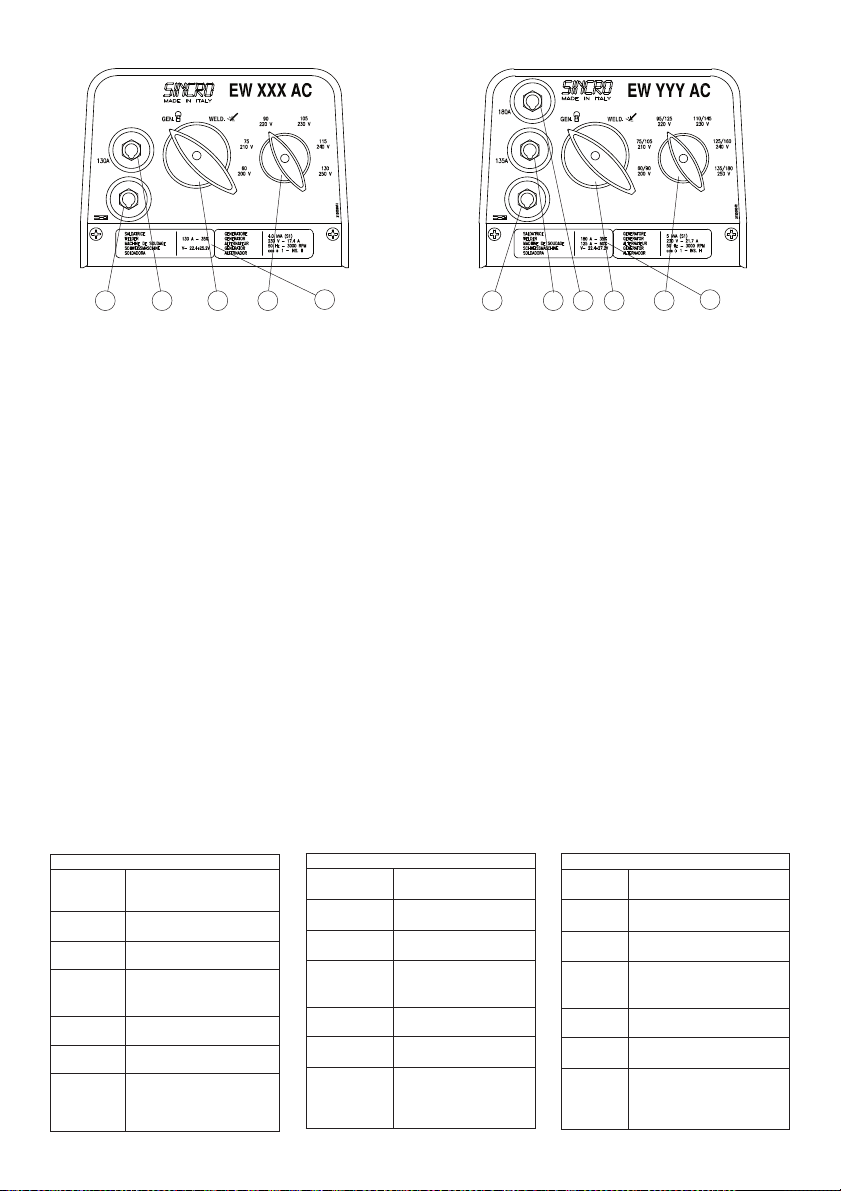
MODALITA’ DI UTILIZZO
DESCRIZIONE DEL PANNELLO
1 -Presa per la massa
2 -Presa per saldatura gamma bassa(*)
3 -Presa per saldatura gamma alta
4 -Selettore modalità di funzionamento
5 -Selettore del valore nominale
FUNZIONAMENTO COME GENERATORE
Posizionare il selettore 4 su “GEN.”.
Posizionare il selettore 5sulla tensione desi-
derata.
Collegare l’utilizzatore alle prese.
Avviare il dispositivo utilizzatore.
FUNZIONAMENTO COME SALDATRICE
Posizionare il selettore 4 su “WELD”.
Inserire lo spinotto del cavo di massa nella
presa 1.
Collegare il cavo di massa al pezzo da saldare.
Inserire lo spinotto del cavo dalla pinza portaelet-
trodo nella presa 2(*) o 3 a seconda della gamma
di corrente desiderata.
Impostare la corrente di saldatura mediante il
selettore 5 (scala blu per la gamma bassa(*), scala
rossa per la gamma alta).
Saldare.
Attenzione: la saldatrice è costruita in maniera
tale da poter erogare la corrente massima solo
per un tempo limitato, trascorso il quale necessita
un raffreddamento (vedi l’indicazione 6 in targa).
Se pertanto, lavorando con correnti elevate,
intervenisse la protezione termica, occorre atten-
dere qualche minuto per il ripristino automatico
della stessa.
(*) Non disponibile nei modelli EW 130 AC e
EW 140 AC.
USING PROCEDURE
PANEL DESCRIPTION
1 -Earth socket
2 -Socket for low range welding (*)
3 -Socket for high range welding
4 -Function mode selector
5 -Rated value selector
OPERATION AS A GENERATOR
Turn selector 4 to “GEN.”.
Turn selector 5 to the desired voltage.
Connect the user to the sockets.
Start the user device.
OPERATION AS A WELDER
Turn selector 4 to “WELD”.
Insert the jack of the earth cable in the socket 1.
Connect the earth cable to the part that is to
be welded.
Insert the jack of the cable from the electrode
holder in socket 2(*) or 3 depending on the current
range desired.
Set the welding current with the selector 5 (blue
scale for the low range(*), red scale for the high
range).
Weld.
Attention: the welding machine is made in such
a way as to give the maximum current only for
a limited time, after which it must be allowed to
cool (see indication 6 on the plate). So, when
workingwithhighcurrents,ifthethermalprotection
trips, you must wait a few minutes for it to be set
automatically.
(*) Not available on models EW 130 AC and
EW 140 AC.
MODE D’EMPLOI
DESCRIPTION DU TABLEAU
1 -Prise pour la mise à la masse
2 -Prise pour soudage gamme basse(*)
3 -Prise pour soudage gamme haute
4 -Sélecteur du mode de fonctionnement
5 -Sélecteur de la valeur nominale
FONCTIONNEMENT COMME GÉNÉRATEUR
Positionner le sélecteur 4 sur “GEN.”.
Positionner le sélecteur 5 sur la tension désirée.
Connecter le dispositif utilisateur aux prises.
Mettre en marche le dispositif utilisateur.
FONCTIONNEMENT COMME SOUDEUSE
Positionner le sélecteur sur 4 “WELD”.
Introduire la fiche du câble de masse dans la
prise 1.
Connecter le câble de masse à la pièce à
souder.
Introduire la fiche du câble de la pince porte-
électrode dans la prise 2 (*) ou 3selon la gamme
de courant désirée.
Sélectionner le courant de soudage à l’aide du
sélecteur5(graduationbleuepour la gamme basse
(*), graduation rouge pour la gamme haute).
Souder.
Attention:la soudeuse est construite de manière
qu’elle ne peut produire le courant maximum que
pour une durée limitée au-delà de laquelle elle a
besoin d’un refroidissement (voir l’indication 6 sur
la plaque). Par conséquent, si le fait de travailler
avec des courants élevés provoque l’intervention
delaprotectionthermique,ilfautattendre q u elques
minutes pour que celle-ci puisse se réarmer.
(*) Non disponible dans les modèles EW 130 AC
et EW 140 AC.
1
4 321 542656
PROBLEMI DI SALDATURA
Spruzzi eccessivi Arco lungo
Corrente elevata
Incollature Arco troppo lungo
Corrente troppo bassa
Crateri Allontanamento troppo veloce
dell’elettrodo in staccata
Inclusioni Cattiva pulizia tra le passate
Cattiva distribuzione delle passate
Movimento difettoso dell’elettrodo
Insufficiente
penetrazione
Corrente di saldatura troppo bassa
Mancata scalpellatura al vertice
Soffiature e
porosità
Umidità nell’elettrodo
Arco troppo lungo
Cricche Correnti troppo elevate
Materiali sporchi
Idrogeno in saldatura (nel rivestimento
dell’elettrodo)
WELDING PROBLEMS
Too manysplashes Long arc
High current
Sticking Arc is too long
Current too low
Craters Electrode moving awaytoo fast when
removed
Inclusions Bad cleaning between passes
Bad distribution of passes
Faultyelectrode movement
Insufficient penetration Welding current too low
No chipping at root
Blowholes and porosityHumidityin the electrode
Arc is too long
Cracks Currents too high
Dirtymaterials
Hydrogen in the weld (in the coating
of the electrode)
PROBLÈMES DE SOUDURE
Projections
excessives
Arc long
Courant élevé
Collages Arc trop long
Courant trop bas
Cratères Éloignement trop rapide de l’électrode au
moment du détachement
Inclusions Nettoyage imparfait entre les passes
Mauvaise répartition des passes
Mouvement défectueuxde l’électrode
Pénétration
insuffisante
Courant de soudage trop bas
Absence de burinage au sommet
Soufflures et
porosités
Humiditédans l’électrode
Arc trop long
Criques Courants trop élevés
Matériauxsales
Hydrogène en soudage (dans l’enrobage
de l’électrode)

Restituzione macchine in riparazione
Returning machines repaired
Retour marchandises pour reparation
Rückgabe der maschinen zur reparatur
Devolución máquinas en reparación
Lo scopo della presente
schedaèassicurarealCliente
unvalidoedefficiente servizio
diassistenza.Questascheda
dovrà essere consegnata
all’utilizzatore finale da parte
del venditore locale.
PROCEDURA
Nel caso di guasti o anoma-
lie di funzionamento delle
macchine Sincro, il Cliente
è invitato ad interpellare il
nostro “Servizio Assisten-
za”telefonando allo 0445-
450500.
Se, dopo tale contatto, risul-
tasse necessaria la restitu-
zione del prodotto, il nostro
“Servizio Assistenza”fornirà
alClienteunnumerodi“Rien-
tro Materiale Autorizzato”
(RMA),che dovrà essere
riportato sia sui documenti
di accompagnamento del
materiale che nella presente
Scheda di Riparazione.
Prodotti resi senza aver
seguito la descritta proce-
dura e privi della scheda di
riparazione,verrannorespinti
al mittente dal magazzino
accettazione.
Per l’eventuale concessione
dellagaranziaèindispensabi-
le che la Sincro sia contattata
esclusivamente dal proprio
Cliente.Richiestediriparazio-
ne provenienti direttamente
dall’utilizzatorefinale saranno
inognicasoconsiderateNON
in garanzia.
Prima di procedere a ripa-
razioni verrà comunicato
un preventivo e si attenderà
l’autorizzazione da parte
del Cliente
SCHEDA DI
RIPARAZIONE
Laschedadiriparazionedeve
essere compilata per ogni
prodotto ed inclusa nell’im-
ballo di restituzione. L’accu-
ratezza nella compilazione
renderà il nostro intervento
rapido e risolutivo.
SPEDIZIONE
La merce resa viaggia esclu-
sivamente a spese e a rischio
delClienteindipendentemen-
te dalla concessione dell’in-
tervento in garanzia.
Curarechelemacchinesiano
in ordine, pulite e che l’olio di
eventuali moltiplicatori di giri
sia stato vuotato.
Si raccomanda di restituire
il materiale entro un imballo
adeguato curando di proteg-
gere il prodotto dagli urti.
The scope of this card is
to ensure the client with a
validand efficient assistance
service. This card must be
given to the purchaser by
the local dealer.
PROCEDURE
WheneveranySincromachi-
ne malfunctions, the client
is invited to contact our
“Assistance Service”by
calling ++39 0445 450500.
If the decision is made to
return the product, we will
provide you with an “Au-
thorized Material Return”
(RMA) number that must be
included both in the delivery
documents that accompany
the material and this Repair
Card. Products that have
been returned without fol-
lowing the procedure above
andwithoutaRepairCard will
be returned to sender.
In order to obtain coverage
under the warranty, Sincro
must be contacted exclusi-
velybyits authorized dealer.
Requestsforrepairsreceived
directlyfromfinaluser clients
willbeconsideredoutsidethe
terms of warrantycoverage.
Prior to performing repair,
an estimate will be provided
and authorization must be
received from the authorized
dealer before proceeding
with the repair.
REPAIR CARD
A repair card must be com-
piled for everyproduct and
enclosed in the packaged
product sent for repair. Pro-
vidingaccurateandcomplete
information in the Repair
Card will help us repair the
product faster and better.
SHIPMENT
Allproductstoberepaired are
shippedattheriskandexpen-
se of the client regardless of
whether warrantycoverage
will be claimed or not. The
client must make sure that
the machines sent for repair
are in good order, clean, and
that the oil in the overgear
system has been drained.
Werecommendreturning the
products in adequate packa-
ging that ensures protection
against impact.
Le but de la présente fiche
est d’assurer au client un
service après-vente rapi-
de et efficace. Cette fiche
devra être communiquéà
l’utilisateur fi n al de la part
du revendeur agréé.
PROCEDURE
En cas de pannes ou d’ano-
malies de fonctionnement
des machines Sincro, le
client est invitéà contacter
notre “Service Assistance”
en téléphonant au ++39
0445 450500. Si à la suite
dececontact,larestitutiondu
produit s’avère nécessaire,
notre “Service Assistance”
communiquera au client un
numéro pour le “Retour Ma-
tériel Autorisé” (RMA) qui
devra être reportésur le do-
cument d’accompagnement
du matériel comme sur la
présente Fiche technique de
réparation.
Les produits rendus sans
avoir suivi la procédure
décrite et privés de la Fiche
technique de réparation
seront retournés à l’en-
voyeur. Pour une éventuelle
concession de garantie il est
indispensable que la Sincro
soit contactédirectement
par le revendeur agréé. Les
demandes de réparation ef-
fectuées par l’utilisateur final
seront considérées comme
étant hors garantie. Tou te
demande de réparation fera
l’objet d’un devis.
FICHE TECHNIQUE DE
REPARATION
La fiche technique de répa-
ration doit être remplie pour
chacun des produits et jointe
à la marchandise restituée.
La clartédes données four-
nies permettra une interven-
tion rapide et décisive.
EXPEDITION
Les frais d’expédition sont à
la charge du client et cela,
indépendamment du fait
que la marchandise soit
encore sous garantie. Faire
en sorte que les machines
soientau complet, nettoyées
et que l’huile des éventuels
multiplicateurs de tours ait
étéévacuée. Il est conseillé
d’expédier la machine dans
un emballage adaptéet
antichoc.
Zweckdieser Karte ist, dem
Kunden einen guten und wirk-
samen Kundendienst zu
gewährleisten. Diese Karte
soll dem Endbenutzer vom
lokalen Verkäufer übergeben
werden.
VERFAHREN
Bei Schäden oder Betriebsstö-
rungen der Sincro-Maschinen,
ist der Kunde gebeten, unse-
ren “Kundendienst”unter der
Nummer ++39 0445
450500
anzurufen.
Falls nach dieser Kontaktauf-
nahme eine Rückgabe des
Produktserforderlichsein sollte,
gibt unser “Kundendienst”dem
Kunden eine “Nummer für die
Rückgabe von autorisiertem
Material” (RMA), die sowohl
in die Begleitunterlagen des
Materials als auch in diese
Reparaturkarte einzutragen
ist. Produkte, die ohne o.g.
Vorgang und ohne Reparatur-
karte zurückgegeben werden,
werden nicht akzeptiert und
von der Annahmestelle an den
Absender zurückgegeben.Für
eineeventuelleGarantiegewäh-
rung is t es erforderlich, daßdie
Fa. Sincro ausschließlich vom
Kunden selbst kontaktiert wird.
Vom Endbenutzer gemachte
Reparaturanfragen werden
in jedem Fall als NICHT un-
ter Garantie stehende Fälle
bearbeitet.
Vor der Reparaturausführung
wird ein Kostenvoranschlag
mitgeteilt und eine Geneh-
migung seitens des Kunden
abgewartet.
REPARATURKARTE
Die Reparaturkarten müsen für
jedesProduktausgefülltwerden
und in der Rückgabever-pa-
ckung eingeschlossen sein.
Die sorgfältige Ausfüllung
ermöglich einen unserseitigen
raschen und problemlösenden
Eingriff.
VERSAND
Unabhängig von der Gewäh-
rung des Garantieeingriffs,
reist die zurückgegebene Ware
ausschließlich auf Kosten und
RisikendesKunden.Sichüber-
zeugen, daßdie Maschinen
in Ordnung und sauber sind
und daßdas Öl eventueller
Drehzahlübersetzerausgeleert
wurde.
Es wird empfohlen, das Ma-
terial in einer entsprechend
geeigneten Verpackung zu-
rückzugeben, um das Produkt
vor Stößen zu schützen.
EstafichaseremitealCliente
conlafinalidaddegarantizar-
leunserviciodepostventa vá-
lidoyeficiente.Elrevendedor
local tiene que suministrarla
al usuario final.
PROCEDIMIENTO
En caso de averías o ano-
malías de funcionamiento
de las máquinas Sincro,
aconsejamos al Cliente que
se ponga en contacto con el
Servicio Postventa llamando
elnúmero++39 0 445450500.
Si a continuación de la llama-
dafueranecesariodevolverel
producto, el Servicio de Pos-
tventa suministraráal Cl iente
un número de “Regreso Ma-
terial Autorizado” (RMA),
que deberáencontrarse
tanto en los documentos
de expedición del material,
como en la presente Ficha
de Reparación.
Productos devueltos sin ha-
berefectuadoelprocedimien-
to descrito anteriormente y
los que no tengan la ficha
dereparación,serechazarán
al Cliente del Almacén de
aceptación.
Por lo que respecta a la
posible concesión de la ga-
rantía, es preciso que Sincro
se contacte únicamente por
el Cliente; la petición de
reparaciones directamente
por parte del usuario final
han de considerarse NON en
garantía.Antes de proceder a
la reparación se comunicará
un presupuesto al Cliente y
se esperarála autorización
del mismo.
FICHA DE REPARACIÓN
La ficha de reparación debe
completarse para cada
producto e incluirse en el
embalaje de devolución. La
esmeradacompletacióndela
fi c hapermitiráunareparación
rápida yeficiente.
ENVÍO
Los gastos de transporte
correnporcuentayriesgodel
Cliente,independientemente
delaconcesiónde la interven-
ción en garantía.
Cerciorarsedequelasmáqui-
nas están limpias yen buen
estado, yque el aceite de
los posibles multiplicadores
de vueltas ha sido vaciado.
Aconsejamos devolver el
material en un embalaje que
permita protegerlo durante el
transporte.
Scheda di riparazione:
Repair card:
Fiche technique de réparation:
Reparaturkarte:
Ficha de reparación:
DATA:
Descrizione del prodotto:
Description of product:
Description du produit:
Produktbezeichnung:
Descripción del producto:
Modello:
Model:
Modèle:
Modell:
Modelo:
Matricola:
Serial number:
N° de série:
Kennummer:
Matrícula:
RMA:
Motivo della restituzione:
Reason for return::
Motif(s) de la restitution:
Begründung d. Rückgabe:
Motivo de la devolución:
Assenza di tensione:
No voltage:
Absence de tension:
Spannungsmangel:
Falta de tensión:
Tensione bassa:
Low voltage:
Tension insuffisante:
Niederspannung
Tensión baja:
Problemi meccanici:
Mechanical problems:
Problèmes mécaniques:
Mechanische Probleme:
Problemas mecánicos:
Note:
Notes:
Remarques:
Anmerkungen:
Notas:
Ditta:
Company:
Entreprise:
Firma:
Empresa:
Tel/Fax:
Persona da contattare:
Contact person:
Contact:
Ansprechpartner:
Persona a contactar:
Barrare la casella corrispondente:
Put an “X” in the corresponding box:
Barrer la case correspondante:
Das entsprechende Kästchen ankreuzen:
Rellenar la casilla correspondiente:
Riparazione:
Repair:
Réparation:
Reparatur:
Reparación:
Manutenzione:
Maintenance:
Entretien:
Wartung:
Mantenimiento:
Problemi sul quadretto elettrico:
Electrical control panel problems:
Problème au niveau des circuits électriques:
Probleme am Schaltbrett:
Problemas en el cuadro eléctrico:
Tensione alta:
High voltage:
Surtension:
Hochspannung:
Tensión alta:
IDENTIFICAZIONE CLIENTE - CLIENT IDENTIFICATION - DONNEES D’IDENTIFICATION CLIENT -
KUNDENBEZEICHNUNG - IDENTIFICACIÓN DEL CLIENTE
Tecnico contattato:
Technician contacted:
Technicien contacté:
Kontaktierter Techniker:
Técnico contactado:
SINCRO s.r.l. - Via Tezze, 336073Cereda di Cornedo Vicentino Vicenza - Italy-
ph. +39 0445 450500 - fax. +39 0445 446222

GARANZIA
La Sincro s.r.l garantisce ai
propri clienti gli alternatori
e saldatrici prodotti al suo
interno per un periodo di 12
mesi a decorrere dalla data
di consegna. Si precisa che
detta garanzia è rivolta ai
soli clienti della Sincro ai
quali direttamente risponde.
La Sincro non riconosce
direttamente la garanzia
ad alcun soggetto che,
pur in possesso dei suoi
prodotti, non li abbia da essa
acquistati direttamente.
Entro i suddetti termini la
Sincro si impegna a fornire
gratuitamente pezzi di
ricambio di quelle parti che,
a giudizio della Sincro o
di un suo rappresentante
autorizzato, presentino
difetti di fabbricazione o di
materiale oppure, a suo
giudizio, ad effettuarne la
riparazione direttamente
o per mezzo di officine
autorizzate senza assumersi
alcun onere per il trasporto.
Rimane comunque
esclusa qualsiasi altra
forma di responsabilità o
obbligazione per altre spese,
danni e perdite dirette o
indirette derivanti dall’uso
o dalla impossibilità d’uso
dei prodotti, sia totale che
parziale.
La riparazione o la fornitura
sostitutiva non prolungherà,
né rinnoverà la durata del
periodo di garanzia.
La garanzia decadrà:
qualora si manifestassero
inconvenienti o guasti dovuti
ad imperizia, utilizzo oltre
ai limiti delle prestazioni
nominali, se il prodotto
avesse subito modifiche
o se dovesse ritornare
disassemblato o con dati di
targa alterati o manomessi.
Per la richiesta di garanzia
i clienti dovranno attenersi
alla procedura descritta
nella scheda gialla
allegata al manuale d’uso
e manutenzione che, per
la resa del materiale,
dovrà accompagnare ogni
prodotto.
GARANTIE
Die Firma Sincro s.r.l gewährt
ihren Kunden eine Garantie
von 12 Monaten Laufzeit ab
dem Auslieferungsdatum auf
die in ihrem Betrieb hergestell-
ten Drehstromgeneratoren
und Schweißmaschinen. Es
wird präzisiert, dass diese
Garantie ausschließlich für
die Kunden der Firma Sincro,
denen gegenüber sie direkt
haftet, bestimmt ist. Die Firma
Sincro erkennt keine direkte
Garantie gegenüber Perso-
nen/Firmen an, die, obwohl
sie im Besitz ihrer Produkte
sind, diese nicht direkt von
ihr gekauft haben.
Die Firma Sincro verpflichtet
sich, innerhalb der oben ge-
nannten Fristen kostenlos
Ersatzteile für jene Teile zu
liefern, die ihrem eigenen
Urteil oder dem eines von
ihr autorisierten Vertreters
gemäß Fabrikations- oder
Materialmängel aufweisen,
oder, wenn sie dies für richtig
hält, die Reparatur direkt oder
mittels autorisierter Werkstät-
ten auszuführen, wobei sie
keinerlei Transportaufwen-
dungen übernimmt.
Ausgeschlossen bleibt jedoch
jegliche sonstige Form der
Haftung oder Verpflichtung
in Bezug auf anderweitige
Kosten, Schäden und direk-
te oder indirekte Verluste,
die sich aus dem Gebrauch
oder aus der Unmöglichkeit
des Gebrauchs der Produkte
ableiten, sei es in vollem
Umfang oder teilweise.
Die Reparatur oder Ersa-
tzlieferung bewirkt weder
eine Verlängerung noch eine
Erneuerung der Laufzeit der
Garantie.
Die Garantie verfällt, wenn
Probleme oder Störungen
auftreten, die durch unsa-
chgemäßen Gebrauch ent-
stehen, bei Einsatz über die
Nennleistungsgrenzen hinaus,
wenn am Produkt Abänderun-
gen vorgenommen wurden
oder wenn es in zerlegtem
Zustand oder mit veränderten
bzw. manipulierten Daten des
Typenschilds zurückgesandt
werden sollte.
Zur Beantragung von Ga-
rantieleistungen müssen die
Kunden sich an den Ver-
fahrensablauf halten, der im
gelben Datenblatt, das der
Bedienungs- und Wartung-
sanleitung beigefügt ist und
das bei Materialrücksendung
jedes Produkt begleiten muss,
beschrieben ist.
GARANTIE
Sincro s.r.l garantit à ses
clients les alternateurs et
les machines à souder pro-
duites par ses soins pour
une période de 12 mois
à compter de la date de
livraison. Nous précisons
que cette garantie est accor-
dée uniquement aux clients
de Sincro auxquels elle
répond directement. Sincro
ne reconnaît directement la
garantie à aucun sujet qui,
tout en possédant l’un de
ses produits, ne le lui a pas
acheté directement.
Dans les périodes susdites,
Sincro s’engage à fournir
gratuitement les pièces de
rechange des parties qui, de
l’avis de Sincro ou de l’un de
ses représentants agréés,
présentent des défauts de
fabrication ou de matériau
ou bien, selon son jugement,
elle s’engage à en effectuer
la réparation directement
ou par le biais d’ateliers
agréés sans prendre à sa
charge aucun frais pour le
transport.
Toute autre forme de res-
ponsabilitéou obligation
pour d’autres frais, dom-
mages ou pertes directes
et indirectes dérivant de
l’utilisation ou de l’impossibi-
litéd’utilisation des produits,
tant partielle que totale,
reste exclue.
La réparation ou le rempla-
cement du produit ne prolon-
geront ni ne renouvelleront
la période de garantie.
La garantie ne sera pas
applicable en cas de pannes
ou d’inconvénients dus à
l’inexpérience, à l’utilisa-
tion au-delà des limites des
performances nominales, si
le produit a subi des modi-
fi c ations ou s’il est retourné
démontéou avec des don-
nées de plaque altérées ou
modifiées.
Pour la demande de
garantie, les clients devront
suivre la procédure décrite
dans la fiche jaune jointe
au manuel d’instructions
et de maintenance qui de-
vra accompagner chaque
produit en cas de retour de
matériel.
GARANTÍA
Sincro s.r.l garantiza a sus
clientes los alternadores
ysoldadoras de su
fabricación por un periodo
de 12 meses a partir de
la fecha de entrega. Se
especifica que Sincro
reconoce exclusivamente
la garantía que ampara
solo a sus propios clientes,
ante los que se hace
directamente responsable.
Sincro no reconoce
directamente la garantía a
ningún sujeto que, a pesar
de estar en posesión de
sus productos, no los haya
adquirido directamente de
ella.
Dentro de los términos
establecidos Sincro se
obliga a proporcionar
gratuitamente piezas de
recambio de las partes
que, según el juicio de
la empresa Sincro o de
un representante suyo
autorizado, tengan defectos
de fabricación o del material,
o bien, según su juicio,
a efectuar la reparación
directamente o por medio
de talleres autorizados, sin
correr con ningún gasto por
el transporte.
De cualquier modo, queda
excluida toda otra forma
de responsabilidad u
obligación por otros gastos,
daños ypérdidas directas o
indirectas que deriven del
uso o de la imposibilidad
de utilizar en todo o en parte
los productos.
La reparación o el suministro
sustitutivo no prolongaráni
renovarála duración del
periodo de garantía.
La garantía se
invalidaráen el caso
de que se manifestaran
inconvenientes o averías
debidos a incompetencia
o a un uso que supere los
límites de las prestaciones
nominales, asícomo en
el caso de modificaciones
aportadas al producto o de
devolución con el artículo
desensamblado o con las
características nominales
alteradas o manipuladas.
Para solicitar la garantía, los
clientes deberán atenerse
al procedimiento descrito
en la ficha amarilla que
se adjunta con el manual
de uso ymantenimiento
yque deberáacompañar
el material en el caso de
devolución.
WARRANTY
Sincro S.r.l. guarantees the
own alternators and welders
for a period of 12 months
starting from the invoice
issue date. We confirm that
warrantyis directed only
to Sincro customers to
which we respond. Sincro
does not grant warrantyto
those who have not directly
purchased the product from
the factory, in spite of the
possession of it.
Within the above mentioned
terms, Sincro commits itself
to supplyfree of charge
those spare parts that,
according to its judgment or
to the one of an authorized
representative, appear with
manufacturing or material
defects or, always to its ju-
dgment,todirectlyor th rough
an authorized centre carry
out the repairing without un-
dertaking transport costs.
We anyhowexclude forms
ofresponsibilityor obligation
forothercosts,damages and
direct or indirect loss caused
bythe total or partial usage
or impossible usage of the
products.
Therepairingorthesubstitu-
tion will not extend or renew
the warrantyduration.
Warrantywill not be granted:
whenever break-downs or
problems mayappear be-
cause of lackof experience,
usage over the nominal
performances, if the product
had been modified or should
return incomplete, disas-
sembled or with modified
nameplate data.
Forthewarrantyrequest,the
customers must followthe
procedure described on the
yellowcard included in the
user’s manual, which is sup-
plied with each product.

La lista dei centri assistenza autorizzati si trova nel nostro sito web : www.sogagroup.com
The service center list is available in our web site : www.sogagroup.com
La liste des centres de service après-vente agréés se trouve sur notre site web: www.sogagroup.com
Die Liste unserer autorisierten Kundendienststellen ndet sich aufunsererWebsite: www.sogagroup.com
Uds. encontrarán la lista de los centros de asistencia autorizados en nuestro sitio web: www.sogagroup.com

BENUTZUNGSMODALITÄTEN
BESCHREIBUNG DER STEUERTAFEL
1 -Steckdose für Erdung
2 -Steckdose für Schweißvorgang Niedrigbe-
reich(*)
3 -Steckdose für Schweißvorgang hoher
Bereich
4 -Wählschalter für Betriebsmodus
5 -Wählschalter für Nennwert
BETRIEB ALS GENERATOR
Den Wählschalter 4 auf “GEN.” stellen.
Den Wählschalter 5 auf die gewünschte Span-
nung stellen.
Den Benutzer mit den Steckdosen verbinden.
Die Benutzervorrichtung starten.
BETRIEB ALS SCHWEISSMASCHINE
Den Wählschalter 4 auf “WELD” stellen.
Den Steckerstift des Erdungskabels in die Ste-
ckdose 1 einführen.
Das Erdungskabel mit dem zu schweißenden
Werkstück verbinden.
Den Steckerstift des aus der Elektrodenhalterzan-
ge herauskommenden Kabels in die Steckdose
2(*) oder 3einführen, je nach gewünschtem
Strombereich.
DenSchweißstromüberdenWählschalter 5( b laue
Skala für Niedrigbereich(*), rote Skala für hohen
Bereich) einstellen.
Schweißen.
Achtung: Die Schweißmaschine ist so konstruiert,
daß sie den Höchststrom nur für einen begrenzten
Zeitraum liefern kann, nach dessen Ablauf eine
Abkühlung erforderlich ist (siehe Hinweis 6 auf
dem Typenschild). Sollte daher, wenn man mit
hohen Stromwerten arbeitet, der Thermoschutz
eingreifen, muß man einige Minuten warten, bis
COMO SE UTILIZA
DESCRIPCION DEL PANEL
1 -Toma para la masa
2 -Toma para la soldadura de gama baja (*)
3 -Toma para la soldadura de gama alta
4 -Mando de modalidad funcionamiento
5 -Mando del valor nominal
FUNCIONAMIENTO COMO GENERADOR
Posicionar el mando 4 en “GEN.”.
Posicionar el mando 5 en la tensión deseada.
Conectar el utilizador a las tomas.
Poner en marcha el dispositivo utilizador.
FUNCIONAMIENTO COMO SOLDADORA
Posicionar el mando 4 en “WELD”.
Meter el enchufe del cable de masa en la
toma 1.
Conectar el cable de masa en la pieza a soldar.
Meter el enchufe del cable de la pinza portae-
lectrodo en la toma 2(*) o 3 conforme a la gama
de corriente deseada.
Programar la corriente de soldadura con el mando
5(escala azul oscuro para la gama baja(*), escala
roja para la gama alta).
Soldar.
Atención: la soldadora está construida de forma
que pueda suministrar la corriente máxima sólo en
tiempo limitado, al transcurrir el cual es necesario
enfriarla (ver la indicación 6 de la placa). Así, si al
trabajarconcorrienteselevadasse activa la protec-
cióntérmica,hayqueesperarunosminutosparala
puesta en marcha automática del aparato.
(*) No disponible en los modelos EW 130 AC y
EW 140 AC.
dieser sich automatisch rückgestellt hat.
(*) Nicht verfügbar bei den Modellen EW 130 AC
und EW 140 AC.
1
4 321 542 65 6
PROBLEMAS DE SOLDADURA
Excesivas
salpicaduras
Arco largo
Corriente elevada
Pegados Arco demasiado largo
Corriente demasiado baja
Cráteres Separación demasiado rápida del
electrodo al alejarlo
Inclusiones
Entre las pasadas no se limpia bien
Mala distribución de las pasadas
Movimiento defectuoso del electrodo
Insuficiente
penetración
Velocidad de avance demasiado alta
Corriente de soldadura demasiado
baja
Cincel de calafatear estrecho
Cinceladura no efectuada en el
vértice
Soplados y
porosidad
Humedad en el electrodo
Arco demasiado largo
Grietas
Corrientes demasiado elevadas
Materiales sucios
Hidrógeno en soldadura (en el
revestimiento del electrodo)
SCHWEISSPROBLEME
Übermäßiges
Sprühen
Langer Lichtbogen
Starker Strom
Ankleben Lichtbogen zu lang
Strom zu niedrig
Krater Zu schnelles Entfernen der Elektrode
beim Ablösen
Einschlüsse
Unzureichende Reinigung zwischen
den Schweißgängen
Unzureichende Verteilung der
Schweißgänge
Fehlerhafte Bewegung der Elektrode
Unzureichende
Durchdringung
Annäherungsgeschwindigkeit zu hoch
Schweißstrom zu niedrig
Schmaler Stemm-Meißel
Kein Abmeißeln am Scheitel
Blasen und
Porösität
Feuchtigkeit in der Elektrode
Lichtbogen zu lang
Risse
Zu hoher Strom
Schmutzige Materialien
Wasserstoff in der Schweißung (im
Überzug der Elektrode)
CARATTERISTICHE MAIN FEATURES CARACTERISTIQUES EIGENSCHAFTEN CARACTERISTICAS EW 130 AC EW 180 AC EW200 AC EW140 AC EW190 AC EW220 AC
VELOCITA’ SPEED VITESSE DREHZAHL VELOCIDAD 3000 r.p.m.
H
IP21
32 kg
3000 r.p.m.
H
IP21
37 kg
3000 r.p.m.
H
IP21
42 kg
3600 r.p.m.
H
IP21
32kg
3600 r.p.m.
H
IP21
37kg
3600 r.p.m.
H
IP21
42kg
CLASSE D’ ISOLAM. INSULATION CLASS ISOLEMENT ISOLATIONSKLASSE AISLAMIENTO
PROTEZIONE PROTECTION PROTECTION SCHÜTZ PROTECCION
PESO (IM B35) WEIGHT (IM B35) POIDS (IM B35) GEWIGHT (IM B35) PESO (IM B35)
SALDATRICE WELDER MACHINE DE SCHWEISS- SOLDADORA POS. I V I I V I I V I V I I V I I V
SOUDAGE MASCHINE min max min max min max min max
CORRENTE DI WELDING CURRENT COUR. DE SOUDAGE SCHWEISSTROM UND CORRIENTE DE 1 60 200 60 90 200 60 120 180 60 200 60 100 190 60 120 180
SALDATURA E AND ALTERNATOR ET TENSION DE SPANNUNG DES SOLDADURA Y 2 75 210 75 105 210 75 130 190 75 210 75 125 200 75 130 190
TENSIONE DEL VOLTAGE IN THE L’ALTERNATEUR GENERATORES VOLTAJE DE EL 3 90 220 90 125 220 85 145 200 90 220 90 140 210 85 140 200
GENERATORE DIFFERENT DANS LES IN DEN ALTERNADOR EN 4 105 230 110 145 230 100 155 210 105 230 105 155 220 100 160 210
NELLE VARIE SELECTOR DIFFERENT VERSCHIEDENEN LAS DIFERENTES 5 115 240 120 160 240 115 165 220 120 240 120 170 230 115 180 220
POSIZIONI POSITIONS POSITIONS STELLUNGEN POSICIONES 6 130 250 135 180 250 125 180 230 140 250 135 190 240 125 200 230
7 135 200 240 135 220 240
FULL
LOAD
NO
LOAD
FULL
LOAD
FULL
LOAD
NO
LOAD
FULL
LOAD
FULL
LOAD
NO
LOAD
FULL
LOAD
NO
LOAD
FULL
LOAD
FULL
LOAD
NO
LOAD
FULL
LOAD
FULL
LOAD
NO
LOAD
VVmin max Vmin max VVVmin max Vmin max V
TENSIONE DI FULL LOAD TENSION DE SOUDAGE SCHWEISPANNUNG VOLTAJE DE 1 22,4 50 22,4 23,6 50 22,4 24,8 45 22,4 50 22,4 24 47,5 22,4 24,8 45
SALDATURA AND NO LOAD EN CHARGE BEI VOLLAST SOLDADURA 2 23 52,5 23 24,2 52,5 23 25,2 47,5 23 52,5 23 25 50 23 25,2 47,5
A CARICO WELDING VOLTAGE ET A VIDE UND LEERLAUF DE CARGA 3 23,6 55 23,6 25 55 23,4 25,8 50 23,6 55 23,6 25,6 52,5 23,4 25,6 50
E A VUOTO IN THE DIFFERENT DANS LES IN DEN Y EN VACÌO EN 4 24,2 57,5 24,4 25,8 57,5 24 26,2 52,5 24,2 57,5 24,2 26,2 55 24 26,4 52,5
NELLE VARIE SELECTOR DIFFERENT VERSCHIEDENEN LAS DIFERENTES 5 24,6 60 24,8 26,4 60 24,6 26,6 55 24,8 60 24,8 26,8 57,5 24,6 27,2 55
POSIZIONI POSITIONS POSITIONS STELLUNGEN POSICIONES 6 25,2 62,5 25,4 27,2 62,5 25 27,2 57,5 25,6 62,5 25,4 27,6 60 25 28 57,5
7 25,4 28 60 25,4 28,8 60
TIPO DI ELETTRODI
SALDABILI: RUTILE
WELDABLE
ELECTRODES: RUTILE
TYPE ELECTRODES
SOUDABLE: RUTILE
TYPE ELEKTRODE
SCHWEISSBAR: RUTIL
TIPO ELECTRODOS
SOLDABLE: RUTILE
SERVIZIO DUTY SERVICE DIENST SERVICIO 130 A - 35% 180 A - 35%
125 A - 60%
200 A - 35%
180 A - 60% 140 A - 35% 190 A - 35%
135 A - 60%
220 A - 35%
180 A - 60%
POTENZA DRIVING PUISSANCE LEISTUNGS- POTENCIA 6kW - 8,5Hp
(3000 r.p.m.)
8kW - 11 Hp
(3000 r.p.m.)
9kW - 12 Hp
(3000 r.p.m.)
6,5kW - 9HP
(3600 r.p.m.)
9kW - 12 Hp
(3600 r.p.m.)
9,5kW - 13Hp
(3600 r.p.m.)
ASSORBITA POWER ABSORBEE AUFNAMME ABSORBIDA
GENERATORE ALTERNATOR ALTERNATEUR GENERATOR ALTERNADOR
MONOFASE SINGLE PHASE MONOPHASE EINPHASIGER MONOFASICO
POTENZA POWER PUISSANCE LEISTUNG POTENCIA 4 kVA (S1) 5 kVA (S1) 7 kVA (S1) 5 kVA (S1) 6 kVA (S1) 8 KVA (S1)
TENSIONE
(REGOLABILE)
VOLTAGE
(ADJUSTABLE)
TENSION
(REGLABLE)
SPANNUNG
(REGULIERBAR)
TENSION
(REGULABLE) 115-230 V 115-230 V 115-230 V 120-240 V 120-240 V 120-240 V
CORRENTE (MAX S1) CURRENT (MAX S1) COURANT (MAX S1) STROM (MAX S1) CORRIENTE (MAX S1) 17,4 A 21,7 A 30,4 A 20,8 A 25 A 33,3 A
FREQUENZA FREQUENCY FREQUENCE FREQUENZ FREQUENCIA 50 Hz 50Hz 50Hz 60Hz 60Hz 60Hz
La saldatrice è fornita
di protezione termica
autoripristinabile contro
i sovraccarichi.
The welder is supplied
with thermal breaker
(autoresettable) against
overload.
La machine est protegèe
avec un dispositive
thermique (avec
retablissement).
Die Schweissmaschine
ist mit einem
Überlastungsschutz
geliefert
La soldadora la
suministramos con
un dispositivo termico
que se restablece
automaticam.
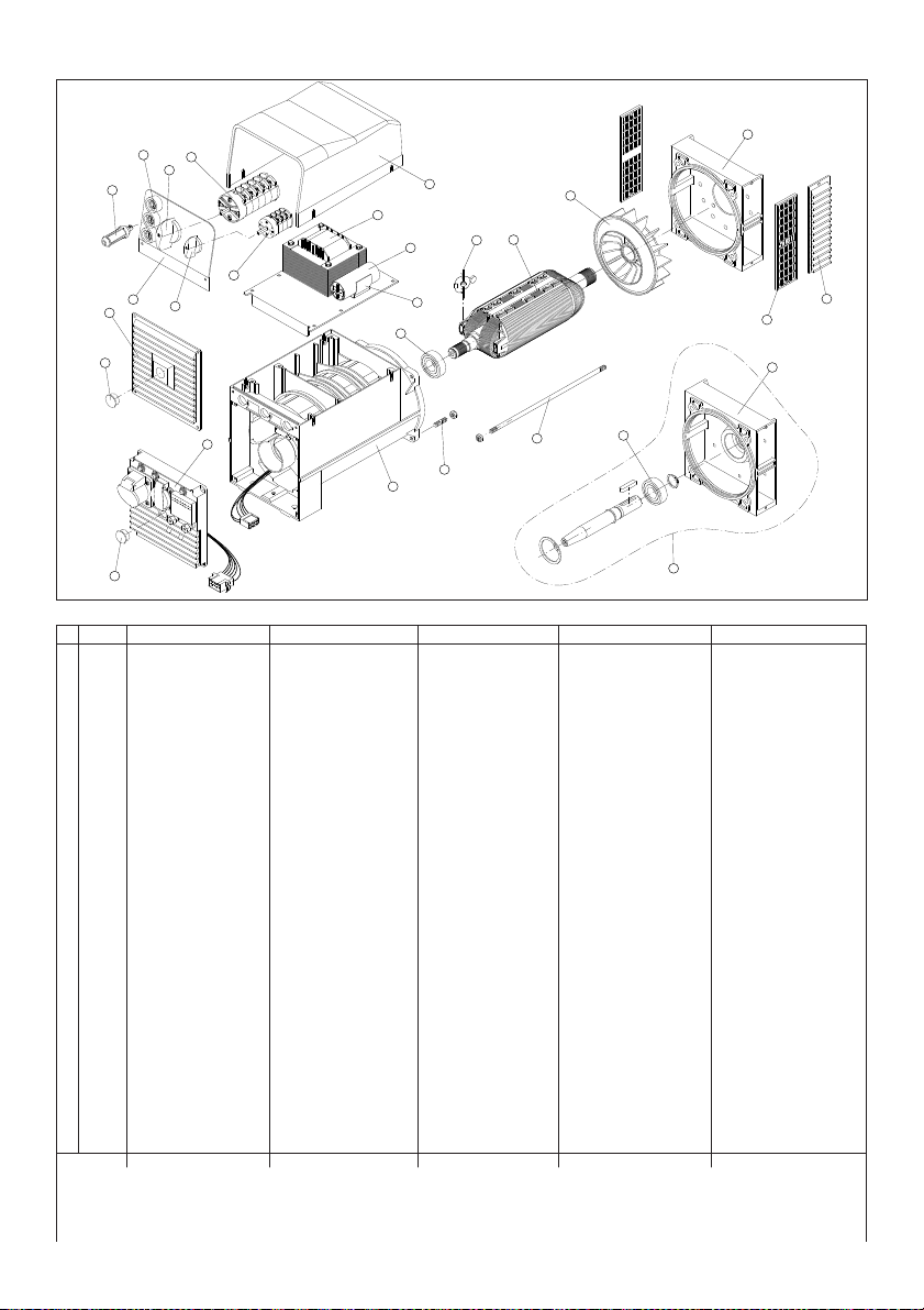
Disegno esploso Exploded view Vue eclatee Teilmontagezeichnung
Parti di ricambio Spare parts list Pieces detachees Ersatzteilliste
Despiece
Partes de recambio
15
14
13
12
16
17
18
19
20
11
10
9
8
7
65
4
3
1
2
3
25
24
22
21
23
7
26
N.RIF CODICE
SINCRO DESCRIZIONE DESCRIPTION DESCRIPTION BESCHREIBUNG DESCRIPCIÓN
1 266062001 Griglia anteriore IP21 Front grid IP21 Grille de protection antérieure IP21 Vorderes Gitter IP21 Rejilla anterior IP21
2 266042001 Griglia anteriore IP23 Front grid IP23 Grille de protection antérieure IP23 Vorderes Gitter IP23 Rejilla anterior IP23
3(*) 4061011023 Scudo anteriore “E” lav. IMB35 J609A Front shield “E” IMB35 J609A Flasque antérieur “E” IMB35 J609A Vorderer Kasten “E” IMB35 J609A Escudo anterior “E” IMB35 J609A
4061011031 Scudo anteriore “E” lav. IMB35 J609B Front shield “E” IMB35 J609B Flasque antérieur “E” IMB35 J609B Vorderer Kasten “E” IMB35 J609b Escudo anterior “E” IMB35 J609B
4061011291 Scudo anteriore “E” lav. IMB35 c.23 Front shield “E” IMB35 c.23 Flasque antérieur “E” IMB35 c.23 Vorderer Kasten “E” IMB35 c.23 Escudo anterior “E” IMB35 c.23
4061011023 Scudo anteriore “E” lav. IMB35 c.30 Front shield “E” IMB35 c.30 Flasque antérieur “E” IMB35 c.30 Vorderer Kasten “E” IMB35 c.30 Escudo anterior “E” IMB35 c.30
4061011011 Scudo anteriore “E” lav. IMB34 (B3/B14) Front shield “E” IMB34 (B3/B14) Flasque antérieur “E” IMB34 (B3/B14) Vorderer Kasten “E” IMB34 (B3/B14) Escudo anterior “E” IMB34 (B3/B14)
4(*) 266083001 Ventola (con foro f30) Fan (with hole f30) Ventilateur (avec trou f30) Lüfterrad mit Loch f 30 Ventilador agujero f30
266083002 Ventola (con foro f35) Fan (with hole f35) Ventilateur (avec trou f35) Lüfterrad mit Loch f 35 Ventilador agujero f35
5(*) 511237… Rotore EW ( Accopp. ?) (1) Rotor EW (Coupling ?) (1) Rotor EW (Accouplem. ?) (1) Rotor EW (Kupplung ?) (1) Rotor EW (Acoplamiento ?) (1)
6 79060 Diodo + Varistore + Condensatore EMC Diode + Varistor + EMC Capacitor Diode + Varistor + Condensateur EMC Diode + Varistor + Kondens.EMC Diodo + Variador + Condensador EMC
7 1750016205 Cuscinetto 6205 2RS C3 Bearing - 6205 2RS C3 Roulement - 6205 2RS C3 Lager 6205 2 RS C3 Cojinete 6205 2RS C3
8 1790052 Molla portacondensatore Capacitor block spring Ressort fixation condensateur Kondensatorhaltefeder Resorte portacondensador
9(*)3001000.. Condensat. ...mF 450V (EW130-220 AC) Capacitor ...mF 450V (EW130-220 AC) Condensat. ...mF 450V (EW130-220 AC)Kondensator ... mF 450V (EW130÷220 AC) Condensador ... mF 450V (EW130÷220 AC)
10(*)308072015A Impedenza EW130-140 AC EW130-140 AC weld. impedance Reactance EW130-140 AC Impedanz EW130-140 AC Impedancia EW130-140 AC
308072014A Impedenza EW180÷220 AC EW180÷220 AC weld. impedance Reactance EW180÷220 AC Impedanz EW180÷220 AC Impedancia EW180÷220 AC
11 266024005Coperchio ET-EW-EKM nero ET-EW-EKM blacktop cover Couvercle superieur ET-EW-EKM noir Gitterhaltedeckel ET-EW-EKM schwarz Tapa negra (ET-EW-EKM)
123035020401Commutatore 2 posiz. (GEN/WELD) 2 posit. commutator (GEN/WELD) Commutateur 2 posit. (GEN/WELD) Zweistellenschalter (GEN/WELD) Conmutador de 2 posic. (GEN/WELD)
13 Manopola commutatore (2 pos.) Commutator knob (2 pos.) Bouton de le commutateur (2 pos.) Drehknopf Umschalter (2 Pos.) Botón del conmutador (2 pos.)
14 305900200 Morsetto femmina 200A saldatura Female 200A welding terminal Borne de soudage (200A femelle) Aufnahmeklemme 200A Schweißung Borne hembra 200A soldadura
15 305901200 Morsetto maschio 200A saldatura Male 200A welding terminal Borne de soudage (200A mâle) Einsteckklemme 200A Schweißung Borne macho 200A soldadura
16(*)303506016 Commutatore 6 posiz. (EW130÷190 AC) 6 posit. commutator (EW130÷190 AC) Commutateur 6 posit. (EW130÷190 AC) Sechsstellenschalter (EW130÷190 AC) Conmutador 6 posic. (EW130÷190 AC)
303507016 Commutatore 7 posiz. (EW200-220 AC) 7 posit. commutator (EW200-220 AC) Commutateur 7 posit. (EW200-220 AC) Sechsstellenschalter (EW200-220 AC) Conmutador 6 posic.(EW200-220 AC)
17 Manopola commutatore (6-7 pos.) Commutator knob (6-7 pos.) Bouton de le commutateur (6-7 pos.) Drehknopf Umschalter (6-7 Pos.) Botón del conmutador (6-7 pos.)
18(*) 215009… Mostrina Panel Plaque Platte Placa de aluminio
19 266022004Griglia posteriore IP23GS100T IP23end cover (GS100T) Couvercle postér. aspiration IP23Hinteres Gitter IP23GS100T Rejilla trasera IP23GS 100 T
20 266064008Tappo GS100T / KS Ta p (GS100T / KS) Bouchon (GS100T / KS) Stopfen GS100T / KS Tap òn GS100T / KS
21(*) 266061004Cuffia EKcieca Blind EKend cover Couvercle post. aspiration EKsans trous EKSchutzkasten Tap a EKciega posterior
7022-- Quadretto EKmonofase (vedi...) EKsingle-phase panel (see...) Tab leau monophasè EK(voir...) Schaltbrett EKeinphasiger (siehe . . . ) Cuadro EKmonofasico (Véase...)
22 266064007 Tappo EKTa p (EK)Bouchon (EK) Stopfen EKTapòn EK
23(*) 651276…Carcassa M +Statore EWHousing M +Stator EWCarcasse M +Stator Gehäuse +Stat. EWCarcasa +Estat. EW
24 176002030Tirante M8x30 Staybolt - M8x30Tige M8x30 Spannstange M8x30Tirante M8x30
25(*)17600-- Tirante albero (dimensioni-accoppiam.?) Shaft staybolt (dimensions-coupling ?)Tige centrale (dimensions-accouplem. ?) Spannstange (Kupplungsabmessung ?)Tirante àrbol (dimens. - acoplamiento ?)
26 300005 KIT:da IMB35 J609B a IMB34 (B3/B14)KIT:from IMB35 J609B to IMB34 (B3/B14)KIT:de IMB35 J609B à IMB34 (B3/B14)KIT:von IMB35 J609B bis IMB34 (B3/B14)KIT:da IMB35 J609B a IMB34 (B3/B14)
(1) Comprende il particolare 4-6-7 (1)4-6-7 item is included (1) Comprend la piéce 4-6-7 (1)Teil 4-6-7 inbegriffen (1) Incluye el particular 4-6-7
(*) Includere nella richiesta di pezzi di ricambio la descrizione dell’oggetto, il codice, il numero di matricola e le caratteristiche della macchina (rilevabili dalla targhetta).
(*) When ordering spare parts, please indicate the alternator code-number and machine serial number and characteristics (theyare available on the label)
(*) Nous vous prions d’indiquer, dans vos commandes de pièces de rechange, la description de la pièce, le numéro de code et de série et les caractéristiques de la machine
(*) In den Ersatzteilanfrage sind die Gegenstandbeschreibung, die Materialnummer, die Kennummer und die Eigenschaften der Maschine (vom Schild zu entnehmen) anzugeben.
(*) Solicitar las piezas de recambio siempre indicando la descripción del objeto, el código, el número de matrícula ylas características de la máquina (descritas en la placa de identificación).
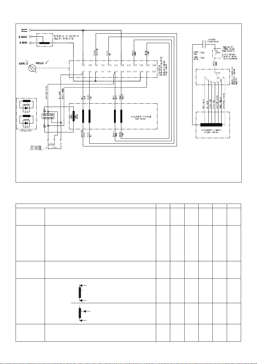
Wiring diagrams Schema electrique Schaltpläne Esquemas eléctri-Schemi elettrici
Resistenze degli
avvolgimenti a 20°C
Winding resistances
at 20°C
Résistances bobines
à 20°C
Widerstand der
Wicklung bei 20°C
Resistencias de los
bobinados a 20°
Colori
colours
couleur
farbe
color
Blu:
blue
bleu
blau
azul
Grigio:
grey
gris
grau
gris
Marrone:
brown
marron
braun
marròn
Rosso:
red rou-
ge rot
rojo
Aran-
cione:
orange
orange
orange
anaranjado
Giallo:
yellow
jaune
gelb
amarillo
Viola:
violet
violette
violett
violeta
EW 130 AC EW 180 AC EW 200 AC EW 140 AC EW 190 AC EW 220 AC
Avvolgimento principale Regolare il selettore di funzionamento in posizione “GEN”. Misurare sulla presa.
Main winding Turn the function selector to “GEN” position. Measure on the socket.
Enroulement principal Régler le sélecteur de fonctionnement sur “GEN”. Mesurer sur la prise. 1.3 Ω0.90 Ω0.53 Ω0.94 Ω0.57Ω0.40 Ω
Hauptwicklung Den Wählschalter für den Betriebsmodus auf Position “GEN” einstellen. An der Steckdose messen.
Bobinado principal Poner el mando de funcionamiento en posición “GEN”. Medir en la toma.
Avvolgimento ausiliario Regolare il selettore in posizione massima. Misurare sui fili collegati al condensatore (condensatore
non collegato).
Auxiliarywinding Turn the current selector to maximum position; measure on the wires connected to the capacitor
(disconnected capacitor).
Enroulement auxiliaire Régler le sélecteur de courant sur la position maximum. Mesurer sur les fils connectés au
condensateur (condensateur déconnecté). 2.7 Ω1.6 Ω1.4Ω1.8Ω1.1Ω0.7 Ω
Hilfswicklung Den Strom-Wählschalter in die max. Position stellen; an den mit dem Kondensator verbundenen
Drähten messen (Kondensator abgetrennt).
Bobinado auxiliario Poner el mando de corriente en posición máxima, medir en los hilos conectados al condensador
(condensador desconectado).
Rotore Misurare ai capi dei diodi.
Rotor Measure on the ends of the diodes.
Rotor Mesurer auxcosses des diodes. 2.0 Ω2.1Ω2.2 Ω2.0Ω2.1Ω2.7 Ω
Rotor An den Kopfenden der Dioden messen.
Rotor Medir en los extremos de los diodos.
Impedenza di saldatura Gamma bassa.
Lowrange.
Gamme basse.
Niedrigbereich
Gama baja.
Welding impedance 6.5mΩ6.6 mΩ6.6 mΩ6.5mΩ6.6 mΩ6.6 mΩ
Impédance de soudage
Gamma alta.
High range.
Gamme haute.
Hoher Bereich.
Gama alta.
Schweißimpedanz -- 4.3mΩ4.3mΩ-- 4.3mΩ4.3mΩ
Impedancia de soldadura
Condensatore Valori indicativi.
Capacitor Indicative values.
Condensateur Valeurs indicatives 31.5µF45 µF45-50 µF35 µF45 µF45-50 µF
Kondensator Indikative Werte.
Condensador Valores indicativos.

INCONVENIENTI CAUSE RIMEDIO
Manca tensione a vuoto. 1) Selettore di funzionamento in posizione
errata. 1) Spostare il selettore.
2) Macchina smagnetizzata. 2) Applicare ai morsetti d’uscita per 1 sec. una tensione continua
compresa tra 6 ÷12 V.
3) Velocità ridotta. 3) Controllare i giri e portarli al valore nominale.
4) Diodi rotanti difettosi. 4) Controllare e sostituire.
5) Condensatore difettoso 5) Controllare e sostituire.
6) Guasto negli avvolgimenti. 6) Controllare le resistenze degli avvolgimenti come da tabella.
Tensione a vuoto bassa. 1) Selettore di corrente in posizione errata. 1) Spostare il selettore.
Corrente di saldatura bassa. 2) Spinotto del cavo nella gamma errata. 2) Spostare lo spinotto.
3) Velocità tropo bassa. 3) Controllare la velocità e regolare.
4) Diodi rotanti difettosi. 4) Controllare e sostituire.
5) Condensatore di valore errato 5) Controllare e sostituire.
6) Avvolgimenti avariati. 6) Controllare le resistenze degli avvolgimenti come da tabella.
Tensione a vuoto troppo alta. 1) Selettore di corrente in posizione errata. 1) Spostare il selettore
Corrente di saldatura troppo alta. 2) Spinotto del cavo nella gamma errata. 2) Spostare lo spinotto.
3) Velocità motore troppo alta. 3) Controllare la velocità e regolare.
4) Condensatore di valore errato 4) Controllare e sostituire.
5) Rotore difettoso. 5) Sostituire il rotore.
Tensione corretta a vuoto, 1) Possibile sovraccarico. 1) Controllare la corrente di carico.
troppo bassa a carico. 2) Il motore rallenta. 2) Controllare dimensionamento motore.
3) Diodi rotanti difettosi. 3) Controllare e sostituire.
Saldatura difettosa 1) Guasto nell’impedenza 1) Controllare la resistenza come da tabella e sostituire
Tensione instabile. 1) Contatti incerti. 1) Controllare le connessioni.
Corrente di saldatura instabile. 2) Irregolarità di rotazione. 2) Verificare l’uniformità di rotazione.
Surriscaldamento della
macchina.
1) Aperture di ventilazione parzialmente ostruite.
2) Possibile sovraccarico.
1) Smontare e pulire le cuffie di aspirazione ed espulsione aria.
2) Controllare la corrente di carico.
Macchina rumorosa. 1) Cuscinetti avariati. 1) Controllare e sostituire.
2) Accoppiamento difettoso. 2) Verificare e riparare.
DEFECT CAUSE REMEDY
No no-load voltage. 1) Operation selector in the wrong position. 1) Move the selector.
2) Demagnetized machine. 2) Applyto the terminal a DC voltage between 6÷12V for 1second.
3) Reduced speed. 3) Checkthe speed and bring it to the rated value.
4) Faultyrotating diodes. 4) Checkand replace.
5) Faultyrotating diodes. 5) Checkand replace.
6) Failure in the windings. 6) Checkthe windings resistances as per the table.
No-load voltage too low.1) Current selector in the wrong position. 1) Move the selector.
Lowwelding current. 2) Cable jackin the wrong range. 2) Move the jack.
3) Speed too low.3) Checkand regulate speed.
4) Faultyrotating diodes. 4) Checkand replace.
5) Wrong capacitor value. 5) Checkand replace.
6) Faultywindings. 6) Checkthe resistance as per the table.
No-load voltage too high. 1) Current selector in the wrong position 1) Move the selector.
Welding current too high. 2) Cable jackin the wrong range. 2) Move the jack.
3) Excessive motor speed. 3) Regulate the motor speed.
4) Wrong capacitor value. 4) Checkand replace.
5) Faultyrotor. 5) Change the rotor.
Correct no-load voltage 1) Probable overload. 1) Checkthe load current.
and too lowfull-load 2) The engine speed slows down. 2) Checkmotor dimensions.
voltage. 3) Faultyrectifier bridge. 3) Checkand replace.
Faultywelding 1) Fault in impedance. 1) Checkthe resistance according to table and replace.
Unstable voltage. 1) Loose connections. 1) Checkthe connections.
Unstable welding current. 2) Irregular rotation. 2) Verifythe rotation uniformity.
Machine overheating. 1) Partiallyobstructed ventilation openings. 1) Remove and clean the air inlet and outlet grids.
2) Probable overload. 2) Checkthe load current.
Noisymachine. 1) Faultybearings. 1) Checkand replace.
2) Faultycoupling. 2) Verifyand repair.

PANNES CAUSES SOLUTIONS
Tension à vide basse. 1) Sélecteur de courant en position erronée. 1) Déplacer le sélecteur.
Courant de soudage bas. 2) Machine démagnétisée. 2) Appliquer aux bornes en sortie durant 1 seconde
une tension continue comprise entre 6 ÷ 12V.
3) Vitesse réduite. 3) Contrôler les tours et les porter à la valeur nominale.
4) Diodes roulantes défectueuses. 4) Contrôler et substituer si nécessaire.
5) Condensateur défectueux. 5) Contrôler et substituer si nécessaire.
6) Pannes au niveau des bobines. 6) Contrôler les résistances des bobines en suivant les
indications
données par le tableau.
Tension à vide basse. 1) Sélecteur de courant en position erronée. 1) Déplacer le sélecteur.
Courant de soudage bas. 2) Broche du câble dans la gamme erronée. 2) Déplacer la broche.
3) Vitesse trop basse. 3) Contrôler la vitesse et régler.
4) Diodes roulantes défectueuses. 4) Contrôler et substituer si nécessaire.
5) Valeur du condensateur erronée. 5) Contrôler et substituer si nécessaire.
6 Bobines défectueuses. 6) Contrôler les résistances des bobines en suivant les
indications données par le tableau.
Tension à vide trop élevée. 1) Sélecteur de courant en position erronée. 1) Déplacer le sélecteur.
Courant de soudage trop
élevé. 2) Broche du câble dans la gamme erronée. 2) Déplacer la broche.
3 Vitesse moteur trop élevée. 3) Contrôler les tours et les régler si nécessaire.
4) Valeur du condensateur erronée. 4) Contrôler et substituer si nécessaire.
5) Rotor défectueux. 5) Remplacer le rotor.
Tension à vide correcte. 1) Possible surcharge. 1) Contrôler le courant de charge.
Tension en charge insuffisante. 2) Le moteur ralenti. 2) Contrôler dimensions moteur.
3) Diodes roulantes défectueuses. 3) Contrôler et substituer si nécessaire.
Soudure défectueuse. 1) Anomalie dans l’impédance. 1) Contrôler la résistance selon le tableau et remplacer.
Tension instable. 1) Contacts incertains. 1) Contrôler les connexions.
Courant de soudage instable. 2) Irrégularitédans la rotation. 2) Vérifier l’uniformitéde la rotation.
Surchauffe de la machine. 1) Ouvertures ventilation partiellement obstruées. 1) Démonter et nettoyer les protecteurs aspiration et
expulsion air.
2) Possible surcharge. 2) Contrôler le courant de charge.
Niveau sonore machine élevé.1) Coussinets endommagés. 1) Contrôler et substituer si nécessaire.
2) Accouplement défectueux. 2) Contrôler et réparer.
STÖRUNG URSACHE ABHILFE
Leerlaufspannung fehlt. 1) Wählschalter für Betriebsmodus falsch eingestellt. 1) Den Wählschalter umstellen.
2) Entmagnetisierung der Maschine. 2) En den klemmen für eine Sekunde eine
Gleichspannung zwischen 6 und 12 V anbringen.
3) Antriebsdrehzahl zu niedrig. 3) Drehzahl des Antriebsmotors auf Nennwert bringen.
4) Fehlerhafte drehende Diode. 4) Kontrollieren und ersetzen.
5) Fehlerhafter Kondensator. 5) Wicklungswiderstände entsprechend der Tabelle
überprüfen.
6) Wicklungensstörung. 6) Kontrollieren und ersetzen.
Leerlaufspannung niedrig. 1) Wählschalter für Schweißstrom falsch eingestellt. 1) Den Wählschalter umstellen.
Schweißstrom niedrig. 2) Steckerstift des Kabels im falschen Bereich. 2) Den Steckerstift umstecken.
3) Geschwindigkeit zu niedrig. 3) Die Geschwindigkeit überprüfen und regulieren.
4) Fehlerhafte drehende Diode. 4) Kontrollieren und ersetzen.
5) Wicklungen beschädigt. 5) Wicklungswiderstände entsprechend der Tab elle
überprüfen
6) Kondensator mit falschen Wert 6) Kontrollieren und ersetzen
Leerlaufspannung zu hoch. 1) Wählschalter für Schweißstrom falsch eingestellt. 1) Den Wählschalter umstellen.
Schweißstrom zu hoch. 2) Steckerstift des Kabels im falschen Bereich. 2) Den Steckerstift umstecken.
3) Antriebsdrehzahl zu hoch. 3) Drehzahl kontrollieren und regeln.
4) Kondensator mit falschen Wert. 4) Kontrollieren und ersetzen.
5) Rotor defekt. 5) Den Rotor austauschen.
Richtige Leerlaufspannung, 1) Zu hohe Belastung. 1) Belastungsstrom überprüfen.
Lastspannung zu gering. 2) Zu geringe Antriebsleistung. 2) Abgabeleistung des Motors überprüfen.
3) Fehlerhafte drehende Dioden. 3) Kontrollieren und ersetzen.
Fehlerhafte Schweißung. 1) Impedanz-Störung. 1) Den Widerstand gemäß Tabelle überprüfen und
austauschen.
Spannungsschwankungen. 1) Fehlerhafte Kontakte. 1) Elektrische Anschlüsse überprüfen.
Schweißstrom nicht stabil. 2) Drehzahlschwankungen. 2) Drehzahlregler des Antriebsmotors einstellen.
Zu stärke Erwärmung der 1) Lüftungsgitter verstopft. 1) Zu-und Abluftgitter demontieren und reinigen.
Maschine. 2) Zu hohe Belastung. 2) Belastungsstrom überprüfen.
Geräuschentwicklung. 1) Schadhafte Kugellager. 1) Uberprüfen und ersetzen.
2) Fehlerhafte Verbindung von Motor u. Generator. 2) Uberprüfen und reparieren.
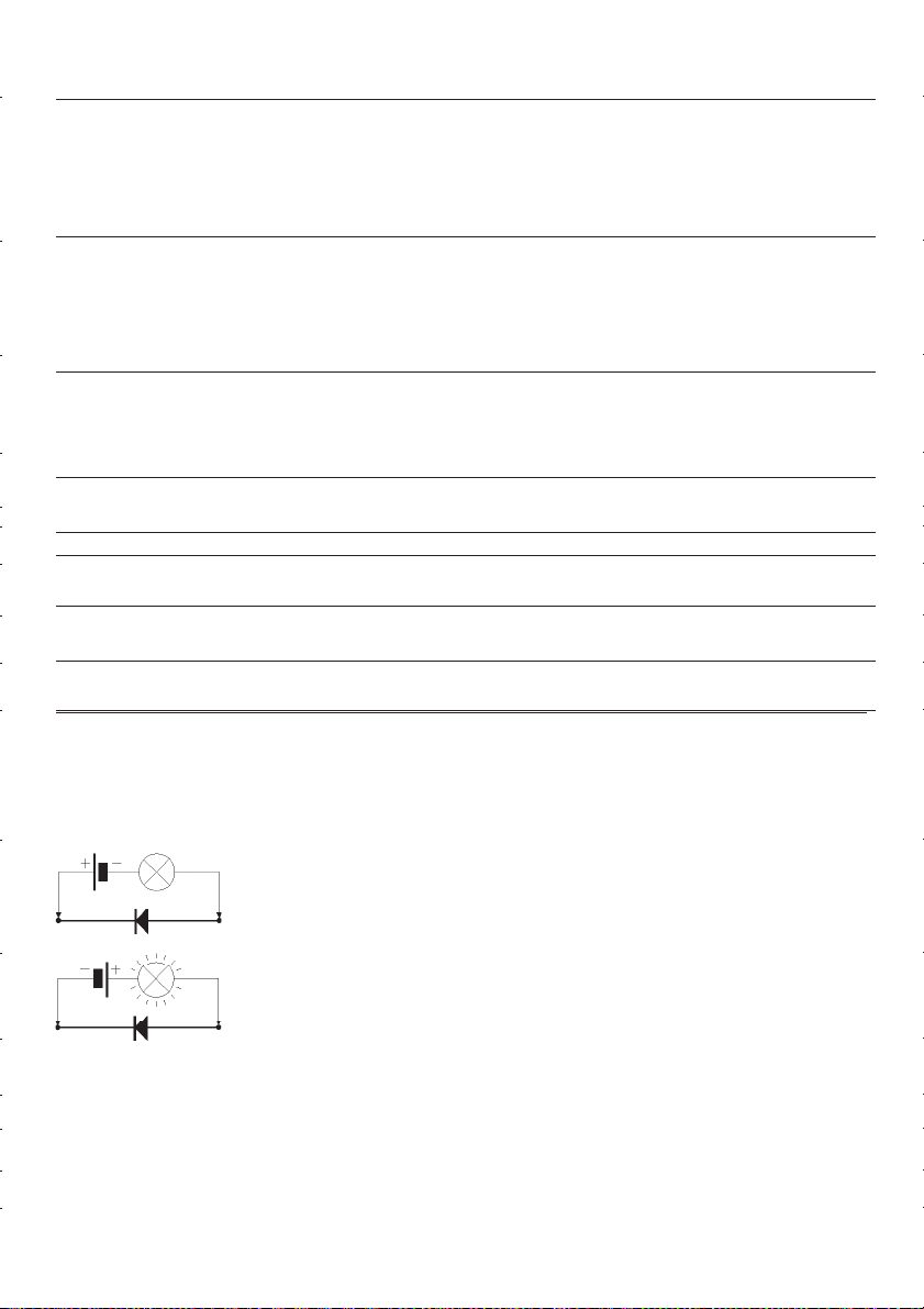
FALLA CAUSA SOLUCIÓN
Falta tensión en vacío. 1) Mando de funcionamiento en posición incorrecta. 1) Colocar el mando en la posición justa.
2) Máquina desmagnetizada. 2) Aplicar a los terminales de salida durante 1segundo
una tensión continua de entre 6-12 V.
3) Velocidad reducida. 3) Comprobar las RPM del motor yllevarlas a su valor nominal .
4) Diodos rotatorios defectuosos. 4) Comprobar ysustituir.
5) Condensador defectuoso. 5) Comprobar ysustituir.
6) Avería en los bobinados. 6) Comprobar las resistencias de los bobinados, como se indica
en la tabla.
Tensión en vacio baja. 1) Mando de corriente en posición incorrecta. 1) Colocar el mando en la posición justa.
Corriente de soldadura
baja. 2) Enchufe del cable en la gama incorrecta. 2) Poner el enchufe en la posición justa.
3) Velocidad demasiado baja. 3) Controlar la velocidad yajustarla.
4) Diodos rotatorios defectuosos. 4) Comprobar ysustituir.
5) Condensador de valor incorrecto. 5) Comprobar ysustituir.
6) Avería en los bobinados. 6) Comprobar las resistencias de los bobinados, como se indica
en la tabla.
Tensión en vacio
demasiado alta. 1) Mando de corriente en posición incorrecta. 1) Colocar el mando en la posición justa.
Corriente de soldadura 2) Enchufe del cable en la gama incorrecta. 2) Poner el enchufe en la posición justa.
demasiado alta. 3) Velocidad del motor demasiado alta. 3) Comprobar las RPM yregular.
4) Condensador de valor incorrecto. 4) Comprobar ysustituir.
5) Rotor defectuoso. 5) Sustituir el rotor.
Tensión correcta en vacío, 1) Posible sobrecarga. 1) Comprobar la corriente de carga.
demasiado baja en carga. 2) El motor decelera. 2) Comprobar el dimensionamiento del motor.
3) Diodos rotatorios defectuosos. 3) Comprobar ysustituir.
Soldadura defectuosa 1) Avería en la impedancia 1) Controlar la resistencia según la tabla ysustituir
Tensión inestable. 1) Contactos inciertos. 1) Controlar las conexiones.
Corriente de soldadura
inestable. 2) Irregularidad de rotación. 2) Verificar la uniformidad de rotación.
Sobrecalentamiento de la 1) Orificios de ventilación. 1) Desmontar ylimpiar las envolturas de aspiración y
máquina. parcialmente obstruidos. expulsión aire.
2) Posible sobrecarga. 2) Comprobar la corriente de carga.
Ruido en la máquina. 1) Cojinetes defectuosos. 1) Comprobar ysustituir.
2) Acoplamiento defectuoso. 2) Comprobar yarreglar.
Verifica dei diodi.
Con un ohmmetro controllare ogni singolo diodo che dovrà indicare continuità in un solo senso.
Oppure con una pila e una lampadina invertendo la polarità della pila la lampadina si deve accendere in un solo senso
come da figura.
Checking the diodes.
Use an ohmmeter to checkeach individual diode. Diodes must showcontinuityin one direction only.
This checkcan also be done using a batteryand a light bulb. When inverting batterypolarity, the light bulb must turn on and
off, in one direction only, as shown in the figure below.
Contrôle des diodes.
A l’aide d’un ohmmètre, contrôler les diodes une à une. Chacune d’elle devra indiquer continuitéen sens unique.
Ce test peut être réaliséavec une pile et une ampoule. En inversant les pôles de la pile, l’ampoule doit s’allumer dans le
seul sens indiquésur la figure.
Überprüfung des Gleichrichters (Dioden).
Die Dioden werden mit einem Widerstandsmessgerät (Ohmmeter) geprüft.
Die Dioden müssen in einer Richtung sperren und in der anderen durchlassen. Die Messung kann auch mit einer Glühlampe
und einer Hilfsspannüng (Batterie) durchgeführt werden. Die Lampe muss in einer Stromrichtung aufleuchten und in der
anderen dunkel bleiben (siehe Figur).
Verificaciòn de los diodos.
Con un ohmniómetro comprobar cada diodo que deberáindicar continuidad en un sólo sentido. O bien, con una pila yuna bom-
billa, invirtiendo la polaridad de la pila, la bombilla tiene que encenderse solo en un sentido, tal como se indica en la figura.
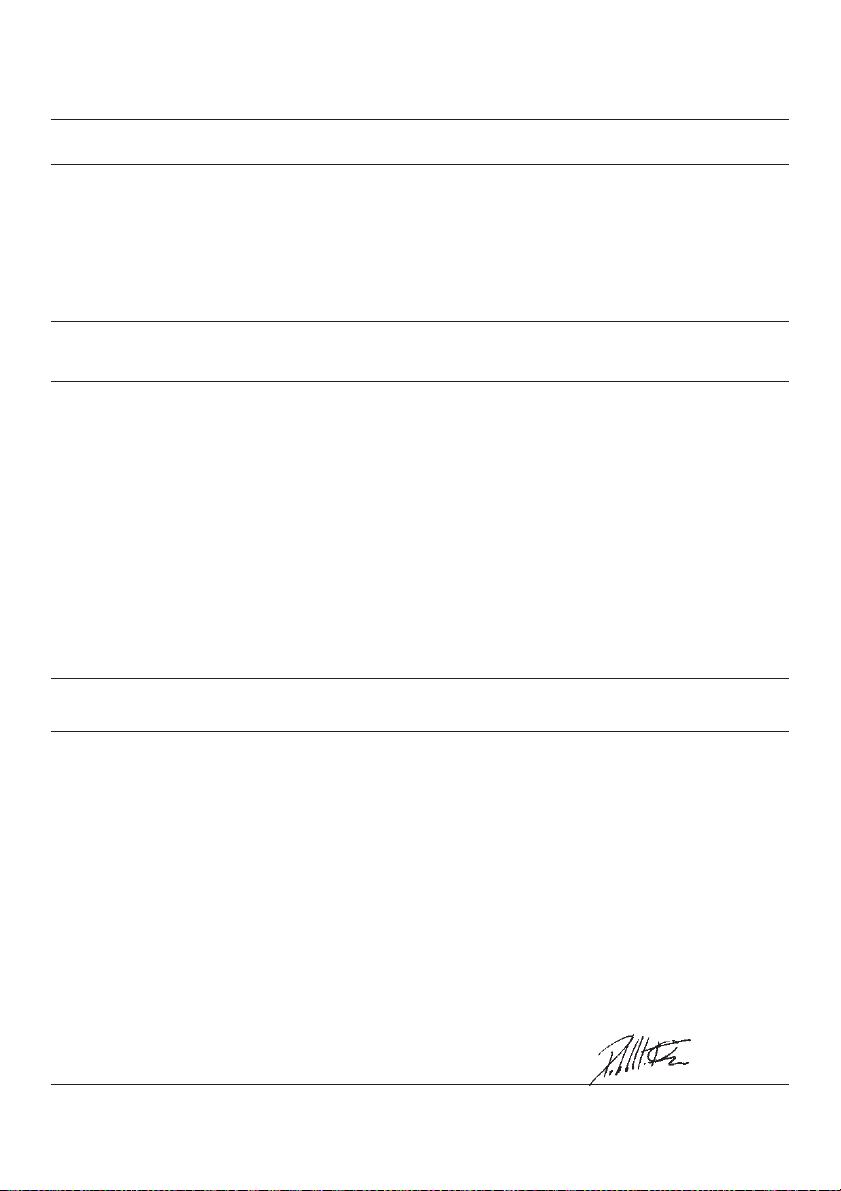
DICHIARAZIONE DI
CONFORMITA’
La società
dichiara sotto la propria
responsabilità che le sal-
datrici
serie EW-AC
sono costruite e collaudate
in accordo alle norme di
seguito indicate:
e risultano conformi:
1) ai requisiti generali di
sicurezza stabiliti dalla Di-
rettiva Bassa Tensione del
19 Febbraio 1973 (73/23
CEE), recepita in Italia con
la legge n°791 del 18 Otto-
bre 1977.
2) alla Direttiva 89/336 CEE
(mod. dalla 93/68CEE)
riguardante il ravvicinamento
delle legislazioni degli stati
membri in materia di compa-
tibilità elettromagnetica.
La verifica di compatibilità è
stata condotta in base alle
seguenti norme:
Le saldatrici oggetto del-
la presente dichiarazione
sono da intendersi come
componenti; pertanto vige il
divieto di messa in servizio
prima che le macchine in
cui saranno incorporati siano
dichiarate conformi alle diret-
tive riguardanti la sicurezza
(98/37/CE) e la compatibilità
elettromagnetica.
DÉCLARATION DE
CONFORMITÉ
La société
déclare sous sa propre
responsabilitéque les sou-
deuses
série EW-AC
sont construites et testées
selon les normes énumérées
ci-après
et sont conformes:
1) auxconditions générales
de sécuritéétablies par la
Directive Basse Tension du
19 Février 1973(72/23CEE)
approuvée en Italie par la loi
n°791 du 18 Octobre 1977.
2) à la Directive 89/336
CEE (modif. de la 93/68
CEE) concernant l’harmo-
nisation des états membres
en matière de compatibilité
électromagnétique.
La vérification de la com-
patibilitéa étéeffectuée
sur la base des normes
suivantes:
Les soudeuses objet de la
présente déclaration doivent
être considérées comme des
composants et sont donc
soumises à l’interdiction de
mise en service avant que
les machines auxquelles
elles seront incorporées
soient déclarées conformes
auxdirectives concernant
la sécurité(98/37/CE) et
la compatibilitéélectroma-
gnétique.
Cod 0900218 - 07/04
KONFORMI-
TÄTSRKLÄRUNG
Die Firma
erklärt in eigener Veran-
twortung, daßdie Schweiß-
maschinen
serie EW-AC
in Übereinstimmung mit den
nachstehend angegebenen
Normen konstruiert und ab-
genommen wurden:
und den folgenden Bestim-
mungen entsprechen:
1) den allgemeinen Sicher-
heitsanforderungen der
Direktive zur Niedrig-span-
nung vom 19. Februar 1973
(73/23EWG), die in Italien
mit Gesetz Nr. 791 vom 18.
Oktober 1977 angenommen
wurde.
2) der Direktive 89/336 EWG
(modifiziert durch 93/68
EWG) bezüglich der An-
näherung der Gesetzgebung
der Mitglieds-staaten auf
dem Gebiet der elektroma-
gnetischen Kompatibilität.
Die Überprüfung der Kom-
patibilität wurde gemäß den
folgenden Normen durch-
geführt:
Die Schweißmaschinen,
die Gegenstand der vorlie-
genden Erklärung sind, ver-
stehen sich als Komponen-
ten. Es ist daher verboten,
sie in Betrieb zu nehmen,
bevor die Maschinen, in
die sie eingebaut werden,
nicht ihrerseits als mit den
Direktiven zur Sicherheit
(98/37/CE) und zur elektro-
magnetischen Kompatibilität
übereinstimmend erklärt
wurden.
DECLARATION OF
CONFORMITY
The company
declares under its own re-
sponsibilitythat the welding
machines
series EW-AC
are made and tested in com-
pliance with the standards
listed below:
and theycomply:
1) with the general safety
requirements established
bythe LowVoltage Direc-
tive of 19 February1973
(73/23EEC), assimilated
in Italywith lawn°791 of 18
October 1977.
2) with Directive 89/336
EEC (mod. by93/68EEC)
concerning the reconcili-
ation of the legislation of
member countries on the
subject of electromagnetic
compatibility.
Compatibilitywas checked
according to the following
standards:
The welding machines to
which this declaration refers
are to be understood as
components; it is therefore
forbidden to put them into
operation before the ma-
chines in which theyare
to be incorporated have
been declared as conforming
with the directives on safety
(98/37/CE) and for electro-
magnetic compatibility.
Cereda di Cornedo, li 07/04
La SINCRO si riserva di apportare modifiche senza preavviso.
The manufacturer reserves the right to modifyfeatures without notice.
Les valeurs peuvent subir des variations sans préavis.
Die Werte können ohne Vorankündigung Änderungen unterzogen werden.
La Sincro se reserva el derecho de aportar las modificaciones sin preaviso.
DECLARACION DE
CONFORMIDAD
La sociedad
declara bajo su total re-
sponsabilidad que las sol-
dadoras
serie EW-AC
están fabricadas ycompro-
badas en el cumpli-miento
de las normas que aparecen
a continuación:
yen conformidad a:
1) los requisitos generales
de seguridad establecidos
en la Directiva de Tensión
Baja del 19 de febrero de
1973(73/23CEE), recogida
en Italia con la leyn°791 del
18 de octubre de 1977.
2) la Directiva 89/336 CEE
(mod. de la 93/68CEE),
concerniente la correspon-
dencia de las legislaciones
de los estados miembros
en materia de compatibilidad
electromagnética.
La verificación de compa-
tibilidad se ha llevado a cabo
en base a las siguientes
normas:
Las soldadoras objeto de
la presente declaración, se
entienden como componen-
tes, por tanto estáprohibida
su puesta en servicio antes
de que las máquinas a las
que serán acopladas sean
declaradas conformes a
las directivas concernientes
la seguridad (98/37/CE) y
compatibilidad electroma-
gnética.
Sincro s.r.l.
L’amministratore delegato
The Managing Director
L’Administrateur DéléguéDele-
gierter des Verwaltungsrats
El Administrador Delegado
Flavio Pistollato
SINCRO S.R.L.
- Via Tezze, 3- 36073Cereda di Cornedo Vicentino Vicenza - Italyph. +39 0445450500 - fax+39 0445446222
e-mail :sales.sincro@sogagroup.com ; e-mail :service.sincro@sogagroup.com
web :www.sogagroup.com
SINCRO S.R.L.
Via Tezze,336073Cereda di Cornedo Vicentino - Vicenza ITALY
CEI EN 60034-1(IEC 34.1, 34.5- CEI 2-3- NF 51.100 - VDE 0530 - BS 4999-5000)
CEI EN 60204-1(CEI 44-5)
EN 60974-1(IEC974-1)
EN 50199
EN 61000-6-2
EN 61000-6-3
This manual suits for next models
6
Table of contents
Other Soga Welding System manuals


 Operator's manual")


