Solid Technologies Alliance eROU User manual

Confidential & Proprietary 1/19
Alliance_eROU
User Manual
Document Reference:
Version: V1.0
Document Status: Release 1
Issue Date: March 10, 2020
Author: Yang-Su Kim
Department: R&D Division Team 2
Authorizing Manager: hyun-suk Chae
Confidential & Proprietary 2/19
REVISION HISTORY
Version
Issue Date
No. of
Pages
Initials
Details of Revision Changes
V 1.0
March 09, 2020
Original
Technical Support
SOLiD serial numbers must be available to authorize technical support and/or to establish a return
authorization for defective units. The serial numbers are located on the back of the unit, as well as on the
box in which they were delivered. Additional support information may be obtained by accessing the SOLiD
This manual is produced by Global Business Division Business Team Printed in Korea.

Confidential & Proprietary 3/19
Contents
Section1 Safety & Certification Notice .......................................................................4
Section2 System configuration and Functions...........................................................10
2.1 eROU(edge Remote Optic Unit) .......................................................................10
2.1.1 Specifications of eROU..............................................................................11
2.1.2 Port on eROU...........................................................................................12
2.1.2.1 Functions.................................................................................................12
Section3 System Installation ...................................................................................14
3.1 eROU Installation ...........................................................................................14
3.1.1 eROU Enclosure installation .......................................................................14
3.1.2 eROU(Internal Antenna) Mount Installation_ Case .1 ....................................16
3.1.3 eROU(Internal Antenna) Mount Installation_ Case .2 ....................................16
3.1.4 eROU(Internal Antenna) Mount Installation_ Case .3 ....................................17
3.1.5 eROU(External Antenna) Mount Installation.................................................17
3.1.6 Installation Cable Gland.............................................................................18
3.1.7 Power cabling...........................................................................................19
3.1.8 Ground cabling.........................................................................................19

Confidential & Proprietary 4/19
Section1
Safety & Certification Notice

Confidential & Proprietary 5/19
“Only qualified personnel should handle the DAS equipment. Any person involved in
installation or service of the DAS should understand and follow these safety guidelines.”
- Obey all general and regional installation and safety regulations relating to work on high voltage
installations, as well as regulations covering correct use of tools and personal protective equipment.
- The power supply unit in repeaters contains dangerous voltage level, which can cause electric shock.
Switch the mains off prior to any work in such a repeater. Any local regulations are to be followed when
servicing repeaters.
- eROU equipment is exclusive to the indoor.
- Use this unit only for the purpose specified by the manufacturer. Do not carry out any modifications or
fit any spare parts which are not sold or recommended by the manufacturer. This could cause fires,
electric shock or other injuries.
- Any DAS system or Fiber BDA will generate radio (RF) signals and continuously emit RF energy. Avoid
prolonged exposure to the antennas. SOLiD recommends maintaining a 500 cm minimum clearance
from the antenna while the system is operating.
- Do not operate this unit on or close to flammable materials, as the unit may reach high temperatures
due to power dissipation.
- Do not use any solvents, chemicals, or cleaning solutions containing alcohol, ammonia, or abrasives on
the DAS equipment. Alcohol may be used to clean fiber optic cabling ends and connectors.
- To prevent electrical shock, switch the main power supply off prior to working with the DAS System or
Fiber BDA. Never install or use electrical equipment in a wet location or during a lightning storm.
- Do not look into the ends of any optical fiber or directly into the optical transceiver of any digital unit.
Use an optical spectrum analyzer to verify active fibers. Place a protective cap over any radiating
transceiver or optical fiber connector to avoid the potential of radiation exposure.
- Allow sufficient fiber length to permit routing without severe bends.
- For pluggable equipment, make sure to install the socket outlet near the equipment so that it is easily
accessible.
- A readily accessible disconnect device shall be incorporated external to the equipment.
- This power of this system shall be supplied through wiring installed in a normal building.
If powered directly from the mains distribution system, it shall be used additional protection, such as

Confidential & Proprietary 6/19
overvoltage protection device
- Only 50 ohm rated antennas, cables and passive equipment shall be used with this remote. Any
equipment attached to this device not meeting this standard may cause degradation and unwanted
signals in the bi-directional system. All components connected to this device must operate in the
frequency range of this device.
- Only 50 ohm rated antennas, cables and passive components operating from 150 - 3 GHz shall be used
with this device.
- The head end unit must always be connected to the Base Station using a direct cabled connection. This
system has not been approved for use with a wireless connection via server antenna to the base station.
- Access can only be gained by SERVICE PERSONS or by USERS who have been instructed about the
reasons for the restrictions applied to the location and about any precautions that shall be taken; and
- Access is through the use of a TOOL or lock and key, or other means of security, and is on trolled by the
authority responsible for the location.
- Notice! Be careful not to touch the Heat-sink part due to high temperature.
- FCC Signal booster warning label message should include
- Certification
FCC: This equipment complies with the applicable sections of Title 47 CFR Parts 15,22,24,27 and
90(Class B)

Confidential & Proprietary 7/19
- Use of unauthorized antennas, cables, and/or coupling devices not conforming with ERP/EIRP
and/or indoor‐only restrictions is prohibited.
- Home/ personal use are prohibited.
UL/CUL: This equipment complies with UL and CUL 1950-1 Standard for safety for information
technology equipment,including electrical business equipment
FDA/CDRH: This equipment uses a Class 1 LASER according to FDA/CDRH Rules.This product
conforms to all applicable standards of 21 CFR Chapter 1, Subchaper J, Part 1040
- IC Booster warning label message should include
WARNING: This is NOT a CONSUMER device. It is designed for installation by an
installer approved by an ISED licensee. You MUST have an ISED LICENCE or the
express consent of an ISED licensee to operate this device.
FCC Part 15.105 statement
This equipment has been tested and found to comply with the limits for a Class A digital device,
pursuant to part 15 of the FCC Rules. These limits are designed to provide reasonable protection
against harmful interference when the equipment is operated in a commercial environment. This
equipment generates, uses, and can radiate radio frequency energy and, if not installed and used
in accordance with the instruction manual, may cause harmful interference to radio
communications. Operation of this equipment in a residential area is likely to cause harmful
interference in which case the user will be required to correct the interference at his own
expense.
FCC Part 15.21 statement
Any changes or modifications not expressly approved by the party responsible for compliance
could void the user's authority to operate this equipment.
RF Exposure Statement
The antenna(s) must be installed such that a minimum separation distance of at least 50 cm is
maintained between the radiator (antenna) and all persons at all times. This device must not be
co-located or operating in conjunction with any other antenna or transmitter.
RSS-GEN, Sec. 7.1.2 –(transmitters)
Under Industry Canada regulations, this radio transmitter may only operate using an antenna

Confidential & Proprietary 8/19
of a type and maximum (or lesser) gain approved for the transmitter by Industry Canada. To
reduce potential radio interference to other users, the antenna type and its gain should be so
chosen that the equivalent isotropically radiated power (e.i.r.p.) is not more than that
necessary for successful communication.
Conformément à la réglementation d’Industrie Canada, le présent émetteur radio peut
fonctionneravec une antenne d’un type et d’un gain maximal (ou inférieur) approuvé pour
l’émetteur par Industrie Canada. Dans le but de réduire les risques de brouillage radioélectrique
à l’intention desautres utilisateurs, il faut choisir le type d’antenne et son gain de sorte que la
puissance isotroperayonnée quivalente (p.i.r.e.) ne dépassepas l’intensité nécessaire à
l’établissement d’une communication satisfaisante.
RSS-GEN, Sec. 7.1.2 –(detachable antennas)
This radio transmitter (identify the device by certification number, or model number if
Category II)has been approved by Industry Canada to operate with the antenna types listed
below with the maximum permissible gain and required antenna impedance for each antenna
type indicated. Antenna types not included in this list, having a gain greater than the maximum
gain indicated for that type, are strictly prohibited for use with this device.
Le présent émetteur radio (identifier le dispositif par son numéro de certification ou son
numéro de modèle s’il fait partie du matériel de catégorie I) a été approuvé par Industrie
Canada pour fonctionner avec les types d’antenne énumérés ci-dessous et ayant un gain
admissible maximal et l’impédance requise pour chaque type d’antenne. Les types d’antenne
non inclus dans cette liste,ou dont le gain est supérieur au gain maximal indiqué, sont
strictement interdits pour l’exploitation de l’émetteur.
RF Radiation Exposure
This equipment complies with RF radiation exposure limits set forth for an uncontrolled
environment. This equipment should be installed and operated with a minimum distance of 50
cm between the radiator and your body. This transmitter must not be co-located or operating
in conjunction with any other antenna or transmitter. RF exposure will be addressed at time of
installation and the use of higher gain antennas may require larger separation distances.
RSS-102 RF Exposure
L’antenne (ou les antennes) doit être installée de façon à maintenir à tout instant une distance

Confidential & Proprietary 9/19
minimum de au moins 50 cm entre la source de radiation (l’antenne) et toute personne
physique. Cet appareil ne doit pas être installé ou utilisé en conjonction avec une autre antenne
ou émetteur.
Confidential & Proprietary 10/19
Section2
System configuration and Functions
2.1 eROU(edge Remote Optic Unit)
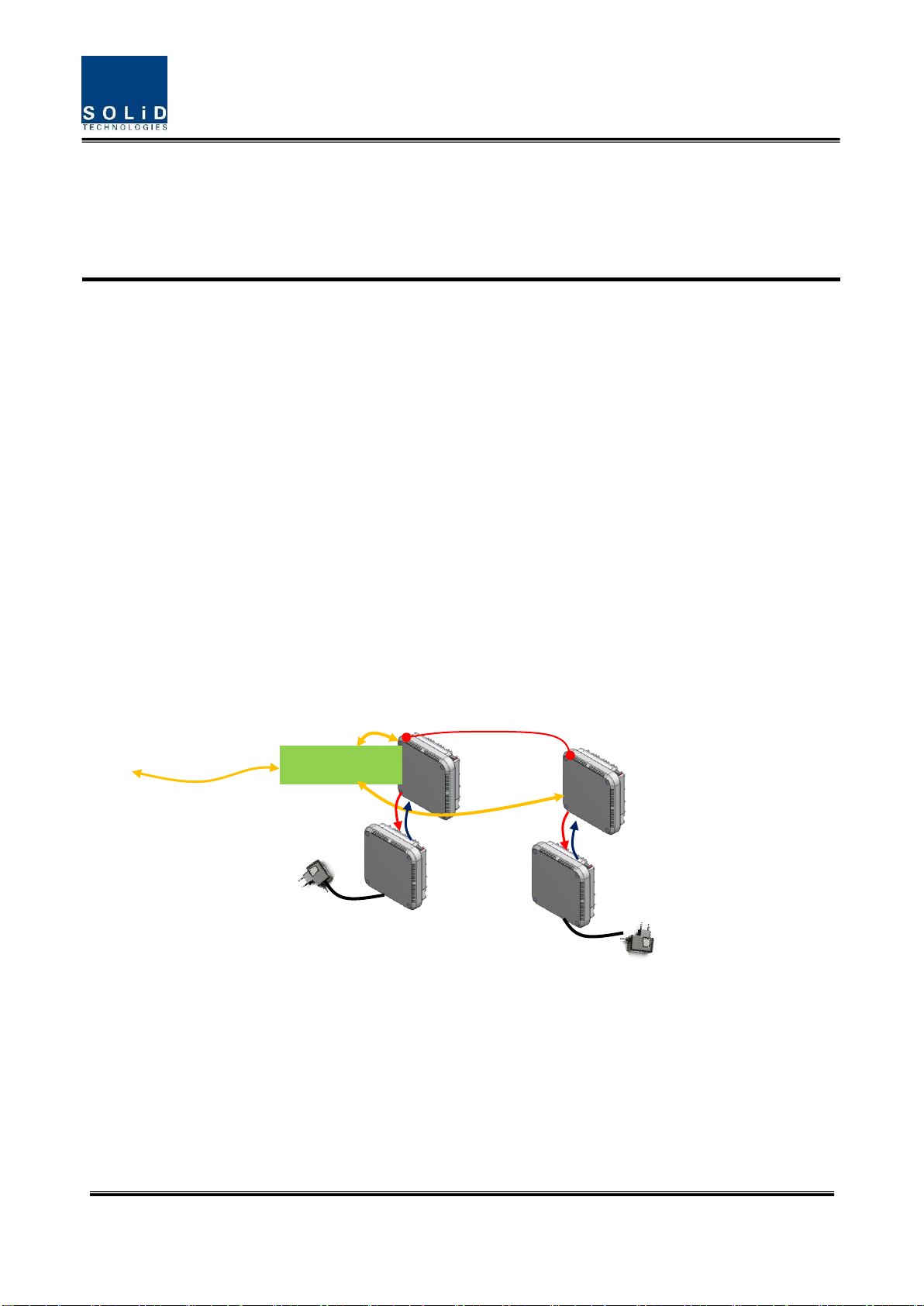
eROU receives TX optical signals from eHUB and converts them into RF signals. The converted RF signal is
radiated to the antenna port via the AMP and Multiplexer.
When receiving RX signals through the antenna port, this unit filters out-of-band signals in a
corresponding Multiplexer and sends the results to OPTIC to make electronic-optical conversion of them.
After converted, the signals are sent to a upper device of eHUB.
The eROU supports up to 4 bands.
In addition, if band extension is required, another eROU can be added up to three using optical splitters
and RF ports. However, the band expansion equipment will be developed in the future.
And eROU is divided into an Internal product with an antenna and an External product without an antenna.
Figure 1. eROU Configuration Diagram
CASCADE_KIT
eROU
cROU
aROU
aROU
External PSU
External PSU
Confidential & Proprietary 11/19
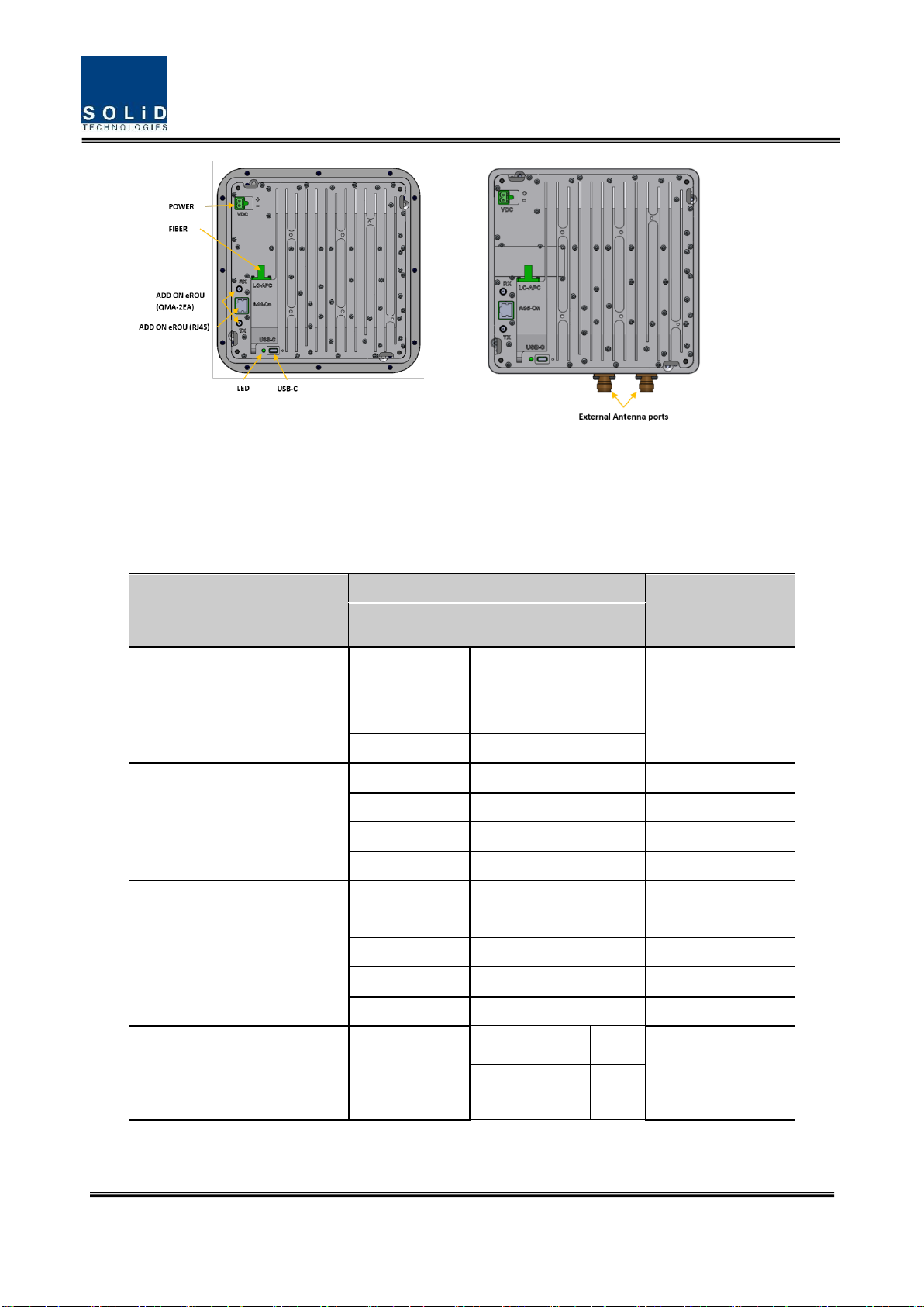
<Integrated Antenna> <External Antenna>
Figure 2. eROU outer Look
2.1.1Specifications of eROU
Item
Spec.
Remark
eROU
The rated mean output Power
per band
700LTE_FN
+19dBm
2500_100TDD
1900P
+23dBm
AWS13
+23dBm
The nominal downlink
bandwidth
700LTE_FN
39MHz
2500_100TDD
194MHz
1900P
65MHz
AWS13
70MHz
The nominal uplink bandwidth
700LTE_FN
700FN B1 : 17MHz
700FN B2 : 21MHz
2500_100TDD
194MHz
1900P
65MHz
AWS13
70MHz
The nominal passband gain
Downlink
700LTE_FN
39dB
2500_100TDD
43dB

Confidential & Proprietary 12/19
1900P
43dB
AWS13
43dB
Uplink
700LTE_FN
2500_100TDD
1900P
AWS13
45dB
Input/ Output Impedance
50 ohm
Weight
2.6 kg(Internal)
Common Part
3.0 kg(External)
Power consumption
35W
Temperature range
-5°C to +50°C
Ambient Temperature
Humidity Range
5% ~ 90%
Non-condensing
Sealing (Remote Unit)
IEC/UL/CSA 62368-1
IP50
Size(mm)
220 x 220 x 90
Integrated Antenna
200 x 200 x 73
External Antenna
2.1.2 Port on eROU
2.1.2.1 Functions
<Integrated Antenna> <External Antenna>
Figure 3. The name of each port on eROU
Confidential & Proprietary 13/19
No
Port
Quantity
Remark
1
Optical Port
1EA
LC/APC
2
ANTENNA PORT(External Only)
1EA
2.2-5 type female
3
Power IN
1EA
Terminal_Block_CONN_2P(TLPS-302V-02P-G)
4
ADD ON eROU Port
2EA
QMA-type female
5
ADD ON eROU Port
1EA
RJ45
6
USB Port
1EA
USB-C Type

Confidential & Proprietary 14/19
Section3 System Installation
3.1 eROU Installation
The following table shows the required accessories and tools for installing eROU.
No
Tools
Q’ty
Specification
Remark
1
1
(+), Ø 3.0
Length is more than 20mm
For fixing
3.1.1 eROU Enclosure installation
The eROU can be mounted on a wall or ceiling.
and divided into the version of External Antena and the version of Internal Antena.
Figure 4. eROU appearance (Left : External Antenna, Right : Internal Antenna)

Confidential & Proprietary 15/19
Figure 5. Dimension used to install eROU (internal)
Figure 3. Dimension used to install eROU (internal)
Confidential & Proprietary 16/19
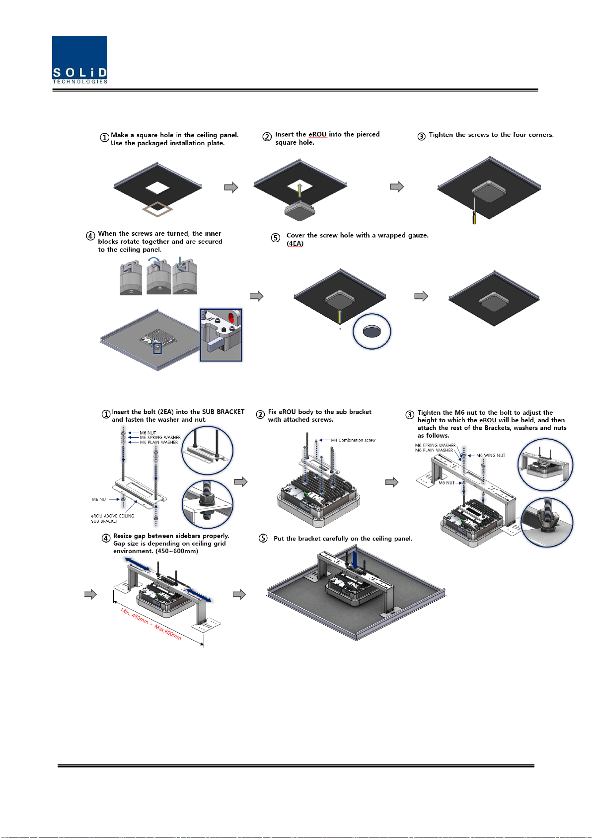
3.1.2 eROU(Internal Antenna) Mount Installation_ Case .1
3.1.3 eROU(Internal Antenna) Mount Installation_ Case .2
Confidential & Proprietary 17/19
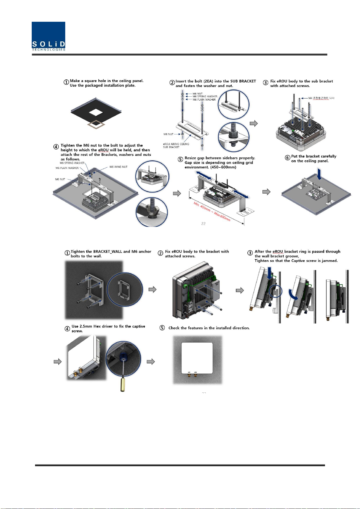
3.1.4 eROU(Internal Antenna) Mount Installation_ Case .3
3.1.5 eROU(External Antenna) Mount Installation

Confidential & Proprietary 18/19
3.1.6 Installation Cable Gland
3.1.6.1 eROU
3.1.6.2 Combine of eROU and cROU
From/To eHUB
From/To eHUB

Confidential & Proprietary 19/19
3.1.7 Power cabling
1. The eROU receives DC power from the eHub or external adapter.
2. Cable length between eHub and eROU supports up to 2.4 km.(Cable
specifications recommend AWG14.)
3. If the maximum length between the eHub and the eROU is exceeded, the use of
the External Adapter is recommended.
** Adaptor is extra purchases. Specified below shall be used only adapter.
3.1.8 Ground cabling
Not required.
Table of contents
Popular Receiver manuals by other brands


Sony
Sony HCD-DZ150K Service manual

Kenwood
Kenwood AR-404 instruction manual

Philips
Philips HTS6500 - DivX Ultra Home Theater System Service manual

Safety Technology International
Safety Technology International STI-V34104 manual

Denon
Denon AVR-X6200W owner's manual

DMP Electronics
DMP Electronics 1100DH installation guide


