- 6 -
3 4 5 6 7 8 English Spanish
0 0 0 1 0 0 4-NOTE CHIME CARILLON DE 4 NOTAS
0 0 0 1 0 1 8-NOTE CHIME CARILLON DE 8 NOTAS
0 1 1 0 1 0 ALERT ALERTA
0 1 1 1 0 1 ASSISTANCE ASISTENCIA
1 1 0 0 0 1 BARN GRANERO
1 0 1 0 1 1 BASEMENT SOTANO
0 0 1 0 0 1 BELL CAMPANA
1 1 0 1 1 1 BUTTON BOTON
0 0 1 0 1 0 BUZZER ZUMBADOR
0 1 0 0 1 1 CABINET GABINETE
0 1 1 0 0 1 CALL LLAMADA
1 1 0 1 0 1 CLOSE CERRAR
1 0 0 0 0 0 COVER CUBIERTA
0 1 1 1 1 0 CUSTOMER CLIENTE
1 0 1 1 1 0 DECK TERRAZA
0 0 0 0 0 1 DING TIMBRE (DIN)
0 0 0 0 1 0 DING-DONG DIN-DON
1 0 0 0 0 1 DOCK MUELLE
0 0 1 0 0 0 DOGS PERROS
0 0 0 0 1 1 DONG TIMBRE (DON)
0 0 1 1 1 0 DOOR PUERTA
1 0 1 0 1 0 DOWNSTAIRS ABAJO
0 1 0 0 0 1 DRIVEWAY ENTRADA
0 1 1 0 0 0 EMERGENCY EMERGENCIA
0 1 0 1 1 1 EXIT SALIDA
0 1 0 1 1 0 EXTINGUISHER EXTINTOR DE INCENDIOS
1 1 1 1 1 1 FOUR CUATRO
1 0 0 1 1 0 FREEZER CONGELADOR
0 0 1 0 1 1 FRONT FRENTE
1 0 1 1 0 1 GARAGE GAREJE
0 0 1 1 1 1 GATE ENTRADA
1 1 0 0 1 1 GUN PISTOL
1 1 0 0 0 0 HALL EL PASILLO
0 0 0 1 1 1 JINGLE BELLS CASCABEL
0 1 1 1 0 0 KEYFOB LLAVERO
1 0 1 1 0 0 KITCHEN COCINA
0 0 0 1 1 0 KNOCK LLAMADA A LA PUERTA
1 1 1 0 0 0 LIQUOR LICOR
0 1 0 0 1 0 MAILBOX BUZON DE CORREO
1 1 0 0 1 0 MEDICINE MEDICINA
0 1 0 1 0 1 MONITOR MONITOR
1 1 1 0 0 1 MOTION MOVIMIENTO
1 1 1 1 0 0 ONE UNO
1 1 0 1 0 0 OPEN ABIERTA
1 0 1 1 1 1 PATIO PATIO
1 0 0 0 1 0 POOL PISCINA
1 1 1 0 1 1 PRE-ALERT PRE-AVISO
1 1 1 0 1 0 PROTECTIVE COVER CUBIERTA PROTECTORA
0 0 1 1 0 1 REAR TRASERA
1 0 0 1 1 1 REFRIGERATOR REFRIGERADOR
0 1 0 1 0 0 SAFE CAJA FUERTE
0 1 1 1 1 1 SERVICE SERVICIO
1 0 0 0 1 1 SHED COBERTIZO
0 0 1 1 0 0 SIDE LADO
1 0 0 1 0 1 SUMP PUMP POZO DE BOMBEO
1 0 0 1 0 0 TEMPERATURE LA TERMPERATURE
0 1 1 0 1 1 THEFT ROBO
1 1 1 1 1 0 THREE TRES
1 1 0 1 1 0 TROUBLE PROBLEMAS
1 1 1 1 0 1 TWO DOS
1 0 1 0 0 1 UPSTAIRS ARRIBA
1 0 1 0 0 0 WATER LEVEL NIVEL DEL AQUA
0 1 0 0 0 0 WINDOW VENTANA
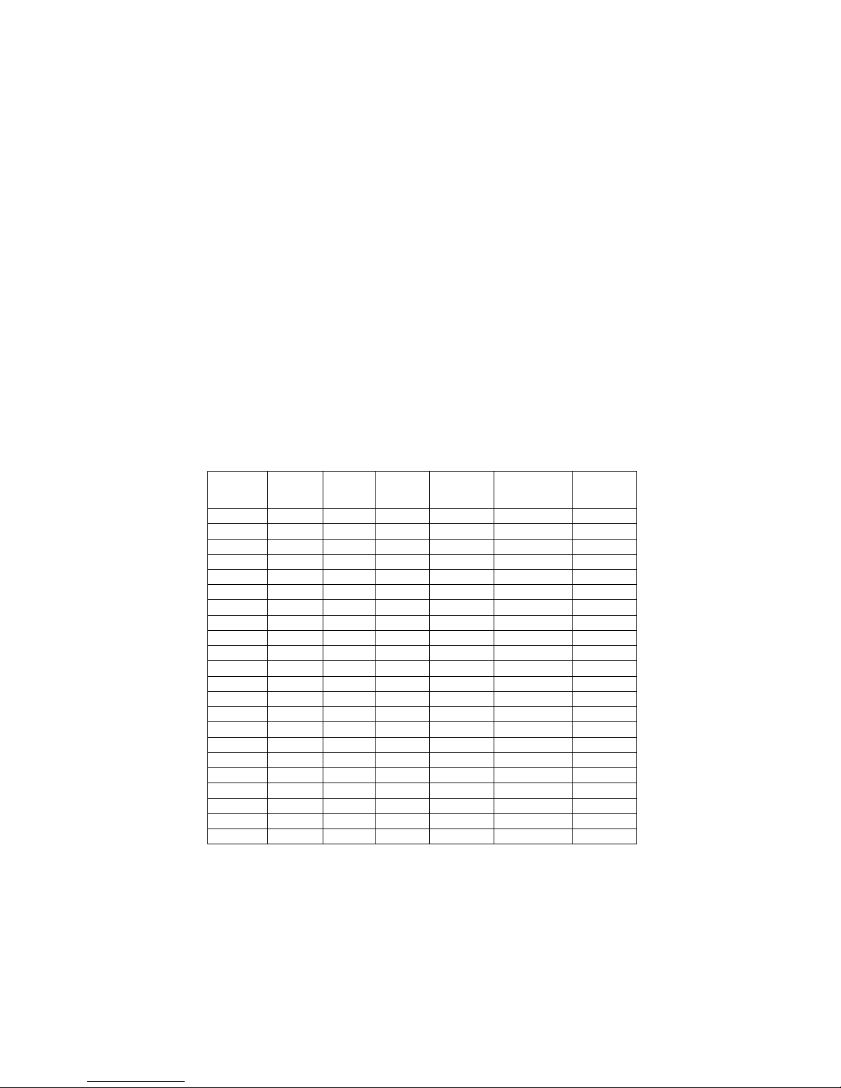
ALPHABETICAL (ENGLISH)
DIP SWITCH LANGUAGE
3 4 5 6 7 8 English Spanish
0 0 0 1 0 0 4-NOTE CHIME CARILLON DE 4 NOTAS
0 0 0 1 0 1 8-NOTE CHIME CARILLON DE 8 NOTAS
0 0 1 0 0 1 BELL CAMPANA
0 0 1 0 1 0 BUZZER ZUMBADOR
0 0 0 0 0 1 DING TIMBRE (DIN)
0 0 0 0 1 0 DING-DONG DIN-DON
0 0 1 0 0 0 DOGS PERROS
0 0 0 0 1 1 DONG TIMBRE (DON)
0 0 0 1 1 1 JINGLE BELLS CASCABEL
0 0 0 1 1 0 KNOCK LLAMADA A LA PUERTA
1 1 0 0 0 1 BARN GRANERO
1 0 1 0 1 1 BASEMENT SOTANO
1 0 1 1 1 0 DECK TERRAZA
0 1 0 0 0 1 DRIVEWAY ENTRADA
1 0 0 0 0 1 DOCK MUELLE
1 0 1 0 1 0 DOWNSTAIRS ABAJO
0 0 1 0 1 1 FRONT FRENTE
1 0 1 1 0 1 GARAGE GAREJE
1 1 0 0 0 0 HALL EL PASILLO
1 0 1 1 0 0 KITCHEN COCINA
1 0 1 1 1 1 PATIO PATIO
1 0 0 0 1 0 POOL PISCINA
0 0 1 1 0 1 REAR TRASERA
1 0 0 0 1 1 SHED COBERTIZO
0 0 1 1 0 0 SIDE LADO
1 0 1 0 0 1 UPSTAIRS ARRIBA
0 1 1 0 1 0 ALERT ALERTA
0 1 1 1 0 1 ASSISTANCE ASISTENCIA
0 1 1 0 0 1 CALL LLAMADA
1 1 0 1 0 1 CLOSE CERRAR
0 1 1 1 1 0 CUSTOMER CLIENTE
0 1 1 0 0 0 EMERGENCY EMERGENCIA
0 1 0 1 1 1 EXIT SALIDA
0 1 0 1 1 0 EXTINGUISHER EXTINTOR DE INCENDIOS
0 1 0 1 0 1 MONITOR MONITOR
1 1 1 0 0 1 MOTION MOVIMIENTO
1 1 0 1 0 0 OPEN ABIERTA
1 1 1 0 1 1 PRE-ALERT PRE-AVISO
0 1 1 1 1 1 SERVICE SERVICIO
1 0 0 1 0 0 TEMPERATURE LA TEMPERATURE
0 1 1 0 1 1 THEFT ROBO
1 1 0 1 1 0 TROUBLE PROBLEMAS
1 0 1 0 0 0 WATER LEVEL NIVEL DEL AQUA
1 1 0 1 1 1 BUTTON BOTON
0 1 0 0 1 1 CABINET GABINETE
1 0 0 0 0 0 COVER CUBIERTA
0 0 1 1 1 0 DOOR PUERTA
1 0 0 1 1 0 FREEZER CONGELADOR
0 0 1 1 1 1 GATE ENTRADA
1 1 0 0 1 1 GUN PISTOL
0 1 1 1 0 0 KEYFOB LLAVERO
1 1 1 0 0 0 LIQUOR LICOR
0 1 0 0 1 0 MAILBOX BUZON DE CORREO
1 1 0 0 1 0 MEDICINE MEDICINA
1 1 1 0 1 0 PROTECTIVE COVER CUBIERTA PROTECTORA
1 0 0 1 1 1 REFRIGERATOR REFRIGERADOR
0 1 0 1 0 0 SAFE CAJA FUERTE
1 0 0 1 0 1 SUMP PUMP POZO DE BOMBEO
0 1 0 0 0 0 WINDOW VENTANA
1 1 1 1 0 0 ONE UNO
1 1 1 1 0 1 TWO DOS
1 1 1 1 1 0 THREE TRES
1 1 1 1 1 1 FOUR CUATRO
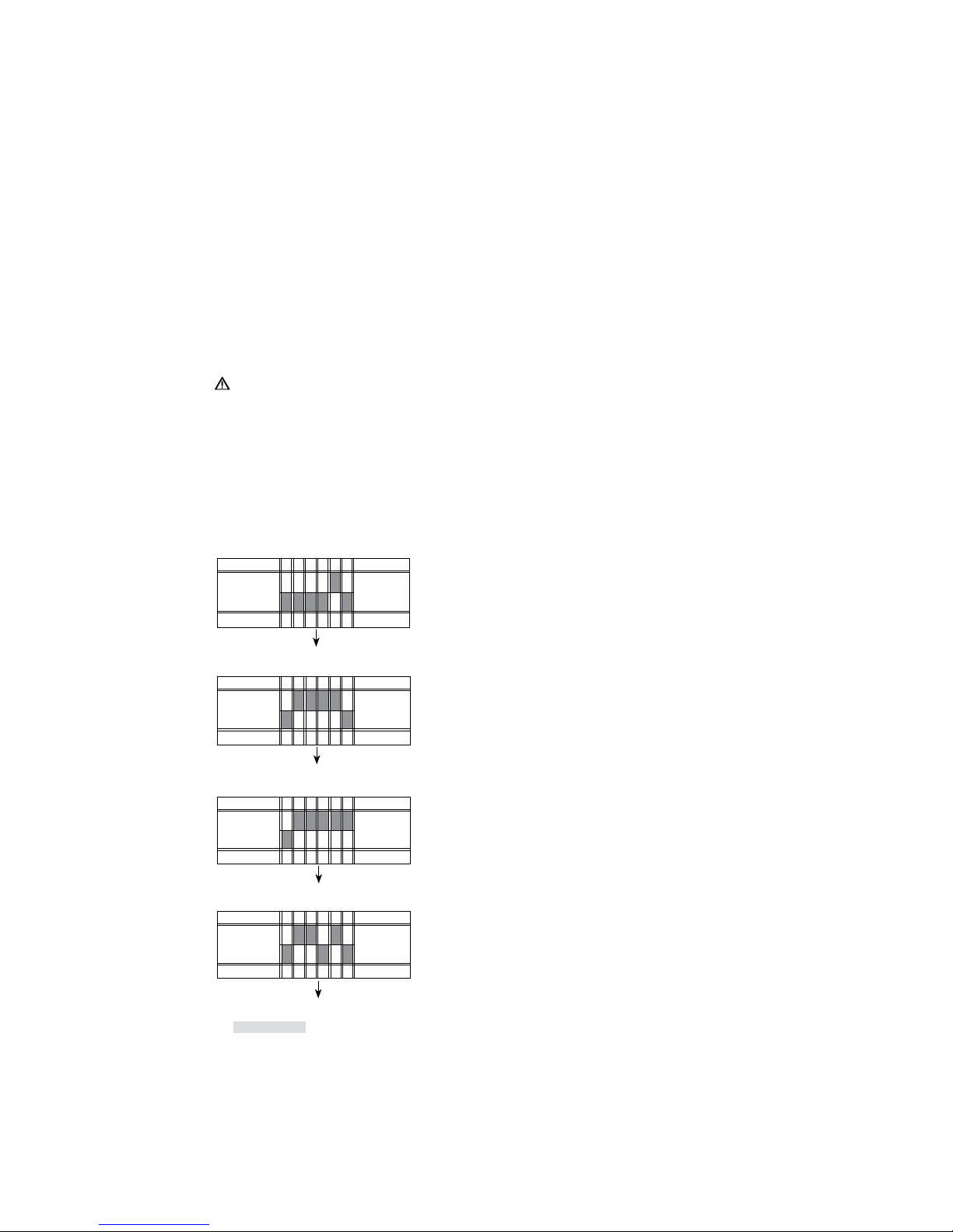
GROUPINGS
DIP SWITCH LANGUAGE
GROUP
TONES
TONOS
LOCATIONS
UBICACIONES
ALERTS
ALERTAS
OBJECTS
OBJETO
#
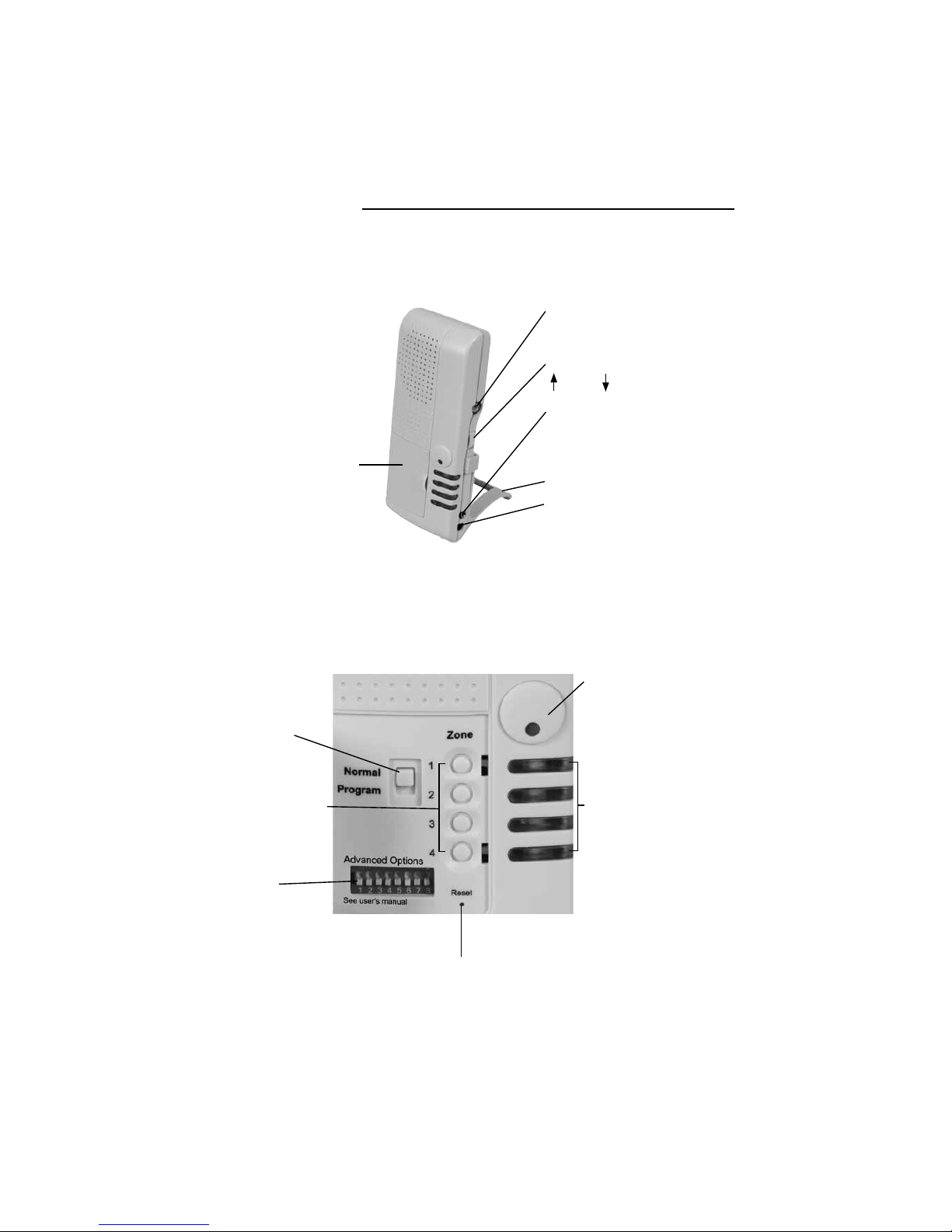
ADVANCED DIP SWITCH MESSAGE CODES
CHART 3