SON PXW-FX9V User manual
SERVICE MANUAL
1st Edition
SOLID-STATE MEMORY CAMCORDER
PXW-FX9V
PXW-FX9VK
PXW-FX9T
PXW-FX9TK
利用条件:
① 本情報はソニー製品の販売、設置、設定、使用の目的でのみご利用ください。かかる目的以外での利用を禁止します。
② 著作者の事前の書面による許可なく、本情報の全部または一部の複写、複製、転載、改変、翻訳、送信等を禁止します。
情報改訂:
本情報は、当社の裁量により、予告なく変更されることがあります。ご使用される場合、本情報が最新の情報であることを確認のうえ、
ご使用ください。
Conditions of Use:
(1) Please use this information onlyforthe purpose of sales, installation, configuration,and use of Sony products. Using this information
for anypurpose otherthan the purpose described foregoing is forbidden.
(2) Do not copy, replicate, reproduce, alter, translate, transmit, sell, lease, or distribute this information in whole or in part without the prior
written permission of the author.
Revision of Information:
This information may be changed or updated at anytime withoutany prior notice. Please confirm that this information is up-to-date before
using it.

警告
このマニュアルは,サービス専用です。
お客様が,このマニュアルに記載された設置や保守,点検,修理などを行うと感電や火災,
人身事故につながることがあります。
危険をさけるため,サービストレーニングを受けた技術者のみご使用ください。
WARNING
This manual is intended for qualified service personnel only.
To reduce the risk of electric shock, fire or injury, do not perform any servicing other than that
contained in the operating instructions unless you are qualified to do so. Refer all servicing to
qualified service personnel.
WARNUNG
Die Anleitung ist nur für qualifiziertes Fachpersonal bestimmt.
Alle Wartungsarbeiten dürfen nur von qualifiziertem Fachpersonal ausgeführt werden. Um die
Gefahr eines elektrischen Schlages, Feuergefahr und Verletzungen zu vermeiden, sind bei
Wartungsarbeiten strikt die Angaben in der Anleitung zu befolgen. Andere als die angegeben
Wartungsarbeiten dürfen nur von Personen ausgeführt werden, die eine spezielle Befähigung
dazu besitzen.
AVERTISSEMENT
Ce manual est destiné uniquement aux personnes compétentes en charge de l’entretien. Afin
de réduire les risques de décharge électrique, d’incendie ou de blessure n’effectuer que les
réparations indiquées dans le mode d’emploi à moins d’être qualifié pour en effectuer d’autres.
Pour toute réparation faire appel à une personne compétente uniquement.
CAUTION
Danger of explosion if battery is incorrectly replaced.
Replace only with the same or equivalent type rec-
ommended by the manufacturer.
When you dispose of the battery, you must obey the
law in the relative area or country.
ATTENTION
Il y a danger d’explosion s’il y a remplacement incor-
rect de la batterie. Remplacer uniquement avec
une batterie du même type ou d’un type équivalent
recommandé par le constructeur.
Lorsque vous mettez la batterie au rebut, vous devez
respecter la législation en vigueur dans le pays ou la
région où vous vous trouvez.
VORSICHT
Explosionsgefahr bei Verwendung falscher Batterien.
Batterien nur durch den vom Hersteller empfohlenen
oder einen gleichwertigen Typ ersetzen.
Wenn Sie die Batterie entsorgen, müssen Sie die
Gesetze der jeweiligen Region und des jeweiligen
Landes befolgen.
注意
指定以外の電池に交換すると,破裂する危険があり
ます。
必ず指定の電池に交換してください。
使用済みの電池は,国または地域の法令に従って
処理してください。
FÖRSIKTIGHET!
Fara för explosion vid felaktigt placerat batteri.
Byt endast mot samma eller likvärdig typ av batteri,
enligt tillverkarens rekommendationer.
När du kasserar batteriet ska du följa rådande lagar
för regionen eller landet.
PAS PÅ
Fare for eksplosion, hvis batteriet ikke udskiftes
korrekt.
Udskift kun med et batteri af samme eller tilsvarende
type, som er anbefalet af fabrikanten.
Når du bortskaffer batteriet, skal du følge
lovgivningen i det pågældende område eller land.
HUOMIO
Räjähdysvaara, jos akku vaihdetaan virheellisesti.
Vaihda vain samanlaiseen tai vastaavantyyppiseen,
valmistajan suosittelemaan akkuun.
Noudata akun hävittämisessä oman maasi tai
alueesi lakeja.
FORSIKTIG
Eksplosjonsfare hvis feil type batteri settes i.
Bytt ut kun med samme type eller tilsvarende
anbefalt av produsenten.
Kasser batteriet i henhold til gjeldende avfallsregler.

1
Table of Contents
Section 1 Service Overview..................................................................................................................................................................5
1-1. Product Comparison Table............................................................................................................................................................5
1-2. Location of Boards .......................................................................................................................................................................6
1-3. Circuit Description........................................................................................................................................................................8
1-3-1. BI-371 Board .........................................................................................................................................................................8
1-3-2. DPR-394 Board......................................................................................................................................................................8
1-3-3. DIF-278 Board.......................................................................................................................................................................8
1-3-4. JK-108 Board.........................................................................................................................................................................8
1-3-5. CR-53 Board..........................................................................................................................................................................8
1-3-6. TG-290 Board........................................................................................................................................................................8
1-3-7. SD-74 Board..........................................................................................................................................................................9
1-3-8. EC-94 Board..........................................................................................................................................................................9
1-3-9. CT-289 Board.........................................................................................................................................................................9
1-3-10. SS-108 Board.......................................................................................................................................................................9
1-3-11. IF-1377 Board......................................................................................................................................................................9
1-3-12. DD-55 Board........................................................................................................................................................................9
1-3-13. RE-349 Board ......................................................................................................................................................................9
1-3-14. DC-185 Board......................................................................................................................................................................9
1-3-15. PD-129 Board ......................................................................................................................................................................9
1-3-16. AXM-62 Board ..................................................................................................................................................................10
1-3-17. ASW-69 Board...................................................................................................................................................................10
1-3-18. HN-449 Board....................................................................................................................................................................10
1-3-19. PM-28 Board......................................................................................................................................................................10
1-3-20. VSW-82 Board...................................................................................................................................................................10
1-3-21. GCN-20 Board...................................................................................................................................................................10
1-3-22. IR-74 Board .......................................................................................................................................................................10
1-3-23. LED-54 Board....................................................................................................................................................................10
1-3-24. LE-428 Board ....................................................................................................................................................................10
1-3-25. HC-54 Board......................................................................................................................................................................11
1-3-26. KSW-72 Board...................................................................................................................................................................11
1-3-27. SW-1757 Board..................................................................................................................................................................11
1-3-28. FU-84 Board......................................................................................................................................................................11
1-3-29. SEC-59 Board....................................................................................................................................................................11
1-3-30. HP-181 Board ....................................................................................................................................................................11
1-3-31. TC-118 Board ....................................................................................................................................................................11
1-3-32. SDI-127 Board...................................................................................................................................................................11
1-3-33. VIF-78 Board.....................................................................................................................................................................11
1-3-34. VIO-38 Board ....................................................................................................................................................................11
1-3-35. PSW-110 Board..................................................................................................................................................................12
1-3-36. PR-340 Board ....................................................................................................................................................................12
1-3-37. UIF-16 Board.....................................................................................................................................................................12

2
1-3-38. UC-2 Board........................................................................................................................................................................12
1-3-39. FP-310 Board.....................................................................................................................................................................12
1-3-40. FP-311 Board.....................................................................................................................................................................12
1-3-41. FP-312 Board.....................................................................................................................................................................12
1-3-42. GP-1019 Board ..................................................................................................................................................................12
1-3-43. WF-12 Board .....................................................................................................................................................................12
1-4. Connectors and Cables................................................................................................................................................................13
1-5. Connector Input/Output Signals..................................................................................................................................................13
1-5-1. Input Signals........................................................................................................................................................................14
1-5-2. Output Signals......................................................................................................................................................................14
1-5-3. Input/Output Signals............................................................................................................................................................15
1-6. Functions of Onboard LED Indicators........................................................................................................................................23
1-6-1. DIF-278 Board.....................................................................................................................................................................23
1-6-2. DPR-394 Board....................................................................................................................................................................23
1-6-3. UIF-16 Board.......................................................................................................................................................................24
1-7. Notes on Replacing Parts and Printed Wiring Board ..................................................................................................................25
1-7-1. Power Supply during Repairs...............................................................................................................................................25
1-7-2. Precaution on Replacing the DPR-394 Board......................................................................................................................25
1-7-3. Notes for Replacing the LCD Display Device .....................................................................................................................26
1-7-4. Notes for Replacing the Front Unit Including CMOS Image Sensor...................................................................................26
1-7-5. Firmware Update .................................................................................................................................................................26
1-8. Tools and Fixtures.......................................................................................................................................................................27
1-9. Circuit Protection Parts...............................................................................................................................................................27
1-9-1. Replacing Fuses ...................................................................................................................................................................27
1-10. Electrical Adjustment................................................................................................................................................................27
1-11. Flexible Flat Cable, Flexible Board and Fine-Wire Coaxial Cable...........................................................................................28
1-11-1. Disconnecting/Connecting Flexible Flat Cable and Flexible Board...................................................................................28
1-11-2. Disconnecting/Connecting Fine-Wire Coaxial Cable.........................................................................................................29
1-11-3. Connecting/Disconnecting Coaxial Cable..........................................................................................................................33
Section 2 Replacement of Parts..........................................................................................................................................................34
2-1. Basic Knowledge........................................................................................................................................................................34
2-1-1. Tightening Torque................................................................................................................................................................34
2-1-2. Arrows on Plates and Boards ...............................................................................................................................................34
2-2. Bottom Harness Guard................................................................................................................................................................35
2-3. Outside Panel Assembly .............................................................................................................................................................40
2-3-1. ASW-69 Board.....................................................................................................................................................................42
2-3-2. AXM-62 Board ....................................................................................................................................................................43
2-3-3. VIO-38 Board ......................................................................................................................................................................45
2-3-4. JK-108 Board.......................................................................................................................................................................46
2-3-5. VIF-78 Board.......................................................................................................................................................................47
2-4. Inside Panel Assembly................................................................................................................................................................48
2-4-1. Lithium Battery....................................................................................................................................................................50

3
2-4-2. SS-108 Board.......................................................................................................................................................................51
2-4-3. TG-290 Board, SEC-59 Board.............................................................................................................................................53
2-4-4. VSW-82 Board.....................................................................................................................................................................54
2-4-5. KSW-72 Board.....................................................................................................................................................................56
2-5. Terminal Assembly .....................................................................................................................................................................59
2-6. Front Assembly...........................................................................................................................................................................61
2-7. DPR-394 Board ..........................................................................................................................................................................63
2-8. DC Fan........................................................................................................................................................................................66
2-9. Media Assembly .........................................................................................................................................................................68
2-9-1. SD-74 Board........................................................................................................................................................................69
2-9-2. EC-94 Board........................................................................................................................................................................71
2-10. Rear Assembly..........................................................................................................................................................................73
2-11. IF-1377 Board, DIF-278 Board.................................................................................................................................................75
2-12. DD-55 Board ............................................................................................................................................................................78
2-13. RE-349 Board...........................................................................................................................................................................79
2-14. Handle.......................................................................................................................................................................................80
2-14-1. Handle Upper Cabinet Assembly.......................................................................................................................................80
2-14-2. GP-1019 Board, HN-449 Board.........................................................................................................................................81
2-14-3. HC-54 Board......................................................................................................................................................................83
2-15. VF Assembly ............................................................................................................................................................................84
2-15-1. PD-129 Board ....................................................................................................................................................................84
2-15-2. Panel Module.....................................................................................................................................................................86
Section 3 Error Code ..........................................................................................................................................................................88
3-1. Error Code List ...........................................................................................................................................................................88
Section 4 Service Menu......................................................................................................................................................................91
4-1. Overview ....................................................................................................................................................................................91
4-2. Displaying the Service Menu......................................................................................................................................................91
4-3. Service Menu List.......................................................................................................................................................................91
4-4. Description of SERVICE Menu..................................................................................................................................................92
4-4-1. Auto Black Balance Menu ...................................................................................................................................................92
4-4-2. RPN Menu ...........................................................................................................................................................................92
4-4-3. Factory Reset Menu.............................................................................................................................................................92
4-4-4. Information Menu................................................................................................................................................................92
4-4-5. Version Menu.......................................................................................................................................................................92
Section 5 Spare Parts..........................................................................................................................................................................93
5-1. Note on Repair Parts...................................................................................................................................................................93
5-2. Exploded Views..........................................................................................................................................................................94
Overall-1.........................................................................................................................................................................................94
Overall-2.........................................................................................................................................................................................95
Terminal Assembly.........................................................................................................................................................................96
DC Fan ...........................................................................................................................................................................................97
DPR Board .....................................................................................................................................................................................98

4
DD Board, RE Board......................................................................................................................................................................99
Outside Panel................................................................................................................................................................................100
Inside Panel-1...............................................................................................................................................................................102
Inside Panel-2...............................................................................................................................................................................103
Inside Panel-3...............................................................................................................................................................................104
Inside Panel-4...............................................................................................................................................................................105
Front.............................................................................................................................................................................................106
Media Assembly...........................................................................................................................................................................107
Rear..............................................................................................................................................................................................108
Handle-1.......................................................................................................................................................................................109
Handle-2.......................................................................................................................................................................................110
Handle-3....................................................................................................................................................................................... 111
VF Hood.......................................................................................................................................................................................112
VF Block......................................................................................................................................................................................113
Grip-1...........................................................................................................................................................................................115
Grip-2...........................................................................................................................................................................................116
Grip-3...........................................................................................................................................................................................117
5-3. Supplied Accessories ................................................................................................................................................................119
Section 6 Diagrams...........................................................................................................................................................................120
Overall .............................................................................................................................................................................................120
Frame Wiring...................................................................................................................................................................................123
Revision History..................................................................................................................................................................................124

5
Section 1
Service Overview
1-1. Product Comparison Table
Model
PXW-FX9V
PXW-FX9VK
PXW-FX9T
PXW-FX9TK
Destination
UC, J, CN1, CEE
UC, CEE
COLOR system
NTSC/PAL (Selectable)
NTSC/PAL (Selectable)
Internal recording media
—
—
LENS
—
SELP28135G
—
SELP28135G
Projector
—
—
GPS
✓
✓
EVF
✓
✓
Wi-Fi
2.4/5.2/5.3/5.6/5.8 GHz
2.4 GHz
NFC
✓
✓
Multi interface shoe
✓
✓
Charging capacitor (for flash)
—
—

6
1-2. Location of Boards
DIF-278
GCN-20
VSW-82
EC-94
HP-181
TG-290
SEC-59
FU-84
SS-108
SW-1757
KSW-72
IF-1377
WF-12
DD-55
RE-349
DC-185
VIF-78
TC-118
JK-108
DPR-394
VIO-38
CT-289
ASW-69
AXM-62
SD-127
SD-74
PM-28
7
PSW-110
PR-340
PD-129
GP-1019
HC-54
HN-449
UIF-16
UC-2

8
1-3. Circuit Description
1-3-1. BI-371 Board
The BI-371 board contains a full-frame CMOS image sensor.
Power is supplied to this board from the DPR-394 board through the connector.
The CMOS image sensor converts an optical signal to an electrical signal, and its internal A/D converter converts the electrical signal
to a digital signal. Then this digital signal is converted to a differential serial signal, and then this serial signal is output to the
DPR-394 board.
1-3-2. DPR-394 Board
The DPR-394 board contains IC6300, IC1001, IC1001, IC2001, IC3001, IC3501, and IC6000.
Signals from the imager are input to IC6300.
IC1001 distributes image signals to IC2001 and IC6000.
IC2001 performs main-line signal processing.
IC6000 detects radio waves to control the lens.
IC3001encodes and decodes main-line signals from IC2001.
The encoded data is sent to IC6000 and the data from IC6000 is recorded in the media.
With respect to external output signals, monitor signals are sent from IC2001 to IC3501 and then to the SDI/HDMI/VIDEO OUT
driver. Then the monitor signals are output from each connector.
1-3-3. DIF-278 Board
The DIF-278 board contains an FPGA, an audio DSP, a PCIe switch, a USB HOST controller, an Ether PHY controller, and a
connector for interface with the extended interface box.
The FPGA (IC0700) relays video and audio data between IC2001 and IC6000 on the DPR-394 board, and also relays control signals
and audio data of the audio DSP (IC1000). This FPGAalso distributes clock signals for the audio circuit.
The audio DSP (IC1000) switches audio signals for each channel, adjusts volume, and performs filter processing.
The PCIe switch (IC0300) distributes the PCIe communication bus from IC 6000 on the DPR-394 board to four channels (two XQD
card slots (EC-94 board), USB-HOST controller (IC1202), and Ether PHY controller (IC1101).
All REF clock signals of the PCIe communication bus in this unit are generated in and distributed from IC0604.
The interface connector (CN1401) on the extended interface box relays the following signals.
• RAW data signal from IC2001 on the DPR-394 board, communication signals, and synchronous clock signal
• Power voltages from the extended interface box and power control signals
• USB BUSx2 signal from the USB-HOST controller (IC1202)
• Ethernet communication bus from the Ether PHY controller (IC1101)
• Audio clock signal for WRR and return data
• FPGA update signal in the extended interface box
1-3-4. JK-108 Board
The JK-108 board contains a USB/multi-connector, a REMOTE connector, and a TC/GENLOCK IN/OUT select switch.
The USB and UART signals on the USB/multi-connector are connected to IC6000 on the DPR-394 board.
The LANC signal line on the REMOTE connector is connected to IC1002 on the DD-55 board and a power voltage is also supplied.
1-3-5. CR-53 Board
The CR-53 board contains a driver IC6501 to control the variable ND filter.
Control signals of the variable ND filter are connected from IC6000 on the DPR-394 board.
Signals from IC6501 are connected to the ND unit to insert or remove the variable liquid crystal ND of the ND unit and to change the
density of the variable liquid crystal ND.
1-3-6. TG-290 Board
The TG-290 board contains an ISO/GAIN switch (for switching gain) and a WHT BAL switch (for switching white balance
memory).

9
1-3-7. SD-74 Board
The SD-74 board contains an SD/MS slot (CN001), an LED (D001) for displaying SD/MS ACCESS, a transistor (Q001), and an
ATTENTION switch (S001).
1-3-8. EC-94 Board
The EC-94 board contains XQD card slots (SLOTA: CN902, SLOT B:CN903), XQD power control devices (IC900, IC901, IC902,
IC903, IC904, Q908, Q909, Q910, and Q911), and XQDACCESS display devices (D901, D902, D903, D911, D912, D913, D924,
D925, D926, D934, D935, D936, Q900, Q901, Q902, and Q907).
The PCIe signal from IC0300 on the DIF-278 board is input to the XQD connector.
1-3-9. CT-289 Board
The CT-289 board contains a Wi-Fi module.
The Wi-Fi module sends data to and receives data from IC6000 on the DPR-394 board.
Wi-Fi radio waves are emitted from the antenna on the WF-12 board.
1-3-10. SS-108 Board
The SS-108 board contains an NFC Plug IC, a HOLD switch, a recording START/STOP button, a REC LED, and a VOLUME button
(for adjusting monitor volume).
The NFC Plug IC sends/receives data from IC6000 on the DPR-394 board through the NFC antenna.
1-3-11. IF-1377 Board
The IF-1377 board in the unit is a connector board for relay between the unit and the handle.
This board relays switch signals of the handle, GPS receiver, and power and communication lines of the MI SHOE.
1-3-12. DD-55 Board
The DD-55 board contains IC1001, IC01002, IC2001, IC3002, and IC4001.
IC3002 receives the power switch signal from the SS-108 board to control power ON/OFF.
The 5 V power voltage from the RE-349 board is converted to several voltages in IC1001 and IC1002, and then converted voltages
are supplied to ICs.
The 8 V power voltage from the RE-349 board is converted to a proper voltage in IC4001, and then the converted voltage is supplied
to the fan.
IC2001 receives the LANC signal from the REMOTE connector on the JK-108 board for control from the remote controller.
1-3-13. RE-349 Board
The RE-349 board contains IC1005 and IC2002.
IC1005 controls uninterruptible switching.
The external power voltages from the DC IN jack on the DC-185 board, battery, and the DIF-278 board are converted to 5 V and 7 V
voltages in IC2002, and then these voltages are supplied to the DD-55 board.
1-3-14. DC-185 Board
The DC-185 board contains a DC IN jack.
1-3-15. PD-129 Board
The PD-129 board is connected to the panel module and the VF cable.
Parallel video signals are output from IC3501 on the DPR-394 board and are converted to a serial signal in IC2251 on the DPR-394
board.
Panel control signals are received from IC302 on the VIO-38 board.

10
1-3-16. AXM-62 Board
The AXM-62 board contains an XLR connector and an external input ADC.
External audio input signals connected to the XLR connector are input to the ADC and are converted to digital data.
The converted digital data is input to IC0700 on the DIF-278 board.
1-3-17. ASW-69 Board
The ASW-69 board contains an INPUT switch (LINE/MIC/MIC+48V) of the XLR connector and power IC3001. IC3001 generates a
48 V voltage. When MIC+48V is selected, the 48 V is supplied to the XLR connector on the AXM-62 board.
1-3-18. HN-449 Board
The HN-449 board contains an MI SHOE ADC.
The ADC converts audio signals input from the MI SHOE to digital data and the digital data is sent to IC0700 on the DIF-278 board.
The HN-449 board also relays signals of the GPS reception unit and the REC and ZOOM keys.
1-3-19. PM-28 Board
The PM-28 board contains a power switch.
The power switch signals are input to IC3002 on the DD-55 board to control power ON/OFF.
1-3-20. VSW-82 Board
The VSW-82 board contains the following switches, buttons, and LEDs.
• ND FILTERPOSITION upper and lower buttons
• ND CLEAR display LED
• ND VARIABLE AUTO button/LED
• ISO/GAIN function button/LED
• SHUTTER (shutter) function button/LED
• WHT BAL (white balance) function button/LED
• STATUS button
• FOCUS switch
• PUSH AUTO FOCUS (one-push auto focus) button/LED
• IRIS function button
• PUSH AUTO IRIS (push auto iris) button/LED
1-3-21. GCN-20 Board
The GCN-20 board contains anASSIGN9 button and an LED.
1-3-22. IR-74 Board
The IR-74 board detects the lens mount lock status.
This status is enabled when the S5501 lever is pressed.
1-3-23. LED-54 Board
The LED-54 board contains an LED for FRONT TALLY.
This board relays the lens mount lock signal from the IR-74 board.
1-3-24. LE-428 Board
The LE-428 board contains an LED for REAR TALLY.

11
1-3-25. HC-54 Board
The HC-54 board in the handle is a connector board for relay between the unit and the handle.
This board relays switch signals of the handle, GPS receiver, and power and communication lines of the MI SHOE.
1-3-26. KSW-72 Board
The KSW-72 board contains a power LED, an inside key switch, a button battery, LEDs for ASSIGN7 and ASSIGN8, and an audio
headphone/speaker amplifier DAC (IC8402).
The power LED lights when power is turned on.
The inside key switch signals are input to theADC port of IC6000 on the DPR-394 board.
1-3-27. SW-1757 Board
The SW-1757 board contains ASSIGN 1, ASSIGN 2, and ASSIGN 3 buttons and an LED DISPLAY button.
1-3-28. FU-84 Board
The FU-84 board contains a multifunction dial.
1-3-29. SEC-59 Board
The SEC-59 board contains a WB SET (white balance set) button.
1-3-30. HP-181 Board
The HP-181 board contains a headphone jack.
Audio signals are connected to the output pins of IC8402 on the KSW-72 board.
1-3-31. TC-118 Board
The TC-118 board contains a TCIN/TCOUT (timecode input/output) connector and a GENLOCK IN (for Genlock input)/REF OUT
(sync signal output) connector.
Both input and output timecode signals are connected to IC3501 on the DPR-394 board.
The Genlock signal is isolated to H/V/F sync signals in IC5108, and then these signals are input to IC3501 on the DPR-394 board.
The Refout signal is output from IC3501 on the DPR-394 board. Its waveform is shaped in the circuit of the TC-118 board and is
then output to the external circuit.
1-3-32. SDI-127 Board
The SDI-127 board contains a BNC connector (SDI OUT 1 connector) that can output 12G-SDI signals and a BNC connector (SDI
OUT 2 connector) that can output 3G-SDI signals.
IC6004 is a 12G-SDI driver IC.
IC6003 is a 3G-SDI driver IC.
1-3-33. VIF-78 Board
The VIF-78 board contains a connector for connection to the viewfinder. This connector is connected to the PD-129 board through
the viewfinder cable.
1-3-34. VIO-38 Board
The VIO-38 board relays signals between the camera body and the outside connector.
This board contains IC302 that sends panel control signals.

12
1-3-35. PSW-110 Board
The PSW-110 board contains ZEBRA, PEAKING, andASSIGN10 buttons.
1-3-36. PR-340 Board
The PR-340 board contains a MIRROR switch (3-position slide switch) to switch ROTATE, B/T, and OFF of the viewfinder.
1-3-37. UIF-16 Board
The UIF-16 board is a grip board to control the grip using IC2002.
When this board is connected to the camera body, the LED (D2002) lights green.
The LED (D2001) also blinks orange when the CPLD firmware has been successfully updated.
1-3-38. UC-2 Board
The UC-2 board contains anASSIGN6 button.
1-3-39. FP-310 Board
The FP-310 board contains an MI SHOE connector.
1-3-40. FP-311 Board
The FP-311 board contains ASSIGN4, ASSIGN5, and Rec buttons, eight direction keys, and a photo reflector to activate the
multi-assignable dial.
1-3-41. FP-312 Board
The FP-312 board contains a photo reflector to detect the variable liquid crystal ND insertion/removal position.
1-3-42. GP-1019 Board
The GP-1019 board contains a GPS antenna and a GPS module.
This GPS module is controlled by the UART signals from IC6000 on the DPR-394 board.
1-3-43. WF-12 Board
The WF-12 board contains a Wi-Fi antenna.
13
1-4. Connectors and Cables
When connecting cables to connectors during installation or service, use connectors and cables that meet the specifications of this
unit.
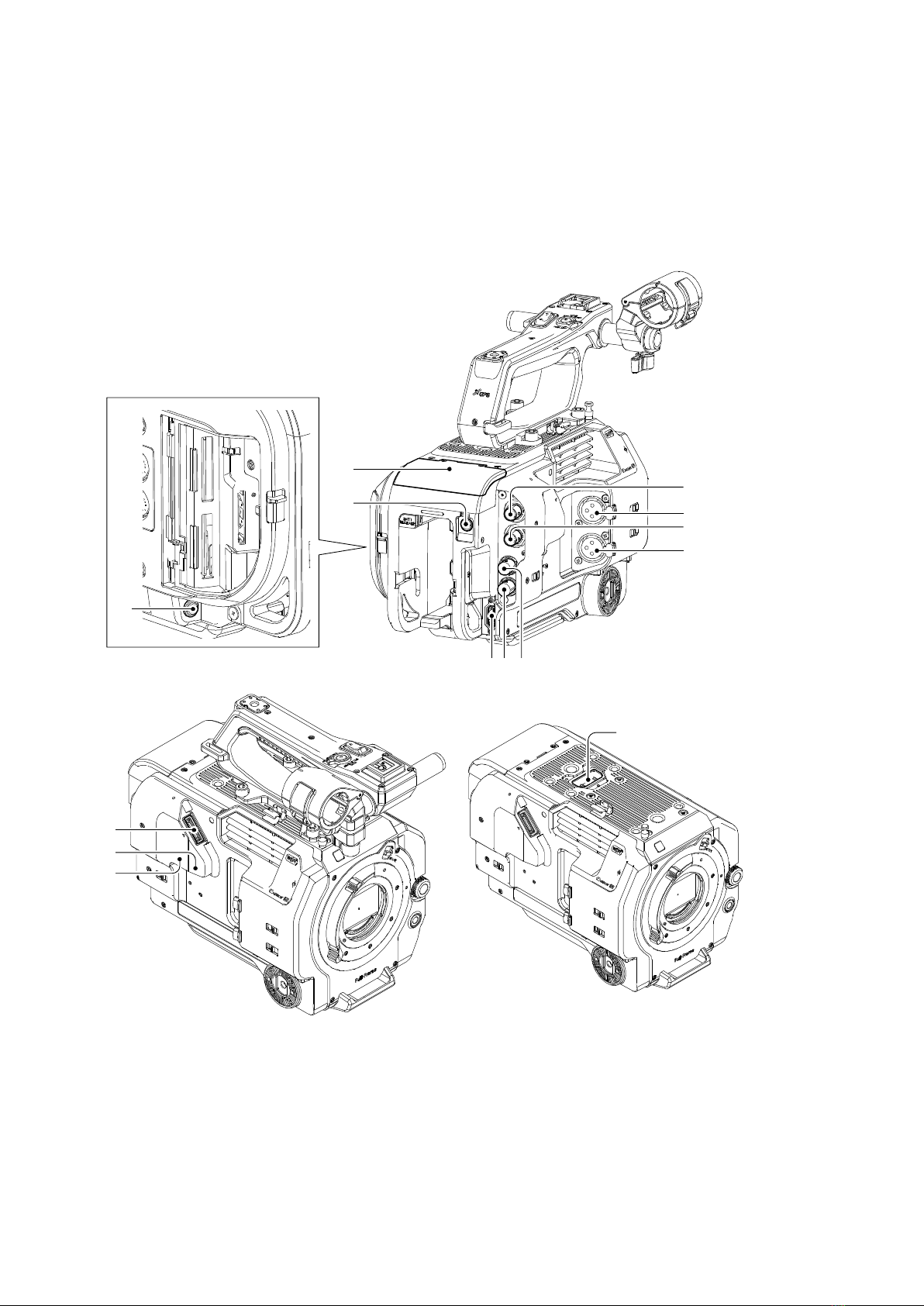
1-5. Connector Input/Output Signals
3
2
4
2
12
11
10
6
879
13
5
1
14
1-5-1. Input Signals
1. DC IN
DC jack
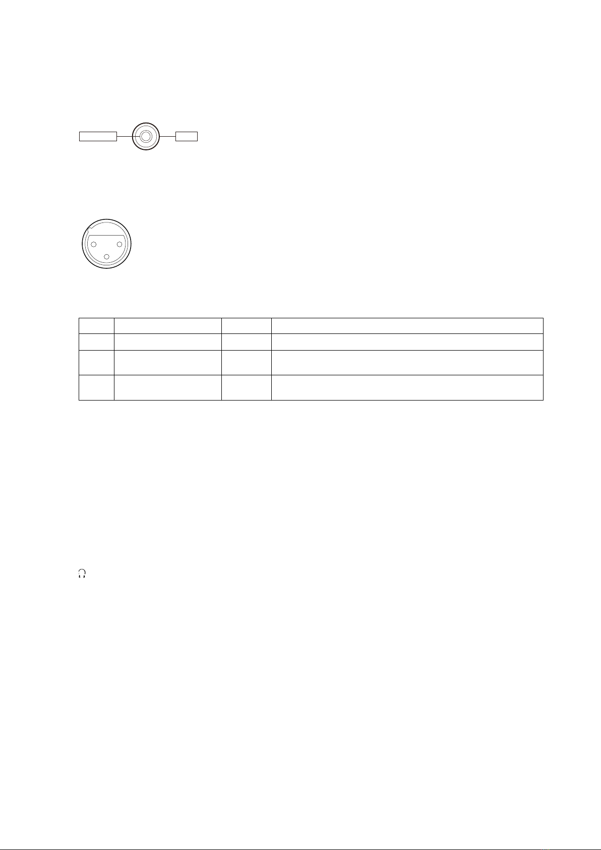
2. AUDIO INPUT 1/2
No.
Signal
I/O
Specifications
1
GND
—
GND
2
XLR HOT
IN
LINE: +4 dBu/0 dBu/-3 dBu (/EBUL)/10 k ohms
MIC: -80 dBu to -30 dBu/3 k ohms
3
XLR COLD
IN
LINE: +4 dBu/0 dBu/-3 dBu(/EBUL)/10 k ohms
MIC: -80 dBu to -30 dBu/3 k ohms
LINE/MIC/MIC+48V selectable
1-5-2. Output Signals
3. SDI OUT 1
BNC type
12G/3G/HD selectable
4. SDI OUT 2
BNC type
3G/HD selectable
5. (Headphone)
Stereo mini jack
–16 dBu (Volume: Max, reference level output 16 ohms loaded)
- External View -
GNDEXTDC
1
2
3
- External View -
(0 dBu = 0.775 V rms)
XLR 3-pin, Female

15
6. USB/MULTI
Multi/micro USB
No.
Signal
I/O
Specifications
1
USB_VBUS
IN
+
5V power (input)
2
USB D-
IN/OUT
USB Data- signal
3
USB D+
IN/OUT
USB Data+ signal
4
USB_ID
IN
OTG identification signal (not used)
5
GND
—
GND
6
D_3.3V
OUT
7
XRESET_REQ
IN
Camera power On/Off control (for debugging)
8
UART_TX
IN/OUT
UART TX for multi-connector
9
UART_RX
IN/OUT
UART RX for multi-connector
10
AD_JACK_IN
IN
AD signal for determining accessory type
11
ROUT/XAELOCK
—
Not used
12
LOUT/XSHUT
—
Not used
13
V_LINE_OUT
—
Not used
14
GND
—
GND
15
XPWR_ON
OUT
Camera power On/Off control (for debugging)
1-5-3. Input/Output Signals
7. GENLOCK IN/REF OUT
BNC type 1.0 V p-p, 75 ohms
GENLOCK IN/HD-SYNC OUT selectable
8. TC IN / OUT
BNC type
• TC IN
0.5 to 18 V p-p, 3.3 k ohms
• TC OUT
1.0 V p-p, 75 ohms
TC IN/TC OUT selectable
-External View-
1
615
5

16
9. HDMI OUT
No.
Signal
I/O
Specifications
1
TMDS DATA2+
OUT
TMDS data 2 (+) output
2
TMDS DATA2 SHIELD
—
GND for TMDS data 2
3
TMDS DATA2-
OUT
TMDS data 2 (-) output
4
TMDS DATA1+
OUT
TMDS data 1 (+) output
5
TMDS DATA1 SHIELD
—
GND for TMDS data 1
6
TMDS DATA1-
OUT
TMDS data 1 (-) output
7
TMDS DATA0+
OUT
TMDS data 0 (+) output
8
TMDS DATA0 SHIELD
—
GND for TMDS data 0
9
TMDS DATA0-
OUT
TMDS data 0 (-) output
10
TMDS CLOCK+
OUT
TMDS clock signal (+) output
11
TMDS CLOCK SHIELD
—
GND for TMDS clock
12
TMDS CLOCK
OUT
TMDS clock signal (-) output
13
CEC (N.C.)
—
—
14
RESERVED (N.C.)
—
No connection
15
SCL
OUT
Serial data clock signal output
16
SDA
IN/OUT
Serial data signal input/output
17
DDC/CEC GND
—
GND
18
+5 V POWER
OUT
+5 V dc output
19
HPD
IN
Hot plug detect signal input
10. REMOTE
2.5 mm stereo mini mini jack
- External View -
Type A
19 1
18 2

17
11. Viewfinder connector
Note
The viewfinder connection cable supplied with the unit is not connected in a 1-1 or 1-N manner.
No.
Signal
I/O
Specifications
1
GND
—
GND
2
GND
—
GND
3
GND(VF_DET2)
—
Cable connection detection signal 2 (GND)
4
CAP_TP_INT
OUT
Touch panel interrupt signal
5
+5V
OUT
+5V power
6
LVDS DATA 2+
OUT
LVDS data 2 (+) output
7
LVDS DATA2-
OUT
LVDS data 2 (-) output
8
LVDS DATA1+
OUT
LVDS data 1 (+) output
9
LVDS DATA 1-
OUT
LVDS data 1 (-) output
10
GND
—
GND
11
GND
—
GND
12
LVDS CLOCK+
OUT
LVDS clock signal (+) output
13
LVDS CLOCK-
OUT
LVDS clock signal (-) output
14
LVDS DATA 0+
OUT
LVDS data 0 (+) output
15
LVDS DATA 0-
OUT
LVDS data 0 (-) output
16
CAP_TP_XRES
IN/OUT
Reset signal from ASTRA to TP
17
STX
OUT
Data signal from VINE to LCD
18
SCK
OUT
Clock signal from VINE to LCD
19
GND
—
GND
20
GND
—
GND
21
I2C SDA
I2C data signal from ASTRA to TP
22
LVDS DATA 3+
OUT
LVDS 3 (+) output
23
LVDS DATA 3-
OUT
LVDS 3 (-) output
24
+5V
OUT
+5Vpower
25
+5V
OUT
+5Vpower
26
XLCD_TXEN(GND)
—
Connect to GND
27
GND
—
GND
28
KEY0_AD2
IN
Key switch AD ladder signal
29
GND
—
GND
30
KEY0_AD3
IN
Key switch AD ladder signal (not used)
31
GND
—
GND
32
TP_SDA
IN/OUT
Data signal from ASTRA to TP
33
GND
—
GND
34
TP_SCL
OUT
Clock signal from Astra to TP
35
GND
—
GND
Continued
120
21 40
-External View-
This manual suits for next models
3
Table of contents
Other SON Camcorder manuals


