manuals.online logo
Brands
  1. Home
  2. •
  3. Brands
  4. •
  5. Sony
  6. •
  7. Camcorder
  8. •
  9. Sony NEX-EA50CH User manual

Sony NEX-EA50CH User manual

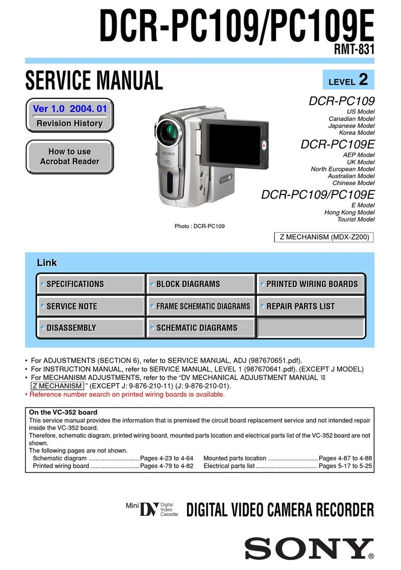
SERVICE MANUAL
Revision History
Published by Sony Techno Create Corporation
Sony Corporation
SERVICE NOTE (Check the following note before the service.)
NEX-EA50CH/EA50CK/EA50EH/EA50H/EA50JH/EA50K/EA50UH
983469913.pdf
Ver. 1.2 2013.08
INTERCHANGEABLE LENS DIGITAL HD VIDEO CAMERA RECORDER
The components identified by mark
0or dotted line with mark 0are
critical for safety.
Replace only with part number
specified.
Les composants identifiés par une
marque 0sont critiques pour la
sécurité.
Ne les remplacer que par une
pièce portant le numéro spécifié.
9-834-699-13
US Model
Canadian Model
AEP Model
E Model
Chinese Model
Japanese Model
Ver. Date History Contents S.M. Rev.
issued
1.0 2012.10 Official Release — —
1.1 2013.05 Revised-1
(A1 13-009)
• Change of ACCESSORIES.
Page 2-18, 2-19
Yes
1.2 2013.08 Revised-2
(A2 13-078)
• Change of REPAIR PARTS LIST.
Page 2-6
• Change of ELECTRICAL PARTS LIST.
Page 2-25, 2-26
• Change of SCHEMATIC DIAGRAMS.
Page 6-16
Yes
2013H08-1
© 2013.08
– ENGLISH –
1-1. POWER SUPPLY DURING REPAIRS
1-2. PRECAUTION ON REPLACING THE VC-618 BOARD
1-3. ADDITION OF DESTINATION DATA FILE
1-4. PRECAUTION ON REPLACING THE MB N PLATE AND MOUNT BLOCK
1-5. SELF-DIAGNOSIS FUNCTION
1-6. METHOD OF COPING WITH LENS ERROR
– JAPANESE –
1-1. 修理時の電源供給について
1-2. VC-618基板交換時の注意
1-3. DestinationDataファイルの追加について
1-4. MBNプレートとマウントブロック交換時の注意
1-5. 自己診断機能
1-6. レンズエラーの対処方法
[About the service of this model]
NEX-EA50CH/EA50CK/EA50EH/EA50H/EA50JH/EA50K/EA50UH are the Interchangeable Lens Digital HD Video Camera Recorder supplied
with the Interchangeable Lens.
Refer to each following service manual the Interchangeable Lens kit, when you repair.
Model Lens Service Service Manual of Lens
NEX-EA50CK/EA50K SEL18200 (E 18-200mm F3.5-6.3 OSS) 9-834-507-1[]
NEX-EA50CH/EA50EH/EA50H/EA50JH/EA50UH SELP18200 (E PZ 18-200mm F3.5-6.3 OSS) 9-834-703-1[]
Photo: NEX-EA50K
NEX-EA50CH/EA50CK/EA50EH/EA50H/
EA50JH/EA50K/EA50UH
Revised-2
Replace the previously issued
SERVICE MANUAL 9-834-699-12
with this Manual.
– 2 –
NEX-EA50CH/EA50CK/EA50EH/EA50H/EA50JH/EA50K/EA50UH
SPECIFICATIONS
System
Video signal
NTSC color, EIA standards
HDTV 1080/60i, 1080/60p, 720/60p
specification
PAL color, CCIR standards
HDTV 1080/50i, 1080/50p, 720/50p
specification
Video recording system
HD image quality: MPEG-4 AVC/
H.264 AVCHD format Ver. 2.0
compatible
SD image quality: MPEG-2 PS
Audio recording system
Linear PCM 2ch (48 kHz 16-bit)
Dolby Digital 2ch (48 kHz 16-bit)
Dolby Digital Stereo Creator employed
Still image recording system
DCF Ver. 2.0 Compatible
Exif Ver. 2.3 Compatible
MPF Baseline Compatible
Recording media (movies/still images)
“Memory Stick PRO Duo” media
Flash memory units
SD card (Class 4 or faster)
Image device
23.5 mm × 15.6 mm (APS-C type)
COMS sensor
Recording pixels (photo, 3:2):
Max. 16 000 000 pixels (4 912 × 3 264)
(JPEG)
Gross: Approx. 16 700 000 pixels
Effective (movie, 16:9):
Approx. 13 600 000 pixels
Effective (photo, 16:9):
Approx. 13 600 000 pixels
Effective (photo, 3:2):
Approx. 16 100 000 pixels
Lens
E-mount lens
11 × (Optical)
Filter diameter: 67 mm (2 3/4 in.)
F3.5 ~ 6.3
Focal length:
f=18 mm ~ 200 mm
(23/32 in. ~ 7 7/8 in.)
When converted to a 35 mm still
camera
For movies: 29 mm ~ 322 mm
(1 3/16 in. ~ 12 3/4 in.) (16:9)
27 mm ~ 300 mm (1 1/8 in. ~ 11 7/8 in.)
(4:3)
Color temperature
[AUTO]
(one push) A/B
[INDOOR] (3 200K)
[OUTDOOR] (5 600K)
Minimum illumination
4 lx (lux)* with Shutter Speed 1/24,
auto gain control, auto iris (when
selecting [60i])
4 lx (lux)* with Shutter Speed 1/25,
auto gain control, auto iris (when
selecting [50i])
* Using the supplied lens.
Input/output connectors
VIDEO OUT jack
Pin connector
1 Vp-p, 75 Ω(ohms) unbalanced, sync
negative
AUDIO OUT jacks
Pin connectors
-10 dBu (at load impedance 47 kΩ
(kilohms)), Output impedance with less
than 2.2 kΩ(kilohms)
(0 dBu = 0.775 Vrms)
COMPONENT OUT jack
Pin connectors
Y: 1 Vp-p, 75 Ω(ohms)
P
B/PR, CB/CR: 0.7 Vp-p, 75 Ω(ohms)
REMOTE jack
Stereo mini-minijack (Ø 2.5 mm)
HDMI OUT jack
HDMI Connector (Type A)
USB jack
mini-AB
i(headphones) jack
Stereo minijack (Ø 3.5 mm)
INPUT1/INPUT2 jacks
XLR 3-pin × 2, female,
MIC: -48 dBu/3 kΩ(kilohms)
LINE: +4 dBu/10 kΩ(kilohms)
(0 dBu = 0.775 Vrms)
LCD screen
Picture
8.8 cm (3.5 type, aspect ratio 16:9)
Total dot number
921 600 (1 920 × 480)
General
Power requirements
DC 7.2 V (battery pack)
DC 8.4 V (AC Adaptor)
Average power consumption
During camera recording using the
internal microphone, LCD with normal
brightness and the supplied lens.
When selecting [60i]: 5.4 W
When selecting [50i]: 5.4 W
When Flash Memory Unit HXR-
FMU128 is used, the average power
consumption increases about 1.1 W.
Operating temperature
0 °C to 40 °C (32 °F to 104 °F)
Storage temperature
-20 °C to +60 °C (-4 °F to +140 °F)
Dimensions (approx.)
Camcorder body only (including the
projecting parts):
142.5 mm × 203 mm × 305.5 mm
(5 5/8 in. × 8 in. × 12 1/8 in.) (w/h/d)
When recording (including the
projecting parts):
251.5 mm × 207.5 mm × 429.5 mm
(10 in. × 8 1/4 in. × 17 in.) (w/h/d) (With
the accessories (lens, lens hood, large
LCD viewfinder, large eyecup
attached.))
Mass (approx.)
Camcorder body only:
1 720 g (3 lb 12.7 oz)
When recording:
NEX-EA50UH/EA50EH/EA50H:
2 980 g (6 lb 9.1 oz) (With the
accessories (battery pack (NP-F770),
lens, lens hood, large LCD viewfinder,
large eyecup and microphone (ECM-
XM1), flash memory unit jack cover)
attached.)
NEX-EA50K:
2 740 g (6 lb 0.7 oz) (With the
accessories (battery pack (NP-F770),
lens, lens hood, large LCD viewfinder,
large eyecup and flash memory unit
jack cover) attached.)
AC Adaptor/Charger AC-VL1
Power requirements
AC 100 V - 240 V, 50 Hz/60 Hz
Power consumption
22 W
Output voltage
DC 8.4 V*
Operating temperature
0 °C to 40 °C (32 °F to 104 °F)
Storage temperature
-20 °C to +60 °C (-4 °F to +140 °F)
Dimensions (approx.)
136 mm × 51 mm × 90 mm
(5 3/8 in. × 2 1/8 in. × 3 5/8 in.) (w/h/d)
excluding the projecting parts
Mass (approx.)
270 g (9.6 oz) excluding the power cord
(mains lead)
* See the label on the AC Adaptor/Charger for
other specifications.
Rechargeable battery pack NP-F770
Maximum output voltage
DC 8.4 V
Output voltage
DC 7.2 V
Maximum charge voltage
DC 8.4 V
Maximum charge current
3.0 A
Capacity
Typical: 31.7 Wh (4 400 mAh)
Minimum: 30.0 Wh (4 200 mAh)
Type
Li-ion
E 18-200mm F3.5-6.3 OSS lens
(NEX-EA50K only)
Lens
E-mount lens
When converted to a 35 mm still camera
29 mm - 322 mm
(1 3/16 in. - 12 3/4 in.) (16:9)
27 mm - 300 mm
(1 1/8 in. - 11 7/8 in.) (4:3)
F-value
F3.5-F6.3
SteadyShot
Optical-shift biaxial-linear-drive and
hall effect sensor
Minimum focus*
0.30 m (W) - 0.50 m (T) (11 7/8 in. -
19 3/4 in.)
Maximum magnification
×0.35
Minimum f-stop
f/22 - f/40
Filter diameter
67 mm (2 3/4 in.)
Dimensions (approx. max. diameter ×
height)
75.5 mm × 99.0 mm (3 in. × 4 in.)
Mass (approx.)
524 g (18 1/2 oz.)
* Minimum focus is the shortest distance from the
image sensor to the subject.
Designs and specifications of this camcorder and
bundled items are subject to change without
notice.
• Manufactured under license from Dolby
Laboratories.
These specifications are extracted from the instruction manual of
NEX-EA50UH/EA50EH/EA50H/EA50K. – ENGLISH –
概略仕様
システム
信号方式
NTSCカラー、EIA標準方式
HDTV 1080/60i、1080/60p、
720/60p方式
PALカラー、CCIR標準方式
HDTV 1080/50i、1080/50p、
720/50p方式
ビデオ記録方式
HD画質:MPEG-4 AVC/H.264
AVCHD規格Ver.2.0準拠
SD画質:MPEG-2 PS
音声記録方式
リニアPCM 2ch(48kHz 16bit)
Dolby Digital 2ch(48kHz
16bit)
ドルビーデジタルステレオクリ
エーター搭載
静止画ファイルフォーマット
DCF Ver.2.0準拠
Exif Ver.2.3準拠
MPF Baseline準拠
記録メディア(動画・静止画)
メモリースティック PRO デュオ
フラッシュメモリーユニット
SDカード(Class 4以上)
撮像素子
23.5mm×15.6mm(APS-C型)
CMOSセンサー
記録画素数:静止画時最大1600
万画素(4912×3264)(3:2)
(JPEG)
総画素数:約1670万画素
動画時有効画素数(16:9):
約1360万画素
静止画時有効画素数(16:9):
約1360万画素
静止画時有効画素数(3:2):
約1610万画素
ズームレンズ
11倍(光学)
フィルター径:67mm
F3.5 〜6.3
f=18 〜200mm
35mmカメラ換算では
動画撮影時:
29 〜322mm(16:9)
27 〜300mm(4:3)
色温度切り換え
オート
ワンプッシュ(A, B)
屋内(3 200K)
屋外(5 600K)
最低被写体照度
4 lx(ルクス)*
シャッタースピード固定(1/24)、
オートゲインコントロール、
アイリスオート([60i]選択時)
4 lx(ルクス)*
シャッタースピード固定(1/25)、
オートゲインコントロール、
アイリスオート([50i]選択時)
* 付属レンズ使用時
入/出力端子
VIDEO OUT端子
ピンジャック
1Vp-p、75Ω不平衡、同期負
AUDIO OUT端子
ピンジャック
-10dBu(47kΩ負荷時)、
出力インピーダンス2.2kΩ以下
(0dBu=0.775Vrms)
COMPONENT OUT端子
ピンジャック
Y:1Vp-p、75Ω
P
B/PR. CB/CR:0.7Vp-p、75Ω
リモート端子
ステレオミニミニジャック
(φ2.5mm)
HDMI OUT端子
HDMIコネクター(タイプA)
USB端子
mini-AB
i
(ヘッドホン)端子
ステレオミニジャック
(φ3.5mm)
INPUT1/INPUT2端子
XLR型3ピン×2、凹
MIC:-48dBu:3kΩ
LINE:+4dBu:10kΩ
(0dBu=0.775Vrms)
液晶モニター
画面サイズ
8.8cm(3.5型、アスペクト比
16:9)
総ドット数
921 600ドット
横1 920×縦480
電源部、その他
電源電圧
DC7.2V(バッテリーパック使用時)
DC8.4V(ACアダプター使用時
消費電力
内蔵マイク、液晶モニター使用、
明るさ標準、付属レンズ使用で録
画中:
[60i]選択時:5.4W
[50i]選択時:5.4W
フラッシュメモリーユニット
HXR-FMU128使用時は、消費電
力が約1.1W増えます。
動作温度
0℃〜 40℃
保存温度
−20℃〜 +60℃
本体外形寸法(突起部含む)
約142.5mm×203mm×
305.5mm(幅×高さ×奥行き)
撮影時外形寸法(突起部含む)
約251.5mm×207.5mm×
429.5mm(幅×高さ×奥行き)
(レンズ、レンズフード、大型LCD
ビューファインダー、大型アイカップ
含む)
本体質量
約1 720g
撮影時総質量
NEX-EA50JH:約2 980g
(バッテリーパック(NP-F770)、
レンズ、レンズフード、大型LCD
ビューファインダー、大型アイカップ、
マイク(ECM-XM1)、
フラッシュメモリーユニット端子
カバー含む)
NEX-EA50JK:約2 740g
(バッテリーパック(NP-F770)、
レンズ、レンズフード、大型LCD
ビューファインダー、大型アイカップ、
フラッシュメモリーユニット端子カバー
含む)
E18-200mmF3.5-6.3OSS
(NEXEA50JKのみ)
レンズ
Eマウントレンズ
35mmカメラ換算
(16:9)29mm-322mm
(4:3)27mm-300mm
F値
F3.5-F6.3
手ブレ補正
光学シフト2軸リニア駆動+ホー
ル素子
最短撮影距離*
0.30m (W) - 0.50m (T)
最大撮影倍率
0.35倍
最小絞り
F22-F40
フィルター径
67mm
外形寸法(最大径×長さ)
約75.5mm×99.0mm
質量
約524g
* 最短撮影距離とは、イメージセンサー面から被写
体までの最短距離を表します。
本機や同梱品の仕様、および外観は、改良のため
予告なく変更することがありますが、ご了承くだ
さい。
• ドルビーラボラトリーズからの実施権に基づき製
造されています。
– JAPANESE –
– 3 –
NEX-EA50CH/EA50CK/EA50EH/EA50H/EA50JH/EA50K/EA50UH
Model information table
NEX-EA50CK NEX-EA50CH NEX-EA50EH NEX-EA50JH NEX-EA50K NEX-EA50UH NEX-EA50H
Destination CH CH AEP J E US, CND E
Color system
(Default setting) PAL PAL PAL NTSC PAL NTSC PAL
Internal Recording
media -------
Lens E 18-200mm
F3.5-6.3 OSS
E PZ 18-200mm
F3.5-6.3 OSS
E PZ 18-200mm
F3.5-6.3 OSS
E PZ 18-200mm
F3.5-6.3 OSS
E 18-200mm
F3.5-6.3 OSS
E PZ 18-200mm
F3.5-6.3 OSS
E PZ 18-200mm
F3.5-6.3 OSS
Projector - ------
GPS - - 
Hot shoe 
Charging capacitor
(for flash) -------
・Abbreviation
CH : Chinese model
CND : Canadian model
J : Japanese model
– 4 –
NEX-EA50CH/EA50CK/EA50EH/EA50H/EA50JH/EA50K/EA50UH
SAFETY-RELATED COMPONENT WARNING!!
COMPONENTS IDENTIFIED BY MARK 0OR DOTTED LINE WITH
MARK 0ON THE SCHEMATIC DIAGRAMS AND IN THE PARTS LIST
ARE CRITICAL TO SAFE OPERATION. REPLACE THESE COMPO-
NENTS WITH SONY PARTS WHOSE PART NUMBERS APPEAR AS
SHOWN IN THIS MANUAL OR IN SUPPLEMENTS PUBLISHED BY
SONY.
ATTENTION AU COMPOSANT AYANT RAPPORT
À LA SÉCURITÉ!
LES COMPOSANTS IDENTIFIÉS PAR UNE MARQUE 0SUR LES
DIAGRAMMES SCHÉMATIQUES ET LA LISTE DES PIÈCES SONT
CRITIQUES POUR LA SÉCURITÉ DE FONCTIONNEMENT. NE REM-
PLACER CES COMPOSANTS QUE PAR DES PIÈCES SONY DONT
LES NUMÉROS SONT DONNÉS DANS CE MANUEL OU DANS LES
SUPPLÉMENTS PUBLIÉS PAR SONY.
Caution
Danger of explosion if battery is incorrectly replaced.
Replace only with the same or equivalent type.
Dispose of used batteries according to the instructions.
注意
電池の交換は,正しく行わないと破裂する恐れがあります。
電池を交換する場合には必ず同じ型名の電池又は同等品と
交換してください。
使用済み電池は,取扱指示に従って処分してください。
SAFETY CHECK-OUT
After correcting the original service problem, perform the following
safety checks before releasing the set to the customer.
1. Check the area of your repair for unsoldered or poorly-soldered
connections. Check the entire board surface for solder splashes and
bridges.
2. Check the interboard wiring to ensure that no wires are “pinched”
or contact high-wattage resistors.
3. Look for unauthorized replacement parts, particularly transistors,
that were installed during a previous repair. Point them out to the
customer and recommend their replacement.
4. Look for parts which, through functioning, show obvious signs of
deterioration. Point them out to the customer and recommend their
replacement.
5. Check the B+ voltage to see it is at the values specified.
6. Flexible Circuit Board Repairing
• Set the soldering iron tip temperature to 350 °C approximately.
• Do not touch the soldering iron on the same conductor of the circuit
board (within 3 times).
• Be careful not to apply force on the conductor when soldering or
unsoldering.
1. 注意事項をお守りください。
 サービスのとき特に注意を要する個所については,キャビ
ネット,シャーシ,部品などにラベルや捺印で注意事項を
表示しています。これらの注意書き及び取扱説明書等の注
意事項を必ずお守り下さい。
2. 指定部品のご使用を
 セットの部品は難燃性や耐電圧など安全上の特性を持った
ものとなっています。従って交換部品は,使用されていた
ものと同じ特性の部品を使用して下さい。特に回路図,部
品表に0印で指定されている安全上重要な部品は必ず指定
のものをご使用下さい。
3. 部品の取付けや配線の引きまわしはもとどおりに
 安全上,チューブやテープなどの絶縁材料を使用したり,
プリント基板から浮かして取付けた部品があります。また
内部配線は引きまわしやクランパによって発熱部品や高圧
部品に接近しないよう配慮されていますので,これらは必
ずもとどおりにして下さい。
4. サービス後は安全点検を
 サービスのために取外したネジ,部品,配線がもとどおり
になっているか,またサービスした個所の周辺を劣化させ
てしまったところがないかなどを点検し,安全性が確保さ
れていることを確認して下さい。
5. チップ部品交換時の注意
 ・ 取外した部品は再使用しないで下さい。
 ・ タンタルコンデンサのマイナス側は熱に弱いため交換時
は注意して下さい。
6. フレキシブルプリント基板の取扱いについて
 ・ 半田こてのこて先温度は約350℃に設定してください。
 ・ 同一パターンに何度もコテ先を当てないで下さい。(3回
以内)
 ・ パターンに力が加わらないよう注意して下さい。
サービス,点検時には次のことにご注意ください。
– ENGLISH – – JAPANESE –
UNLEADED SOLDER
This unit uses unleaded solder.
Boards requiring use of unleaded solder are printed with the lead free
mark (LF) indicating the solder contains no lead.
(Caution: Some printed circuit boards may not come printed with the
lead free mark due to their particular size.)
: LEAD FREE MARK
Be careful to the following points to solder or unsolder.
• Set the soldering iron tip temperature to 350 °C approximately.
If cannot control temperature, solder/unsolder at high temperature
for a short time.
Caution: The printed pattern (copper foil) may peel away if the
heated tip is applied for too long, so be careful!
Unleaded solder is more viscous (sticky, less prone to
flow) than ordinary solder so use caution not to let solder
bridges occur such as on IC pins, etc.
• Be sure to control soldering iron tips used for unleaded solder and
those for leaded solder so they are managed separately. Mixing un-
leaded solder and leaded solder will cause detachment phenomenon.
無鉛半田について
本機には無鉛半田が使用されています。
無鉛半田を使用している基板には,無鉛(LeadFree)を意味する
レッドフリーマークがプリントされています。
(注意:基板サイズによっては,無鉛半田を使用していてもレッ
ドフリーマークがプリントされていないものがありま
す)
:レッドフリーマーク
無鉛半田は,下記の点に注意して使用してください。
・
半田こてのこて先温度は約350℃に設定してください。
温度調節が無理な場合は,高温短時間で作業を行ってくだ
さい。
注意:半田こてを長く当てすぎると,基板のパターン(銅
箔)がはがれてしまうことがありますので,注意して
ください。また,従来の半田よりも粘性が強いため,
IC端子などが半田ブリッジしないように注意してく
ださい。
・
半田こてのこて先は,必ず無鉛半田用と有鉛半田用に分け
て管理してください。
無鉛半田と有鉛半田が混在すると剥離現象が発生してしま
います。
CHEMICALS
Some chemicals used for servicing are highly volatile.
Their evaporation caused by improper management affects your health
and environment, and wastes resources.
Manage the chemicals carefully as follows.
• Store chemicals sealed in a specific place to prevent from exposure to
high temperature or direct sunlight.
• Avoid dividing chemicals into excessive numbers of small containers
to reduce natural evaporation.
• Keep containers sealed to avoid natural evaporation when chemicals
are not in use.
• Avoid using chemicals as much as possible. When using chemicals,
divide only required amount to a small plate from the container and
use up it.
PLASTIC PARTS
Be careful to the following points for plastic parts used in this unit.
• Use a piece of cleaning paper or cleaning cloth for cleaning plastic
parts. Avoid using chemicals.
Even if you have to use chemicals to clean heavy dirt, don’t use paint
thinner, ketone, nor alcohol.
• Insert the specific screws vertically to the part when installing a plastic
part.
Be careful not to tighten screws too much.
各種薬品の取り扱いについて
現在使用されている薬品の中には揮発性の高い薬品もありま
す。
それらを不用意に取り扱い蒸発させてしまうと,環境や健康へ
影響を与えたり,資源の無駄使いになります。
各種薬品は,下記の点に注意して取り扱ってください。
・ 保管場所を定め,高温になったり直射日光の当たらない場所
に密閉して保管してください。
・ 小分け(ハンドラップ等)する数は必要最小限に留め,容器に
よる自然蒸発を防いでください。
・ 作業に使用しない時は,必ずキャップ等をして自然蒸発を防
いでください。
・ 薬品を使用する回数を極力少なくし,使用する場合は使用す
る量だけ容器より出して受け皿に残さないようにしてくださ
い。
樹脂系部品の取り扱いについて
本機に使用されている樹脂系の部品は,下記の点に注意して取
り扱ってください。
・ 清掃には薬品を使用せず,清掃紙や清掃布を使用してくださ
い。
 やむを得ず汚れがひどくて薬品を使用する場合は,シンナー,
ケトン,エーテルは使用しないでください。
・ 各部品の取り付けには指定されたねじを使用し,部品に対し
て垂直に取り付けてください。
 また,ねじを締め付ける時は,無理な力を加えないでくださ
い。
1-1
NEX-EA50CH/EA50CK/EA50EH/EA50H/EA50JH/EA50K/EA50UH
1. SERVICE NOTE
1-1. POWER SUPPLY DURING REPAIRS
In this unit, about 10 seconds after power is supplied to the battery terminal using the regulated power supply (8.4 Vdc), the power is shut off
so that the unit cannot operate.
These following method is available to prevent this.
Method:
Use the AC power adaptor.
1-2. PRECAUTION ON REPLACING THE VC-618 BOARD
Note the following when replacing the board.
Destination Data
When you replace to the repairing board, the written destination data of repairing board also might be changed to original setting.
Start the Adjust Manual in the Adjust Station and execute the “DESTINATION DATA WRITE”.
USB Serial No.
The set is shipped with a unique ID (USB Serial No.) written in it.
This ID has not been written in a new board for service, and therefore it must be entered after the board replacement.
Start the Adjust Manual in the Adjust Station and execute the “USB SERIAL No. INPUT”.
Product ID
The unit is shipped after an ID (PRODUCT ID) unique to each model has been written.
This ID is not written to a new replacement board. Enter a unique ID after the board has been replaced.
Start the Adjust Manual in the Adjust Station and execute the “PRODUCT ID & USB SERIAL No. INPUT”.
Setting PRODUCT ID
No PRODUCT ID is set for a new replacement board.
Therefore, if the board is replaced with a new replacement board, a discrepancy with the user-registered PRODUCT ID provided by the customer
may be generated.
After the board has been replaced with a new replacement board, start Adjust Manual from Adjust Station and execute “PRODUCT ID & USB
SERIAL No. INPUT”.
– ENGLISH –
1-3. ADDITION OF DESTINATION DATA FILE
If the Destination Data file included in the Adjust manual is old, “DESTINATION DATA WRITE” cannot be executed in some cases.
In that case, download a new Destination Data file from the TISS homepage according to the following procedure.
Note 1: To perform Destination Data Write for this model, the Adjust manual of the DSC-WX50 series must have been installed.
Install the Adjust manual of the DSC-WX50 series in advance.
Note 2: The actual image may differ from the image shown above.
1) If the Destination Data file in the Adjust manual in use is old, the window shown in Fig. 1 is displayed.
Click the [OK] button.
Fig. 1
2) The Destination Data Write window opens.
Check the version of the Destination Data file retained in the Adjust manual.
Destination Ver. window
3) Search the model whose new Destination Data file you want to get on the TISS homepage.
When the Destination Data file has been updated, a file with a name “Destination File For ‘model name’.zip” is registered.
(Example) Destination File For DSC-WX50.zip
Furthermore, the version supported by the Destination Data file is shown in the Remarks column.
Note : If the Destination Data file has not been updated, contact the Service Headquarters.
1-2
NEX-EA50CH/EA50CK/EA50EH/EA50H/EA50JH/EA50K/EA50UH
– ENGLISH –
4) Download the Destination Data file of the relevant model and unzip the file.
5) Execute “DESTINATION DATA WRITE” in the Adjust tab of the Adjust manual.
Click the [START] button.
6) Click the [File Update] button in the window.
7) A file selection screen opens. Select the Destination Data file to be added and click the [Open] button.
8) When the file has been successfully added, the following window opens.
9) Check the Destination Ver. window and confirm that the version has been updated.
Destination Ver. window
1-3
NEX-EA50CH/EA50CK/EA50EH/EA50H/EA50JH/EA50K/EA50UH
1-4. PRECAUTION ON REPLACING THE MB N PLATE AND MOUNT BLOCK
Perform the following procedures for each of the three washers.
Note: Measure the dimensions before replacement of the MB N Plate and Mount Block according to procedures (1) to (3).
(1) Remove the Imager Block Assy and the IM Adjust Washers.
(2) Measure the dimensions (A) of the removed IM Adjust Washers.
A+B
BA
SSM height adjustment
measurement JIG
J-6082-689-A
(3) Measure the distance (B) between the surface of the screw hole where the IM Adjust Washers were set and the surface of the E-Mount.
(4) Likewise, measure the dimensions (B’) of each location where IM Adjust Washers of new Cabinet Front are installed.
(5) Calculate the dimension of (A’) of new IM Adjust Washer by using the formula below, and select the washers.
Dimension (A+B) before replacement – Dimension (B’) of new Cabinet Front
= Dimension (A’) of IM Adjust Washer after replacement
(6) Assemble the imager, using the selected IM Adjust Washers.
(7) After assembling is completed, perform the test shooting and confirm that no blur is observed in the peripheral area of shot.
– ENGLISH –
1-5. SELF-DIAGNOSIS FUNCTION
1-5-1. Self-diagnosis Function
When problems occur while the unit is operating, the self-diagnosis
function starts working, and displays on the Viewfinder or the LCD
screen what to do.
This function consists of two display; self-diagnosis display and service
mode display.Details of the self-diagnosis functions are provided in the
Instruction manual.
1-5-2. Self-diagnosis Display
When problems occur while the unit is operating, the counter of the
Viewfinder or the LCD screen shows a 4-digit display consisting of an
alphabet and numbers,
which blinks at 3.2 Hz. This 5-character display indicates the “repaired
by:”, “block” in which the problem occurred, and “detailed code”of the
problem.
00
32C
Repaired by:
Refer to “1-5-3. Self-diagnosis Code Tabl e”.
Indicates the appropriate
step to be taken.
E.g.
13 ....
32 ....Turn on power again.
Block Detailed Code
Blinks at 3.2 Hz
C : Corrected by customer
E : Corrected by service
engineer
Format the “memory card”.
Viewfinder or LCD screen
1-5-3. Self-diagnosis Code Table
Self-diagnosis Code
Symptom/State Correction
Repaired by:
Block
Function
Detailed
Code
C 0 4 0 0 Non-standard battery is used. Use the InfoLITHIUM battery.
C 0 6 0 0 The battery pack temperature is high. Change the battery pack or place it in a cool place.
C1 3 0 1Memory card is unformatted.
Memory card is broken.
Format the memory card.
Insert a new memory card.
C 1 3 0 2 Access error Remove the power source. Reconnect it again and operate your cam-
corder again.
C 1 3 0 3 Access error (External media) Turn power off and turn power on again.
C 1 3 0 4 Drive fault (External media) Turn power off and turn power on again.
C
E
32
61
60
00
Difficult to adjust focus
(Cannot initialize focus) Turn power off and turn power on again.
E 2 0 0 0 Flash memory data are rewritten. Make flash memory data correct value. (Note 1)
E 3 1 0 0 Drive fault Turn power off and turn power on again.
Note 1: Start the Adjust Manual in the Adjust Station and refer to the “DESTINATION DATA WRITE”.
Note 2: Functions of codes with * mark are not provided in this unit.
( )
*
*
1-4
NEX-EA50CH/EA50CK/EA50EH/EA50H/EA50JH/EA50K/EA50UH
Self-diagnosis Code
Symptom/State Correction
Repaired by:
Block
Function
Detailed
Code
E6 1 1 0Zoom operations fault
(Cannot initialize zoom lens.) Turn power off and turn power on again.
E6 1 1 1
The abnormalities in initialization of the focus
lens and the abnormalities in initialization of
the zoom lens occurred simultaneously.
Turn power off and turn power on again.
E6 1 3 0Reset position detection error on the stepper
iris initializing Refer to “1-6. METHOD OF COPING WITH LENS ERROR”.
E6 2 0 0
Handshake correction function does not work
well. (With PITCH angular velocity sensor
output stopped.)
Turn power off and turn power on again.
E6 2 0 1
Handshake correction function does not work
well. (With YAW angular velocity sensor
output stopped.)
Turn power off and turn power on again.
E 6 2 0 2 Abnormality of IC for steadyshot. Turn power off and turn power on again.
E6 2 0 3IC for steadyshot and micro controller com-
munication abnormality among. Turn power off and turn power on again.
E6 2 0 4Image vibration correction during
handshake function does not work. Turn power off and turn power on again.
E 6 2 1 0 Shift lens initializing failure. Turn power off and turn power on again.
E 6 2 1 1 Shift lens overheating (Pitch) Refer to “1-6. METHOD OF COPING WITH LENS ERROR”.
E 6 2 1 2 Shift lens overheating (Yaw) Refer to “1-6. METHOD OF COPING WITH LENS ERROR”.
E 6 2 2 0 Abnormality of thermistor. Refer to “1-6. METHOD OF COPING WITH LENS ERROR”.
E 6 2 3 0 Abnormality of main CPU. Turn power off and turn power on again.
E 9 1 0 1 Abnormality when flash is being charged. Turn power off and turn power on again.
E 9 1 0 2 Abnormality of flash unit. Turn power off and turn power on again.
E9 1 0 3Abnormality of flash unit Temperature
detection. Turn power off and turn power on again.
E9 2 0 1Battery current value goes over the max
discharge current
Check the remaining battery power because this symptom maybe
depended on the remaining battery level, and confirm whether or
not the symptom is occurred after replacing the battery. If the symp-
tom is still occurred, overhaul inspection is needed. Check each out-
put of DC/DC converter on IC4301 of VC-618 board with the AC
adaptor connected DC JACK (J901).
(The minimum connection to periphery)
E9 4 0 0Fault of writing or erasing or back up the
flash memory Check the OneNAND of CPU (IC1301 on the VC-618 board).
E 9 4 0 1 Internal flash memory fault Turn power off and turn power on again.
E 9 4 0 2 BGM data error Check the CPU (IC1301 on the VC-618 board).
E 9 5 0 0 GPS hardware error
Check whether the FFC-254 flexible flat cable is broken, and check
whether it is inserted imperfectly.
If there is no problem the flexible flat cable, inspect or replacement
of the GP-037 board.
E 9 6 0 0 Map area mount error Turn power off and turn power on again.
E 9 7 0 0 Projector hardware error Turn power off and turn power on again.
– ENGLISH –
*
*
*
*
*
*
*
*
*
*
*
*
*
*
1-6. METHOD OF COPING WITH LENS ERROR
When lens error is occurred, check the following items.
Lens error codes:
・E: 61: 30 (Reset position detection error on the stepper iris initializing)
・E: 62: 11 (Shift lens overheating (Pitch))
・E: 62: 12 (Shift lens overheating (Yaw))
・E: 62: 20 (Abnormality of thermistor)
Check items:
1. Replace the lens.
2. Replace the VC-618 board or IC1301 on the VC-618 board.
3. Check that the square wave is appeared below points.
・BODY_VD_LENS (pin 7of CN5201 or pin 6of IC5201 on the MT-1001 board)
・BODY_DATA_LENS (pin 3of CN5201 or pin 4of IC5203 on the MT-1001 board)
・LENS_DATA_BODY (pin 4of CN5201 or pin 5of IC5202 on the MT-1001 board)
1-5
NEX-EA50CH/EA50CK/EA50EH/EA50H/EA50JH/EA50K/EA50UH
– JAPANESE –
1-1. 修理時の電源供給について
本機では,安定化電源(8.4Vdc)からバッテリ端子に電源を供給した場合,約10秒後にシャットオフし,動作しなくなります。
これを避けるため,下記の方法を用いてください。
方法:
ACアダプターを使用する。
1-2. VC-618基板交換時の注意
基板交換時は,下記の点に注意してください。
仕向けデータ
補修用基板と交換する時,補修用基板に書かれている仕向けデータは元の設定と違っている場合があります。
AdjustStationからAdjustManualを起動させて「DESTINATIONDATAWRITE」を実行させてください。
USBシリアルNo.
セットは,1台毎に異なる固有のID(USBSerialNo.)を書き込んだ後,出荷されています。
新品の補修用基板には,このIDが書き込まれていないので,基板交換後にIDを入力する必要があります。
AdjustStationからAdjustManualを起動させて「USBSERIALNo.INPUT」を実行させてくだください。
プロダクトID
セットは,機種毎に異なる固有のID(プロダクトID)を書き込んだ後,出荷されています。
新品の補修用基板には,このIDが書き込まれていないので,基板交換後にIDを入力する必要があります。
AdjustStationからAdjustManualを起動させて「PRODUCTID&USBSERIALNo.INPUT」を実行させてください。
プロダクトIDの設定について
新品の補修用基板にはプロダクトIDが設定されていません。
そのため補修用基板に交換すると,お客様がユーザー登録されているプロダクトIDと相違が出てしまう可能性があります。
補修用基板に交換した後は,AdjustStationからAdjustManualを起動させて「PRODUCTID&USBSERIALNo.INPUT」を実行させてく
ださい。
1-3. DestinationDataファイルの追加について
Adjustmanualに含まれるDestinationDataファイルが古い場合,「DESTINATIONDATAWRITE」が実行できないことがあります。
その場合は,下記の手順を参考にして,TISSホームページより新しいDestinationDataファイルを入手してください。
Note1: この機種で仕向け設定を行うには,DSC-WX50シリーズのAdjustmanualがインストールされている必要があります。
  先にDSC-WX50シリーズのAdjustmanualをインストールしてください。
Note2: 手順中の画像は実際と異なる場合があります。
1) 使用しているAdjustmanualのDestinationDataファイルが古い場合,Fig.1のようなウインドウが表示される。
 [OK]ボタンをクリックする。

Fig. 1
2) DestinationDataWriteウインドウが表示される。
 Adjustmanualの保持しているDestinationDataファイルのバージョンを確認する。

Destination Ver. ウインドウ
3) TISSホームページにて,新しいDestinationDataファイルを入手したい機種を検索する。
 DestinationData ファイルが更新されている場合,「DestinationFileFor”機種名”.zip」 という名称のファイルが登録されてい
る。
(例)DestinationFileForDSC-WX50.zip
また,Remarks欄にはこのDestinationDataファイルが対応するバージョンが記載されています。
Note:バージョンが更新されていなかった場合は,サービスヘッドクォーターへお問い合わせください。
1-6
NEX-EA50CH/EA50CK/EA50EH/EA50H/EA50JH/EA50K/EA50UH
4) 該当機種のDestinationDataファイルをダウンロードし,解凍する。

5) AdjustmanualのAdjustタブにある,「DESTINATIONDATAWRITE」を実行する。
 [START]ボタンをクリックする。

6) ウインドウ内の[FileUpdate]ボタンをクリックする。

– JAPANESE –
7) ファイルを選択する画面が出るので,追加するDestinationDataファイルを選択し,[開く]ボタンをクリックする。


8) ファイルの追加が成功すると,下記のような画面が出る。

9) DestinationVer.ウインドウを確認し,バージョンが更新されていることを確認する。

Destination Ver. ウインドウ
1-7
NEX-EA50CH/EA50CK/EA50EH/EA50H/EA50JH/EA50K/EA50UH
– JAPANESE –
1-5. 自己診断機能
1-5-1.自己診断機能について
本機の動作に不具合が生じたとき,自己診断機能が働き,ビュー
ファインダーまたはLCD画面に,どう処置したらよいか判断で
きる表示を行います。「自己診断表示」と「サービスモード表示」
の2つの表示があります。自己診断機能については取扱説明書
にも掲載されています。
1-5-2.自己診断表示
本機の動作に不具合が生じたとき,ビューファインダーまたは
LCD画面のカウンタ表示部分がアルファベットと数字の4桁表
示になり,3.2Hzで点滅します。この5文字の表示によって対
応者分類および不具合の生じたブロックの分類,不具合の詳細
コードを示します。
00
C23
対応者分類
「1‑5‑3.自己診断コード表」を参照
対応方法の違いにより分類
例 
・メモリーカードをフォーマットする・・31
32 ・・・電源を入れ直す
ブロック分類 詳細コード
3.2Hz点滅
C:お客さま自身で対応
E :サービスエンジニア 
で対応
ビューファインダーまたはLCD画面
1-5-3.自己診断コード表
自己診断コード
症状/状態 対応/方法
対
応
者
ブロック
機能
詳細
コード
C 0 4 0 0 標準以外のバッテリを使用している インフォリチウムバッテリを使用する。
C 0 6 0 0 バッテリが高温になっている バッテリを交換するか, バッテリを涼しいとこに置く。
C1 3 0 1
フォーマットしていないメモリー
カードを入れた
メモリーカードが壊れている
メモリーカードをフォーマットする。
新しいメモリーカードに交換する。
C 1 3 0 2 アクセスエラー 電源を外し,再度入れ直してから操作する。
C 1 3 0 3 アクセスエラー(外部メディア) 電源を入れ直す。
C 1 3 0 4 ドライブの異常(外部メディア) 電源を入れ直す。
C
E
32
61
60
00
フォーカスが合いにくい
(フォーカスの初期化ができない)
電源を入れ直す。
E2 00 0フラッシュメモリが書き換えられて
いる フラッシュメモリのデータを元の値に戻す。(注意1)
E 3 1 0 0 ドライブの異常 電源を入れ直す。
注意1: AdjustStationからAdjustManualを起動させて「DESTINATIONDATAWRITE」を参照してください。
注意2: *マークのコードは本機には実装されていない機能です。
()
*
*
1-4. MBNプレートとマウントブロック交換時の注意
以下の手順は3箇所それぞれ行ってください。
注意:MBNプレートとマウントブロックの交換を行う前に,手順(1)から(3)にて交換前の寸法を測定してください。
(1) イメージャ Assy,IM調整ワッシャを取り外してください。
(2) 取り外したIM調整ワッシャの寸法(A)を測定してください。
A+B
BA
SSM高さ調整測定治具
J-6082-689-A
(3)IM調整ワッシャが取り付いていたビス穴端面からE-Mount端面までの寸法(B)を測定してください。
(4)新品の前キャビネットの各IM調整ワッシャ取り付け部についても同様に寸法(B')を測定してください。
(5)以下の式より新たに使用するIM調整ワッシャの寸法(A')を算出し,ワッシャの選定を行ってください。
 交換前の寸法(A+B)−新前キャビネットの寸法(B')=交換後のIM調整ワッシャ寸法(A')
(6)選定したIM調整ワッシャを使用してイメージャを組み付けてください。
(7)組立完成後,試し撮りを行い周辺ボケ等の不具合が無いことを確認してください。
NEX-EA50CH/EA50CK/EA50EH/EA50H/EA50JH/EA50K/EA50UH
1-8E
自己診断コード
症状/状態 対応/方法
対
応
者
ブロック
機能 詳細
コード
E6 1 1 0ズーム動作の異常(ズームレン
ズの初期化ができない) 電源を入れ直す。
E 6 1 1 1 フォーカス,ズーム異常 電源を入れ直す。
E6 1 3 0ステッパIRISイニシャル時リ
セット位置検出異常 「1-6.レンズエラーの対処方法」を参照。
E6 2 0 0
手振れ補正が効きにくい
(PITCH角速度センサ出力張り
付き)
電源を入れ直す。
E6 2 0 1手振れ補正が効きにくい(YAW
角速度センサ出力張り付き) 電源を入れ直す。
E 6 2 0 2 手振れ補正用ICの異常 電源を入れ直す。
E6 2 0 3手振れ補正用ICとマイクロコン
トローラーとの通信異常 電源を入れ直す。
E6 2 0 4
Active手振れ補正時の画ゆれが
補正できない
(角速度センサ出力張り付き)
電源を入れ直す。
E 6 2 1 0 シフトレンズ初期化異常 電源を入れ直す。
E6 2 1 1シフトレンズオーバーヒート
(PITCH) 「1-6.レンズエラーの対処方法」を参照。
E6 2 1 2シフトレンズオーバーヒート
(YAW) 「1-6.レンズエラーの対処方法」を参照。
E 6 2 2 0 サーミスタの異常 「1-6.レンズエラーの対処方法」を参照。
E 6 2 3 0 メインCPUの異常 電源を入れ直す。
E 9 1 0 1 フラッシュの充電異常 電源を入れ直す。
E 9 1 0 2 フラッシュユニットの異常 電源を入れ直す。
E9 1 0 3
フラッシュユニットの温度検出異
常電源を入れ直す。
E9 2 0 1(バッテリーの)電流値が最大放
電電流を超えた
バッテリ残量に依存する場合があるので,バッテリ残量を確認する。
次にバッテリを交換して症状が出るか確認する。バッテリを交換して
も症状が出る場合は,エラー発生後に電源が切れてしまうため,分解
して確認する。DCジャック(J901)にACアダプタを接続した状態(最小
限の接続)でDC/DCコンバータ(VC-618基板IC4301)の各チャンネル
出力を確認する。
E9 4 0 0フラッシュメモリの書込み/消
去動作不良,バックアップ不良 CPU(VC-618基板IC1301)のOneNANDを点検する。
E 9 4 0 1 フラッシュメモリ内部異常 電源を入れ直す。
E 9 4 0 2 BGMデータ異常 CPU(VC-618基板IC1301)を点検する。
E 9 5 0 0 GPSハード異常
FFC-254フレキシブルフラットケーブルが切れていないか,また完
全に挿入されているかを点検する。
フレキシブルケーブルに問題がない場合は,GP-037基板の点検また
は交換をする。
E 9 6 0 0 地図領域マウント異常 電源を入れ直す。
E 9 7 0 0 プロジェクタハード異常 電源を入れ直す。
– JAPANESE –
1-6. レンズエラーの対処方法
レンズエラーが出た場合には下記の手順で確認してください。
レンズエラーコード:
・ E:61:30(ステッパIRISイニシャル時リセット位置検出異常)
・ E:62:11(シフトレンズオーバーヒート(PITCH))
・ E:62:12(シフトレンズオーバーヒート(YAW))
・ E:62:20(サーミスタの異常)
チェック手順:
1. レンズを交換する。
2. VC-618基板またはVC-618基板のIC1301を交換する。
3. 以下の箇所で矩形波が出ていることを確認する。
・ BODYVDLENS(MT-1001基板CN52017ピン,またはIC52016ピン)
・ BODYDATALENS(MT-1001基板CN52013ピン,またはIC52034ピン)
・ LENSDATABODY(MT-1001基板CN52014ピン,またはIC52025ピン)
*
*
*
*
*
*
*
*
*
*
*
*
*
*
2-1
NEX-EA50CH/EA50CK/EA50EH/EA50H/EA50JH/EA50K/EA50UH
2. REPAIR PARTS LIST
Follow the disassembly in the numerical order given.
IDENTIFYING PARTS
Link ACCESSORIES ASSEMBLY
(ENGLISH)
NOTE:
• -XX, -X mean standardized parts, so they may have some differences from the original
one.
• Items marked “*” are not stocked since they are seldom required for routine service.
Some delay should be anticipated when ordering these items.
• The mechanical parts with no reference number in the exploded views are not sup-
plied.
• Due to standardization, replacements in the parts list may be different from the parts
specified in the diagrams or the components used on the set.
• CAPACITORS:
uF: F
• COILS
uH: H
• RESISTORS
All resistors are in ohms.
METAL: metal-film resistor
METAL OXIDE: Metal Oxide-film resistor
F: nonflammable
• SEMICONDUCTORS
In each case, u: , for example:
uA...: A... , uPA... , PA... ,
uPB... , PB... , PC... , PC... ,
uPD..., PD...
(JAPANESE)
【使用上の注意】
• ここに記載されている部品は,補修用部品であるため,回路図及びセットに付いてい
る部品と異なる場合があります。
• -XX,-Xは標準化部品のため,セットに付いている部品と異なる場合があります。
• *印の部品は常備在庫しておりません。
• コンデンサの単位でuFはμFを示します。
• 抵抗の単位Ωは省略してあります。
 金  被:金属被膜抵抗。
 サンキン:酸化金属被膜抵抗。
• インダクタの単位でuHはμHを示します。
• 半導体の名称でuA...,uPA...,uPB...,uPC...,uPD...等はそれぞれμA...,μPA...,μPB...,
μPC...,μPD...を示します。
The components identified by mark 0
or dotted line with mark 0are critical for
safety.
Replace only with part number specified.
Les composants identifiés par une marque
0sont critiques pour la sécurité.
Ne les remplacer que par une pièce portant
le numéro spécifié.
• Color Indication of Appearance Parts
Example:
(SILVER) : Cabinet’s Color
(Silver) : Parts Color
View Position
Right View
Left View
Front View
Bottom View
Top View
Back View
・Abbreviation
CH : Chinese model
CND : Canadian model
J : Japanese model
図面番号で部品を指定するときは基板名
又はブロックを併せて指定してください。
お願い
• 外装部品色表示
例:
 (SILVER):セットの色を表す。
 (Silver) :部品の色を表す。
0印の部品,または0印付の点線で囲ま
れた部品は,安全性を維持するために,
重要な部品です。
従って交換時は,必ず指定の部品を使用
してください。
2Cabinet (F)
0Mount Block Section
• IS-073 Board
• MT-1001 Board
• FP-2022 Board
• FP-2008 Board
4Cabinet (R) Section
• CK-1002 Board
• RK-1001 Board
• TS-1001 Board
1VF Section
3Control Panel Cabinet
qa BM Section
9Main Board Section
• AU-1001 Board
• MS-1001 Board
• VC-618 Board
• FP-2000 Board
• FP-2001 Board
• FP-2010 Board
• FP-2013 Board
• FP-2014 Board
• FP-2016 Board
• FP-2021 Board
• FP-2024 Board
• FP-2025 Board
8BT Holder Assy
7Cabinet L Section
• FB-1001 Board
• JK-1001 Board
• JS-1001 Board
• LA-1001 Board
• XL-1001 Board
6Handle Section
• BK-1001 Board
• FP-2040 Board
• HP-1001 Board
• IR-1001 Board
• MA-1001 Board
• TK-1001 Board
5Cabinet G Section
qs LCD Section
• GP-375 Board
• PD-1001 Board
2-2
NEX-EA50CH/EA50CK/EA50EH/EA50H/EA50JH/EA50K/EA50UH
NOTE FOR REPAIR
• Make sure that the flat cable and flexible board are not cracked of
bent at the terminal.
Do not insert the cable insufficiently nor crookedly.
• When remove a connector, don’t pull at wire of connector. It is possible
that a wire is snapped.
• When installing a connector, don’t press down at wire of connector.
It is possible that a wire is snapped.
• Do not apply excessive load to the gilded flexible board.
Cut and remove the part of gilt
which comes off at the point.
(Be careful or some
pieces of gilt may be left inside)
NOTE FOR DISCONNECTING THE HARNESS (COAXIAL CABLE)
Harness
(coaxial cable)
Tweezers etc.
When disconnecting the harness (COAX IAL CABL E ), do not
pull the harness part but pull off the connector body with tweezers
etc.
– JAPANESE –
– ENGLISH –
修理時の注意
• フラットケーブルおよびフレキシブル基板の端子面に欠け,折れ等
がないことを確認する。
 また,コネクタへの接続は,差し込み不足や斜め差しにならないよ
うに注意する。
• コネクタを取り外す時に,線材部(極細)を持って引っ張ると断線す
る恐れがありますので,絶対に線材部(極細)を持って引っ張らない
でください。
• 線材部(極細)を押さえながらコネクタを差し込むと,線材部(極細)
が断線する恐れがありますので,絶対に線材部(極細)には負担をか
けないでください。
• 金メッキされているフレキシブル基板には,強い負担をかけないで
ください。
వ┵ߩ೸߇ࠇߚࡔ࠶ࠠㇱߪࠞ࠶࠻ߒߡ
㒰෰ߒߡߊߛߐ޿ޕ
㧔ࡔ࠶ࠠ⎕ ߇ࠦࡀࠢ࠲ౝߦᱷߞߡ޿ࠆ
႐ว߽޽ࠆߩߢᵈᗧߒߡߊߛߐ޿㧕
వ┵ߩ೸߇ࠇߚࡔ࠶ࠠㇱߪࠞ࠶࠻ߒߡ
㒰෰ߒߡߊߛߐ޿ޕ
㧔ࡔ࠶ࠠ⎕ ߇ࠦࡀࠢ࠲ౝߦᱷߞߡ޿ࠆ
႐ว߽޽ࠆߩߢᵈᗧߒߡߊߛߐ޿㧕
ハーネス(同軸ケーブル)の交換について
ハーネス(同軸ケーブル)を引き抜く際は、ハーネス部を引かず、
ピンセット等でコネクタ部を引いてください。
ハーネス
(同軸ケーブル)
ピンセット等
2-3
NEX-EA50CH/EA50CK/EA50EH/EA50H/EA50JH/EA50K/EA50UH
2-1. EXPLODED VIEWS
2-1-1. OVERALL SECTION-1 1. Remove in numerical order (1to 4) in the left figure.
DISASSEMBLY
2#49 X 4
Screw
Front View
#49
Bottom View
#49
#49: M2.0 X 4.0
(Black)
2-630-005-31
4.0
2.0
Ref. No. Part No. Description
1 4-440-068-01 CABINET (F)
2 4-440-069-01 CABINET, CONTROL PANEL
#49 2-630-005-31 SCREW (M2), NEW TRUSTER, P2
3#49 X 2
Top Vi e w
#49
#49
#49
#49
#49
#49
#49
#49
1VF Section
(See page 2-17)
#49
(Claws)
(Claws)
(Claw)
(Claw)
32
21
4Cabinet (R) Section
(See page 2-15)
Overall Section-2
(See page 2-4)
4
4#49 X 8 →Slide the shoulder mount (4) →#49 X 1
Top Vi e w
#49
Right View
#49
Back View
#49
Bottom View
#49
4
2-4
NEX-EA50CH/EA50CK/EA50EH/EA50H/EA50JH/EA50K/EA50UH
1. Remove in numerical order (1to 3) in the left figure.
DISASSEMBLY
1#49 X 7
Left View
#49
Top View
#49
Bottom View
#49
Ref. No. Part No. Description Ref. No. Part No. Description
51 X-2342-570-1 HOLDER (93000) ASSY,MICROPHONE
52 3-284-621-11 CUSHION, MICROPHONE HOLDER
53 3-284-080-01 RUBBER, MICROPHONE
54 3-284-081-11 SHEET, RUBBER ADHESIVE
55 4-119-861-01 RUBBER (93000), HOLDER
56 3-284-075-02 COVER, MICROPHONE HOLDER RUBBER
#2 2-635-562-31 SCREW (M1.7)
#49 2-630-005-31 SCREW (M2), NEW TRUSTER, P2
#53 3-080-206-21 SCREW, TAPPING, P2
#282 3-694-181-02 TYPE1, AROCK PRECISION +P2.6X5
2#49 X 6
Front View
#49
Top Vi e w
#49
2-1-2. OVERALL SECTION-2
ns : not supplied
3#49 X 2 →Open the HDMI Lid (3) →#2 X 2 →#49 X 3
Top View
#49 #49
Left View
Back View
#2
Bottom View
#49
#49
3
Screw
(Claw)
(Bosses)
(Claws)
#49
#49
#49
1Cabine (G) Section
(See page 2-13)
3Cabine (L) Section
(See page 2-14)
2Handle Section-1
(See page 2-11)
Overall Section-3
(See page 2-5)
#49
#49
#49
#2 #49
#49
#49
#49
#49
3
#282
54
51
53
54
53 52
ns
55
#53
ns
56
(Claw)
(Claw)
(Claw)
#2: M1.7 X 4.0
(Black)
2-635-562-31
4.0
1.7
#49: M2.0 X 4.0
(Black)
2-630-005-31
4.0
2.0
#53: M2.0 X 5.0 (Tapping)
(Black)
3-080-206-21
5.0
2.0
#282: M2.6 X 5.0
(Black)
3-694-181-02
5.0
2.6
2-5
NEX-EA50CH/EA50CK/EA50EH/EA50H/EA50JH/EA50K/EA50UH
2-1-3. OVERALL SECTION-3
1. Remove in numerical order (1to 3) in the left figure.
DISASSEMBLY
1#49 X 3
Screw
Top View
#49
3#49 X 6
Front View
#49
Bottom View Left View
#49 #49
Ref. No. Part No. Description
101 X-2585-556-1 HOLDER ASSY, BT
J901 1-694-411-71 TERMINAL BOARD, BATTERY
#49 2-630-005-31 SCREW (M2), NEW TRUSTER, P2
#49
#49
#49
J901
#49
#49
3Mount Block Section
(See page 2-7)
2Main Board Section
(See page 2-6)
1
BM Section
(See page 2-10)
101
(Claws)
2#49 X 4
Top View
#49
#49: M2.0 X 4.0
(Black)
2-630-005-31
4.0
2.0
2-6
NEX-EA50CH/EA50CK/EA50EH/EA50H/EA50JH/EA50K/EA50UH
2-1-4. MAIN BOARD SECTION
ns : not supplied
DISASSEMBLY
Ref. No. Part No. Description Ref. No. Part No. Description
151 1-886-627-11 FP-2015 FLEXIBLE BOARD
152 1-846-004-11 CABLE, FLEXIBLE FLAT (FFC-1002)
153 1-846-003-11 CABLE, FLEXIBLE FLAT (FFC-1001)
154 1-886-622-11 FP-2010 FLEXIBLE BOARD
155 A-1903-481-A AU-1001 BOARD, COMPLETE (Note 2)
156 1-886-628-11 FP-2016 FLEXIBLE BOARD
157 1-886-625-11 FP-2013 FLEXIBLE BOARD
158 A-1903-479-A FP-2001 FLEXIBLE BOARD, COMPLETE
159 A-1903-480-A FP-2000 FLEXIBLE BOARD, COMPLETE
160 4-440-094-01 HOLDER, JS JACK
161 4-440-097-01 FRAME, JS JACK
162 4-440-093-01 CHASSIS, VC
163 4-440-095-01 FRAME (L), VC
164 4-440-098-01 HEAT SINK, VC
165 4-440-096-01 FRAME (R), VC
166 4-440-100-01 GASKET (MS)
167 A-1903-478-A MS-1001 BOARD, COMPLETE
168 1-886-637-11 FP-2025 FLEXIBLE BOARD
169 1-886-636-11 FP-2024 FLEXIBLE BOARD
170 4-440-099-01 SHEET, VC RADIATION
171 1-886-626-11 FP-2014 FLEXIBLE BOARD
172 1-886-633-11 FP-2021 FLEXIBLE BOARD
173 4-437-535-01 LABEL (951), FUSE
174 A-1903-969-BVC-618 BOARD, COMPLETE (SERVICE) (Note 2)
BH6701 1-251-928-21 SOCKET, BATTERY (Note 1)
BT6701 1-756-134-15 BATTERY, LITHIUM (SECONDARY) (Note 1)
#3 2-660-401-01 SCREW (M1.7), NEW TRU-STAR, P2
#53 3-080-206-21 SCREW, TAPPING, P2
Screw
Note
#3
#3
#53
#3
#53
#53
#53
#3
AU-1001
VC-618
173 174
(Note 2)
172
171
170
151 153
152
158
159
A
B
D
CE
F
154
156
155
(Note 2) 157
H
H
G
G
160
162
163
161
164
166
169
168
167
165
F
C
E
A
DB
: BT6701 (LITHIUM BATTERY (SECONDARY))
Board on the mount position.
(See page 6-59)
BT6701
(Note 1)
BH6701
(Note 1)
ns

1. The meaning of the symbol in left figure is as follows. Be careful when you remove it.
◇: Solder
#3: M1.7 X 2.5
(Red)
2-660-401-01
2.5
1.7
#53: M2.0 X 5.0 (Tapping)
(Black)
3-080-206-21
5.0
2.0
Note 1: Replace the battery holder (BH6701) together when replacing
the lithium storage battery (BT6701) on the MS-1001 board.
(The battery holder removed once cannot be used again.)
When mounting these parts, mount new battery holder first and
attach new lithium storage battery next.
Note 1:
MS-1001基板のリチウム蓄電池 (BT6701) を交換する場合は
バッテリホルダ (BH6701) も同時に新品に交換してください。
(一度使用したバッテリホルダは再使用できません。)
部品取り付けの際は、先にバッテリホルダを取り付けてから
リチウム蓄電池を装着してください。
Caution:
Danger of explosion if battery is incorrectly replaced.
Replace only with the same or equivalent type.
Dispose of used batteries according to the instructions.
注意
電池の交換は、正しく行わないと破裂する恐れがあります。
電池を交換する場合には必ず同じ型名の電池又は同等品と交換してく
ださい。
使用済み電池は、取扱指示に従って処分してください。
Note 2: Refer to "Assembly-7: Routing there Flexible Boards." when
you assemble.
Note 2:
組立て時は"Assembly-7: Routing there Flexible Boards."を参
照してください。
The changed portions from
Ver. 1.1 are shown in blue.
Ver. 1.2 2013.08
2-7
NEX-EA50CH/EA50CK/EA50EH/EA50H/EA50JH/EA50K/EA50UH
Ref. No. Part No. Description Ref. No. Part No. Description
201 A-1912-760-A MOUNT BLOCK ASSY (SERVICE)
(including ASM080 (CMOS imager) and IS-073 board)
(Note 5)
202 4-188-536-01 CAP, BODY (Note 6)
*203 4-260-738-01 TAPE AS (075)
204 4-185-968-02 MB TAPE, MASK SHEET (Note 4)
205 4-185-966-01 MB SHEET, MASK (Note 4)
206 1-487-960-23 SHUTTER UNIT (AFE-3032)
207 A-1773-803-A MB CHARGE UNIT
*208 Selection Parts IM WASHER (A), ADJUST (Note 2, 3)
*209 Selection Parts IM WASHER (B), ADJUST (Note 2, 3)
*210 Selection Parts IM WASHER (C), ADJUST (Note 2, 3)
211 4-440-066-01 FRAME, MT
212 4-440-067-01 HEAT SINK (MT)
213 4-299-978-01 SHEET (MT (UPPER)), RADIATION
214 4-299-979-01 SHEET (MT (LOWER)), RADIATION
215 1-886-621-11 FP-2009 FLEXIBLE BOARD
216 1-886-620-11 FP-2008 FLEXIBLE BOARD
217 1-886-634-11 FP-2022 FLEXIBLE BOARD
218 A-1912-822-A MT-1001 BOARD, COMPLETE (SERVICE)
#49 2-630-005-31 SCREW (M2), NEW TRUSTER, P2
#50 2-891-494-11 SCREW (M2), NEW TRUSTER, P2
#197 4-185-990-01 MB SCREW, CHARGE UNIT FIXED
#238 4-287-436-01 SCREW (M1.7) (Note 1)
2-1-5. MOUNT BLOCK SECTION
204
(Note 4)
205
(Note 4)
203
202
(Note 6)
(including ASM080 (CMOS imager)
and IS-073 board)
(Note 5)
Cabinet (F) Section
(See Page 2-9)
Imager Unit Section
(See Page 2-8)
208
(Note 2, 3)
Be careful not to drop.
201
206
207
209
(Note 2, 3)
210
(Note 2, 3)
#197
#238
(Note 1)
#238
(Note 1)
#238
(Note 1)
#238
(Note 1)
#49
#50
#49
211
212
214
217
215
216
218
213
Screw
Note
#49: M2.0 X 4.0
(Black)
2-630-005-31
4.0
2.0
#197: M1.6 X 4.5 (Tapping)
(Silver)
4-185-990-01
4.5
1.6
#238:
3.5
1.7
M1.7 X 3.5
(Black)
4-287-436-01
Note 1: This screw cannot be reused. Discard the screw removed
once in servicing.
Instead, use a new screw.
Note 1: このねじは再利用することができません。
サービス対応時に一度でも外した場合は新品のねじと交換し
てください。
Note 2: The IM adjust washers (A, B, C) differ in thickness.
Make sure to return the removed IM adjust washers to
original places.
When replacing IM adjust washers, refer to “SELECTION
PARTS” on page 2-19.
If the original state cannot be restored due to loss of
the IM adjust washer, for example, replace the Mount
Block Assy (Service).
Note 3: Refer to “Assembly-1: Putting position of the IM Adjust
Washer (A, B, C).” when you assemble.
Note 4: Refer to “Assembly-2: Method of attachment of the MB Mask
Sheet” when you assemble.
Note 2: IM調整ワッシャ (A, B, C)は,それぞれ厚さが異なります。
取り外したIM調整ワッシャは,必ず元の位置に戻してくださ
い。
また,IM調整ワッシャを交換する際は,2-19ページの
“SELECTION PARTS”を参照してください。
IM adjust washerを紛失するなどして元の状態に戻せなくなっ
た場合は,Mount Block Assy (Service) を交換してください。
Note 3: 組立時は“Assembly-1: Putting position of the IM Adjust Washer
(A, B, C).”を参照してください。
Note 4: 組立時は“Assembly-2: Method of attachment of the MB Mask
Sheet”を参照してください。
Note 5:
Precautions for Replacement of the Mount Block Assy (Service)
As Mount Block Assy (Service) may be damaged by static elec-
tricity from its structure, handle it carefully like for the MOS IC.
In addition, ensure that the receiver is not covered with dusts nor
exposed to strong light.
Note 5: マウントブロックAssy(サービス)交換時の注意
マウントブロックAssy (サービス) は構造上,静電気により破
壊される恐れがあるため,MOS ICと同様に注意して取り扱っ
てください。
また,受光部にはゴミの付着,および強い光がはいることの
ないように注意してください。
Note 6:
The MOUNT BLOCK Assy includes a protective BODY CAP.
This part is supplied only with the MOUNT BLOCK Assy.
Note 6: サービス用マウントブロックには保護用のボディキャップが
含まれます。この部品はサービス用マウントブロックのみに
付属されます。
#50: M2.0 X 3.0
(Red)
2-891-494-11
3.0
2.0
2-8
NEX-EA50CH/EA50CK/EA50EH/EA50H/EA50JH/EA50K/EA50UH
2-1-6. IMAGER UNIT SECTION
ns : not supplied
251 4-277-277-01 IM PLATE (754), GLASS RETAINER
252 1-856-224-11 FILTER BLOCK, OPTICAL (Note)
253 4-277-279-01 IM PLATE (754), FLARE CUT
254 4-277-280-01 IM RUBBER (754), SEAL
255 4-277-278-01 IM PLATE (754), IMAGER
Ref. No. Part No. Description
256 4-408-483-01 SHEET (IS (361)), RADIATION (Note 2)
257 4-300-016-01 HEAT SINK (IM) (Note 3)
#27 2-662-396-11 SCREW (M1.4), NEW, TRUSTAR, P2
ns
#27 #27
#27
#27
251
252
(Note)
253
254
255
256
257
Screw
Note
#27: M1.4 X 2.0
(Black)
2-662-396-11
2.0
1.4
Note: Refer to “Assembly-5: Installation Cautions of the Optical
Filter Block.”
Note: “Assembly-5: Installation Cautions of the Optical Filter
Block.” を参照してください。

This manual suits for next models

6

Other Sony Camcorder manuals

Sony PMW-F3L User manual

Sony

Sony PMW-F3L User manual

Sony PXW-FS7 User manual

Sony

Sony PXW-FS7 User manual

Sony CCD-TRV11 - Video Camera Recorder 8mm User manual

Sony

Sony CCD-TRV11 - Video Camera Recorder 8mm User manual

Sony Handycam DCR-PC6E User manual

Sony

Sony Handycam DCR-PC6E User manual

Sony Handycam HDR-UX10 User manual

Sony

Sony Handycam HDR-UX10 User manual

Sony DCR-SR45 Handycam® User manual

Sony

Sony DCR-SR45 Handycam® User manual

Sony Handycam DCR-SR210E User manual

Sony

Sony Handycam DCR-SR210E User manual

Sony Handycam DCR-IP45E User manual

Sony

Sony Handycam DCR-IP45E User manual

Sony CX160E User manual

Sony

Sony CX160E User manual

Sony Handycam HDR-XR100E User manual

Sony

Sony Handycam HDR-XR100E User manual

Sony HDR-MV1 User manual

Sony

Sony HDR-MV1 User manual

Sony DCR-SX45 Handycam® User manual

Sony

Sony DCR-SX45 Handycam® User manual

Sony Handycam DCR-VX2000 User manual

Sony

Sony Handycam DCR-VX2000 User manual

Sony BLOGGIE TOUCH MHS-TS20 User manual

Sony

Sony BLOGGIE TOUCH MHS-TS20 User manual

Sony DCR-PC115 User manual

Sony

Sony DCR-PC115 User manual

Sony Handycam DCR-PC110 User manual

Sony

Sony Handycam DCR-PC110 User manual

Sony SSC-DC493AP User manual

Sony

Sony SSC-DC493AP User manual

Sony USQ Library Manual

Sony

Sony USQ Library Manual

Sony super motion hdc4300 User manual

Sony

Sony super motion hdc4300 User manual

Sony HVR-Z7E/Z7P User manual

Sony

Sony HVR-Z7E/Z7P User manual

Sony HDR-TG5V User manual

Sony

Sony HDR-TG5V User manual

Sony Handycam DCR-PC10E User manual

Sony

Sony Handycam DCR-PC10E User manual

Sony PowerHAD DSR-390L User manual

Sony

Sony PowerHAD DSR-390L User manual

Sony Handycam CCD-TR100 User manual

Sony

Sony Handycam CCD-TR100 User manual

Popular Camcorder manuals by other brands

AgfaPhoto HD-DV Camcorder user manual

AgfaPhoto

AgfaPhoto HD-DV Camcorder user manual

JVC GR-DVL120A instructions

JVC

JVC GR-DVL120A instructions

Technaxx TX-164 user manual

Technaxx

Technaxx TX-164 user manual

Samsung D305 Owner's instruction book

Samsung

Samsung D305 Owner's instruction book

Vista VK2-3MPVRDIR37e installation manual

Vista

Vista VK2-3MPVRDIR37e installation manual

Panasonic Palmcorder PV-L678 operating instructions

Panasonic

Panasonic Palmcorder PV-L678 operating instructions

JVC GZ-E100BUA Service manual

JVC

JVC GZ-E100BUA Service manual

Vivitar DVR 865HD owner's manual

Vivitar

Vivitar DVR 865HD owner's manual

DXG DC DXG-202V user manual

DXG

DXG DC DXG-202V user manual

Panasonic NV-MX2 operating instructions

Panasonic

Panasonic NV-MX2 operating instructions

AIPTEK AHD-H23 user manual

AIPTEK

AIPTEK AHD-H23 user manual

Pentax PV-C78A instruction manual

Pentax

Pentax PV-C78A instruction manual

Samsung VP-DX10 user manual

Samsung

Samsung VP-DX10 user manual

Panasonic HDC-SDX1P Service manual

Panasonic

Panasonic HDC-SDX1P Service manual

JVC GR-D93US Schematic diagrams

JVC

JVC GR-D93US Schematic diagrams

Panasonic AG-HPX300P Replacement parts list

Panasonic

Panasonic AG-HPX300P Replacement parts list

Sharp ViewCam VL-NZ50E Operation manual

Sharp

Sharp ViewCam VL-NZ50E Operation manual

Samsung VP-D107 Owner's instruction book

Samsung

Samsung VP-D107 Owner's instruction book

manuals.online logo
manuals.online logoBrands
  • About & Mission
  • Contact us
  • Privacy Policy
  • Terms and Conditions

Copyright 2025 Manuals.Online. All Rights Reserved.