Soundchoice PROAudio PM-88 User manual

Warning:Before attempting to connect,operate or adjust this Matrix,
please read these instructions completely and carefully and save this Manual
Multi Zone Audio Matrix System
EM32
WP-8A
MODEL:PM-88
Commercial
www.scpaudio.com

Table of Contents
Introduction ...................................................... 2
Features ............................................................ 3
PM-88 Front Panel ................................................4
PM-88 Rear Panel ..................................................6
EM32 Front Panel ..............................................8
EM32 Rear Panel ...............................................9
WP-8A Panel ......................................................10
Operations..........................................................11
Connections ......................................................14
Block diagram ...................................................15
Specifications..................................................... 16
Table of Contents
1

Introduction
2
Introduction
Although it is neither complicated to install nor difficult to operate your matrix, a few
minutes of your time is required to read this manual for a properly wired installation
and becoming familiar with its features and how to use them. Please take care in
unpacking your mixer amplifier and do not disregard the carton and other packing
martial. They may be needed when moving or required if it ever becomes necessary
to return for service. Never install near a radiator, in front of heating vents, to direct
sun light, in excessive humid or dusty location to avoid damage and to guaranty a long
reliable operation.
Welcome
Unpacking and Installation
Congratulation and thank you for the purchasing PM-88, A versatile multi zone audio
matrix. This Matrix are designed to provide and to produce the best and highest quality
audio at an affordable price. We wish you great enjoyment and satisfaction when using
your Matrix, whether you are an installation, or reinforcement engineer.
Connect your mixer amplifier with the system components according to the description on
the following pages.

Features
3
Features
The PM-88 is multi zone audio matrix system.
They are intended to form part of permanent sound system in pubs, bars, restaurants, hotels,
offices, factories, terminals, stations, airports etc. where multiple audio sources are in use and
need to be easily combined with announcements and/or paging one or more zones. They are
compatible with EM series paging microphone stations up to 32 zones. Each of the output zones
volume level and music source can by controlled by remote control panel WP-8/8A. A contact
closure allows the playing of user recorded messages automatically. A built in monitor speaker allow
to hear 8 input music sources via RCA connectors. The PM-88 operate on AC100V~240V with
PFC or DC24V and packaged in 5.25" height (3RU) rack mount enclosure.
* 8 Music input and 8 outputs with full matrix.
* 4 remote microphone stations with link in and out for extension.
* A Paging microphone input with phantom.
* DRP(Digital recording and playback) up to 60secs.
* Output extension for using multiple PM-88 up to 4 units.
* 8 contact closer for playing message automatically.
* Priority: PAGING > DRP > EM > WP-8A = BGM.
* 8 BGM input indicators (-20dB).
* Easy installation with CAT-5 cable.
* Balanced output and tone controls (100Hz/10kHz).

PM-88 Front Panel
Front Panel
4
1. REMOTE MIC STATION LEVEL CONTROL
This determines the level of the signal originating from the remote microphone station for
each channel.
2. PAGING MIC LEVEL CONTROL
This adjusts the signal level originating from the paging microphone for each channel.
3. WALL MOUNT CONTROLLER (WP-8A) ENABLE BUTTON
This is a toggle switch to select whether the WALL Controller (WP-8A) connected to each
output zone is enable/disable. If the button turns on, BGM source and volume are controlled
by WP-8A.
4. BGM INPUT DISPLAY
Displays selected BGM source.
5. BGM INPUT SELECTION BUTTON
8 BGM sources can be selected by these button.
6. BGM OUTPUT LEVEL CONTROL
BGM output level can be adjusted by these potentiometer.
The output level of a Paging MIC and a remote MIC volume are not adjusted by this
potentiometer.
7. BGM OUTPUT LEVEL LED
8. MONITOR SPEAKER LEVEL CONTROL
This potentiometer allow to adjust Monitor Speaker output level.
9. MONITOR SPEAKER
Built-in 5-Watt Power Amplifier and 4Ω Monitor Speaker to monitor selected one of 8 BGM
sources.

5
10. PAGING MIC INPUT / RECORDING MIC INPUT
An input jack to connect a Paging MIC. It is recommended to use a balanced MIC.
11. PAGING MIC LEVEL CONTROL / RECORDING MIC LEVEL CONTROL
This potentiometer allow to adjust broadcasting and recording built-in DRP IC output level.
12. TALK BUTTON
You can start broadcasting by selecting the desired area and pressing and holding the TALK
button when performing Paging MIC broadcasting. In this case, character “P” is displayed
on the BGM input channel display window equivalent to the selected area. you can terminate
broadcasting by releasing, and the selected zone is released.
13. PAGING ZONE SELECTION BUTTON
Press the Button to select the zone that you want to broadcasting.
14. REC BUTTON
By pressing and holding this button for a time allows you to enter RECORD READY mode
and you can see “-RECORD- “on the 7-segment displays.
Another long press of this button again, you can start recording and can see the rotating “-” mark
on the edge display.
Pressing this button a third time will end the recording.
15. BGM INPUT LED AND BGM SOURCE LABEL
A LED of the input channel, where BGM signal comes from, turns on.
16. MASTER/SLAVE LED
Displays mode in link of PM-88. This turns on depending on the status of the rear System
Mode switch.
17. POWER SWITCH
A switch to apply power supply to the system.
Front Panel

PM-88 Rear Panel
Rear Panel
1. EVACUATION ALARM CONTACT
This is a contact closer terminal to activate automatic emergency broadcasting for emergency
in connection with the fire detector. Broadcasting contents previously recorded in the built-in
recording are playbacked.
2. LINK MODE SWITCH [MASTER/SLAVE]
A switch to set the link mode for PM-88 link.
Only the highest PM-88 for the system link is set to "MASTER" and all the remaining lower
PM-88 are set to “SLAVE”.
3. DC 24V TERMINAL
4. SYSTEM MUTE TERMINAL
5. AC power inlet
6. EM-8,16,24,32 CONNECTION TERMINAL
EM series zone paging microphone stations are available for use with PM-88. These EM
series allow to announcement up to 32 zones.
6

Rear Panel
7
7. REMOTE MIC LEVEL CONTROL
8. INTERFACE LINK IN / LINK OUT JACK
A terminal to input/output MAIN BGM, PAGING MIC and data for PM-88 link.
LINK IN: Connects to LINK OUT of the upper PM-88.
LINK OUT: Connects to LINK IN of the lower PM-88.
9. BGM SOURCE INPUT TERMINAL
An input terminal to input BGM Source.
10. BGM INPUT LINK IN/OUT TERMINAL
11. BGM INPUT LEVEL CONTROL
12. PAGING MIC LINK IN/OUT TERMINAL
13. CAPS
14. Same as 12. size
15. WP-8A / WP-8 CONNECTION TERMINAL
The remote source/level control plates can be controlled music level and source selection
(WP-8) remotely.
16. ZONE INDIVIDUAL OUTPUT TERMINAL
An output terminal of Balanced Audio.
17. ZONE OUTPUT TONE CONTROL
WP-8A
WP-8

8
1. EM32 INDICATORS
Power(Blue),Signal(Green),CLIP(Orange),Busy(Red)
2. MIC INPUT
An input jack to connect a Condenser MIC. It is recommended to use a balanced MIC.
3. GROUPING
User programble ZONE assignment.
Press and hold GROUP key allow to assign zone group,you can select each zone when group
LED flashing.
Press and hold again for store into memroy.
4. ZONE SELECTION BUTTON
Turns on if pressing the switch to select the area to broadcast and turns off by pressing it
again.
5. PRE-ANNOUNCE CHIME BUTTON
Press and hold this button for locking the selected zone.
Press this button for playing the pre-announcement chime.
6. TALK
Press and hold the button to start broadcasting after selecting the broadcasting zone.
Releasing the button again to end broadcasting. During broadcast, “R” is displayed on the
relevant display of PM-88.
EM32 Front Panel
Front Panel

9
1. Termination
When multiple EM32 are connected to PM-88, this switch needs to turned ON for RS485
termination.
2. C-PORT JACK
Terminal to connect to PM-88 with UTP CAT5.
Maximum cable distance to PM-88 300m.
3. OUTPUT VOLUME
MIC and Chime broadcasting level can be adjusted by these potentiometer.
EM32 Rear Panel
Rear Panel

10
WP-8A Panel
1. MIC INPUT JACK
An input jack to connect a Condenser MIC. It is recommended to use a balanced MIC.
2. LINE INPUT JACK
Line input terminal.
3. MIC INPUT VOLUME
Adjusts MIC input volume.
4. LINE INPUT VOLUME
Adjusts Line input volume.
5. BGM SELECT SWITCH
Changing BGM input channel.
6. ZONE VOLUME Potentiometer
Volume to adjust BGM output volume in the area where PM-88 is installed.
7. MIC/LINE Active Switch
You can see character “L” on display window of PM-88 and MIC or LINE signal is connected to PM-88.
Panel
7
WP-8A

Operations
11
Operations
1. Priority of WP-8A/EM32/PM-88 Broadcasting
This system broadcasts according to following priority:
PAGING MIC > EVACUATION ALARM > EM > WP-8A = PM-88 BGM
- The highest priority assigned when broadcasting will mute low priorities.
2. PM-88 BGM Broadcasting
- Connect a BGM source unit to broadcast to the rear BGM input terminal.
- The LED on the front panel for the assigned BGM will illuminate when signal is present.
- Select channel to listen via internal monitor speaker.
- Select Input using the BGM Selection button in the desired output area and then adjust the
output volume.
- BGM display on the PM-88 shows the selected BGM source connected to a zones.
- Capable of selecting the desired BGM broadcasting by connecting up to 8 BGM source
units and broadcasting to the output area.
3. PM-88 PAGING MIC Broadcasting
- MIC Connection
1) After connecting MIC to the front MIC input terminal, adjust volume.
2) If using a condenser MIC,the connection must be balanced.
3) If using a unbalanced dynamic MIC, sound level and quality can be degraded. It is
recommended to use balanced dynamic MIC.
- Selection of Broadcasting Area
1) Check the turning-on status by pressing the Paging Area Selection button equivalent to
the area to broadcast.
2) Press the PAGING ALL button for broadcasting to all areas. The All Area Selection button
toggles.
- Broadcasting
1) After selection of broadcasting area, press and hold TALK button for broadcasting.
2) “P” is displayed on the display window of PM-88 of the relevant area.
3) Releasing TALK button when completed the broadcast.
4) The Area Selection button turns off and the display window of PM-88 changes back to the
previous BGM display status.
4. PM-88 Built-in IC Recording and Play
Since this unit has the built-in digital recording IC, the user can record the desired voice.
Recording can be done up to 60 sec and recorded content are broadcast to the relevant
area in link with the fire alarm point on the rear side of unit. To change recording content,
perform recording again.

Operations
12
- MIC Connection
1) Adjust volume after connecting MIC to the Paging MIC input on the front side.
2) Available MIC is same as for broadcasting using a Paging MIC.
- Recording standby
1) A “- record -” is displayed on the front display window if long press of the REC button
once, and On Recording Standby is displayed.
2) Press the REC button to cancel recording.
- Recording
1) Long press of this button one time to enter RECORD READY mode and you can see
“-RECORD- ”on the 7-segment displays.
2) Press this button will be cancelled recording mode, and back to display BGM
source channel.
3) Long press of this button again, you can start recording and can see to the rotating “-”
mark on the edge display.
4) Pressing this button will end the recording.
- Alarm message
1) If short GND the PIN number equivalent to each output area of the FIRE
CONTACT CLOSURE terminal on the rear side of the unit, previously recorded content
will be broadcast to the relevant output zone.
2) “F” is displayed on the -segment displays of the PM-88 during play. Recorded content
continuously plays played while the contact is connected, and play is terminated if the
contact is released.
If configuring PM-88 as link system, it is recommended to individually record by setting
respective PM-88 to Master Mode.
If the contact operates during recording, only contents before the contact are recorded.
Thus record again after the contact is terminated.
5. WP-8A Connection
Connect to the WP-8A connection terminal on the rear side of PM-88 by using CATEGO-
RY5 (UTP) cable.
- Connect the WP-8A to the PM-88 selecting the area required. A maximum of 300m cable
run allowed.
- Connection of 8 sets of WP-8A to a PM-88 is allowed.
- PM-88 automatically recognizing WP-8A without need of separate ID setting.
- You can select BGM sources or adjust BGM output volume using a WP-8A .
- You may enable with or release the control right of WP-8A using the WALL CTRL button
on the front side on the PM-88. If the right is enabled to WP-8A, the button of PM-88
lights.
Turn volume control to set desire volume.
6. Change of Main BGM and adjustment of volume in output area using WP-8A
Activate the WP-8A by pressing the WALL CTRL button on the PM-88.
Check that the BGM number is changed, by operating the BGM Selection switch of WP-8A.
Adjust local output volume using a volume control.

Operations
13
7.Independent Local BGM and MIC Broadcasting using WP-8A
Independent local broadcasting is possible if using WP-8A. You can perform the desired
MIC broadcasting or listen to BGM music in respective area other than the Main BGM
connected to PM-88.
- Connect the desired MIC or sound source unit to MIC or LINE input.
- Adjust volume by using the respective volume to adjust input sound.
- Immediate broadcasting is allowed and the local output volume is adjusted by using
the volume control on the WP-8A or the volume control on the PM-88.
8. EM32 Connection
- Connect to the EM32 on the rear side of PM-88 using a CAT5 (UTP) cable. Same as
connection method of WP-8A.
- Immediate broadcasting is allowed without separate ID setting.
- 4 sets of EM32 can be connected.
- Flashing buttons mean defect of the unit or connection status, thus check connection
status and the unit.
9.EM32 MIC Broadcasting
Connect a MIC to the MIC input jack. Both dynamic MIC and condenser MIC can be used.
- The button turns on when when broadcast area is selected. All regions of
the PM-88, selected when the ALL CALL button is pressed on the EM-32.
- R is displayed on the BGM 7-segment displays of PM-88 for the broadcasting area.
- Press the CHIME button, EM32 begins to broadcasting the preset CHIME signal.
- Press and hold the TALK button to start broadcast.
- Releasing the button to end broadcast.
10. EM32 Priority Broadcast
- Broadcasting of any EM32 is allowed in the non-broadcasting area.
- If the relevant area button turns on and BUSY LED is illuminated , other EM32 is already
broadcast in the same area.
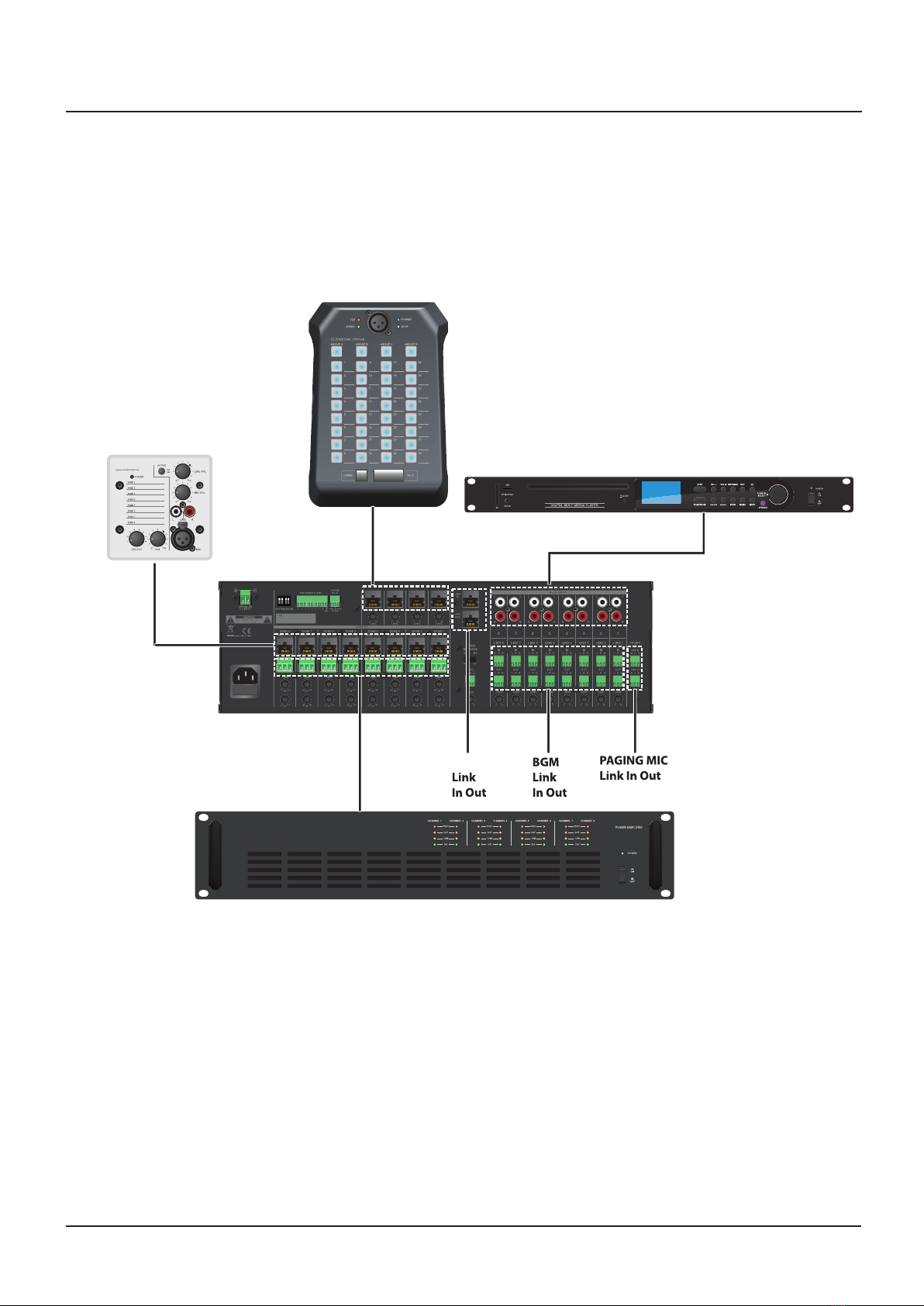
Connections
14
Connections
EM32
WP-8A ER-1 Sound input
CA8240 Power Amplifier
WP-8 A
EM
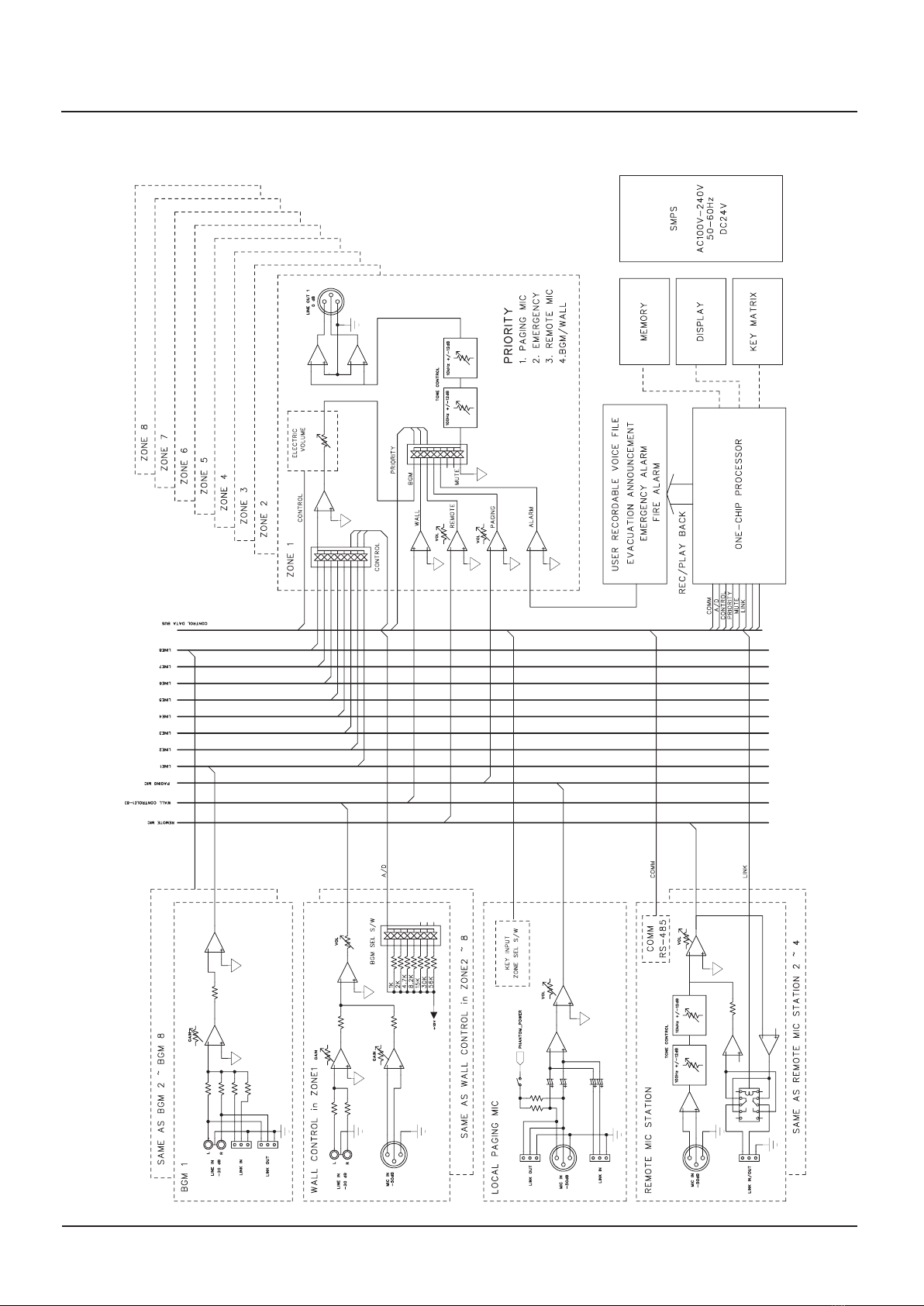
Block diagram
15
Block diagram

Specifications
16
Specifications
Performance
Audio Output
Audio Input
Tone Control
Frequency Response
Signal to Noise Ratio
T.H.D.
Priority Control
Recording Time
Cross Talk
Serial Interface
(RS-485)
Operation Temperature
AC Input
Construction
Power Consumption
Net Weight
Dimensions (W/H/D)
Paging > DRP >EM > WP-8A = BGM
55sec
75dB
Communication Speed
Communication Distance
-10°C ~ +40°C
100-240V 50Hz/60Hz
35W
5.8kg
482 X 132 X 315 mm
Remote Mic Input
Wall Control Input Mic
Wall Control Input Line
BGM 1~8 Input
100Hz
10kHz
Page Mic Input (100Hz ~ 10kHz)
Remote Mic Input (100Hz ~ 10kHz)
Wall Input Mic (100Hz ~ 10kHz)
Wall Input Line Mic (60Hz ~ 15kHz)
Page Mic Input
BGM (60Hz ~ 15kHz)
MIC
BGM
MIC
BGM
0dB(Balanced)
-50dB ± 3dB(Balanced)
-20dB ± 3dB(UnBalanced)
±12dB±1dB
±3dB
Better than 80dB
Better than 65dB
Less than 0.05%
9600bps
Maximum 300m (UTP CAT5)
Necessary modifications are carried out without notice.
This manual suits for next models
2
Table of contents


