Space-Ray PTS 40-N7/L7 User manual

Form 43343530
Aug 2012
INSTALLATION AND OPERATION INSTRUCTIONS
OWNER / INSTALLER: For your s fety this m nu l must be c refully nd thoroughly re d nd
understood before inst lling, oper ting or servicing this he ter.
INFRARED RADIANT TUBE HEATER
Two St ge Push Through System (Positive Pressure)
Models:
PTS SERIES:
(40, 50, 75, 100, 125, 150, 175, 200)
–
N
7/L7
PTU SERIES:
(40, 50, 75, 100, 125, 150, 175, 200)
–
N
7
/L
7
!
INSTALLER
:
This m nu l is the property of the owner. Ple se present this m nu l to the
owner when you le ve the job site.
▲WARNING: Improper inst ll tion, djustment, lter tion, service, or m inten nce c n
c use property d m ge, injury or de th. Re d the inst ll tion, oper tion nd m inten nce
instructions thoroughly before inst lling or servicing this equipment.
IF YOU SMELL GAS: FOR YOUR SAFETY
FOR YOUR SAFETYFOR YOUR SAFETY
FOR YOUR SAFETY
!
!!
!
DO NOT
DO NOTDO NOT
DO NOT try to light ny ppli nce.
!
!!
!DO NOT
DO NOTDO NOT
DO NOT touch ny electric l switch; DO NOT
DO NOTDO NOT
DO NOT use ny
telephone in your building.
!
!!
!IMMEDIATELY
IMMEDIATELYIMMEDIATELY
IMMEDIATELY c ll your g s supplier from neighbor's
telephone. Follow the g s supplier's instructions. If you
c nnot re ch your g s supplier, c ll the fire dep rtment.
DO NOT
DO NOT DO NOT
DO NOT store or use g soline or other
store or use g soline or other store or use g soline or other
store or use g soline or other
fl mm ble v pors nd liquids in the vicinity of
fl mm ble v pors nd liquids in the vicinity of fl mm ble v pors nd liquids in the vicinity of
fl mm ble v pors nd liquids in the vicinity of
this or ny other ppli nce.
this or ny other ppli nce.this or ny other ppli nce.
this or ny other ppli nce.
!IMPORTANT:
!IMPORTANT:!IMPORTANT:
!IMPORTANT:
SAVE THIS MANUAL FOR
SAVE THIS MANUAL FOR SAVE THIS MANUAL FOR
SAVE THIS MANUAL FOR FUTURE REFERENCE.
FUTURE REFERENCE.FUTURE REFERENCE.
FUTURE REFERENCE.
SPACE
SPACESPACE
SPACE-
--
-RAY
RAYRAY
RAY
Post Office Box 36485 (28236) • 305 Doggett Street (28203) • Ch rlotte, North C rolin
Phone (704) 372-6391 • F x (704) 332-5843 • www.sp cer y.com • em il: info@sp cer y.com

Form 43343530
Aug 2012 -1-
TABLE OF CONTENTS
SECTION DESCRIPTION PAGE
1.0) S fety ................................................................................................................................................... 2
2.0) Inst ller Responsibility ...................................................................................................................... 2
3.0) Gener l Inform tion........................................................................................................................... 2
4.0) Minimum Cle r nces to Combustibles ........................................................................................... 4
5.0) Specific tions...................................................................................................................................... 5
6.0) P cking List ......................................................................................................................................... 5
6.1) Accessory P ck ges .......................................................................................................................... 9
7.0) Typic l L youts – PTS/PTU Series ................................................................................................. 11
7.1) Typic l Assembly L yout – (PTS SHOWN) .................................................................................... 12
8.0) Dimensions – PTS Series ................................................................................................................ 13
8.1) Dimensions – PTU Series ................................................................................................................ 14
8.2) He ter Assembly / Joining of Tube Sections ............................................................................... 15
9.0) Typic l Suspension Methods .......................................................................................................... 17
10.0) Assembly of Tube Sections ............................................................................................................. 18
10.1) Assembly of Extension Section ...................................................................................................... 19
10.2) Inserting Turbul tors ........................................................................................................................ 20
10.3) Adding Body Reflectors ................................................................................................................... 21
11.0) Adding Option l 90º Elbow (PTS Only) ......................................................................................... 22
11.1) Adding Option l Corner Reflector (PTS Only) .............................................................................. 22
11.2) Adding 180º U-Bend (PTU Only) .................................................................................................... 23
11.3) Adding Option l U-Bend Reflector (PTU Only) ............................................................................. 23
12.0) Att ching burner screen – (200M BTU MODELS ONLY) ............................................................. 24
12.1) Att ching Burner Box Assembly..................................................................................................... 25
12.2) Connecting the TISS System .......................................................................................................... 26
13.0) G s Connections nd Regul tions ................................................................................................. 29
14.0) Instructions for Pressure Test G uge Connection ....................................................................... 31
15.0) Electric l Connections ..................................................................................................................... 32
16.0) Venting ............................................................................................................................................... 35
17.0) Air for Combustion ........................................................................................................................... 39
17.1) Direct Outside Air for Combustion ................................................................................................. 39
18.0) Lighting nd Shutdown Instructions .............................................................................................. 41
19.0) Sequence of Oper tion .................................................................................................................... 42
20.0) Control Component Loc tion .......................................................................................................... 43
21.0) Cle ning nd Annu l M inten nce ............................................................................................... 44
22.0) Troubleshooting Guide..................................................................................................................... 45
23.0) Repl cing P rts ................................................................................................................................ 48
23.1) Remov l of M in Burner nd Electrodes ...................................................................................... 48
23.2) Removing G s V lve nd M nifold Assembly ............................................................................. 49
23.3) Air Switch Pressure Check .............................................................................................................. 49
23.4) Ignition System Checks ................................................................................................................... 50
24.0) Inst ll tion D t ............................................................................................................................... 51
25.0) Repl cement P rts Guide ............................................................................................................... 52
26.0) W rnings C rd .................................................................................................................................. 56
This he ter complies with ANSI Z83.20 (current st nd rd) nd CSA 2.34. Copies of the N tion l Fuel G s Code (ANSI
Z223.1-l test edition) re v il ble from the CSA t 8501 E st Ple s nt V lley Ro d, Clevel nd, Ohio 44131 or 55 Sc rsd le
Ro d, Don Mills, Ont rio M3B 2R3. All NFPA codes re v il ble from the N tion l Fire Protection Associ tion, B tterym rch
P rk, Quincy, M ss chusetts 02269.

Form 43343530
-2- Aug 2012
1.0) SAFETY
This he ter is self-cont ined infr red r di nt tube he ter. S fety inform tion required during inst ll tion nd
oper tion of this he ter is provided in this m nu l nd the l bels on the product. The inst ll tion, service nd
m inten nce of this he ter must be performed by contr ctor qu lified in the inst ll tion nd service of g s
fired he ting equipment.
All personnel in cont ct with the he ter must re d nd underst nd ll s fety inform tion, instructions nd l bels
before oper tion. The following symbols will be used in this m nu l to indic te import nt s fety inform tion.
W rning
W rningW rning
W rning instructions must be followed to
prevent or void h z rds which
m y c use serious injury, property d m ge or de th.
C ution
C utionC ution
C ution
instructions must be followed to prevent incorrect oper tion or
inst ll tion of
the he ter which m y c use minor injury or property
d m ge.
2.0) INSTALLER RESPONSIBILITY
The inst ller is responsible for the following:
•
••
•The he ter nd venting, s well s electric l nd g s supplies must be inst lled in ccord nce with these
inst ll tion instructions nd ny pplic ble codes nd regul tions.
•
••
•Every he ter sh ll be loc ted with respect to building construction nd other equipment so s to permit
ccess to the he ter.
•
••
•E ch inst ller must follow the cle r nces to combustible m teri ls for the he ters.
•
••
•Inst ll the he ter so th t the supports nd h ngers re correctly sp ced in ccord nce with these
instructions. The he ter must be supported by m teri ls h ving working lo d limit of t le st 115lbs.
•
••
•Ensure th t the tube integrity s fety system TISS™ supplied is inst lled in ccord nce with these instructions
nd th t the tension is correct.
•
••
•Supply the owner with copy of these Inst ll tion nd Oper tion Instructions.
•
••
•Where unvented he ters re used, gr vity or mech nic l me ns sh ll be provided to supply nd exh ust t
le st 4 CFM per 1,000 Btu/hr input of inst lled he ters.
•
••
•Never use the he ter s support for l dder or other ccess equipment. Do not h ng nything from the
he ter.
•
••
•Supply ll inst ll tion m teri ls necess ry th t re not included with the he ter.
•
••
•Check the n mepl te to m ke sure th t the burner is correct for the g s type in the building nd the
inst ll tion ltitude.
3.0) GENERAL INFORMATION
This he ter is self-cont ined infr red r di nt tube he ter for use in loc tions where fl mm ble g ses or v pors
re not gener lly present ( s defined by OSHA ccept ble limits) nd is intended for the he ting of
nonresidenti l
nonresidenti lnonresidenti l
nonresidenti l sp ces.
For indoor inst ll tion only. Not for use in residenti l dwellings.
For indoor inst ll tion only. Not for use in residenti l dwellings.For indoor inst ll tion only. Not for use in residenti l dwellings.
For indoor inst ll tion only. Not for use in residenti l dwellings.
INSTALLATION REQUIREMENTS
INSTALLATION REQUIREMENTSINSTALLATION REQUIREMENTS
INSTALLATION REQUIREMENTS
The inst ll tion must conform to loc l building codes or in the bsence of loc l codes, with the N tion l Fuel G s
Code ANSI Z223.1/NFPA54 or the N tur l G s nd Prop ne Inst ll tion Code CSA B149.1. He ters sh ll be
inst lled by licensed contr ctor or licensed inst ller. Cle r nces to combustibles s outlined in this m nu l
should lw ys be observed. In re s used for stor ge of combustible m teri ls where they m y be st cked
below the he ter, NFPA54 requires th t the inst ller must post signs th t will “specify the m ximum permissible
st cking height to m int in the required cle r nces from the he ter to combustibles.”
Every he ter sh ll be loc ted with respect to building construction nd other equipment so s to permit ccess
to the he ter. E ch inst ller sh ll use qu lity inst ll tion pr ctices when loc ting the he ter nd must give
consider tion to cle r nces to combustible m teri ls, vehicles p rked below, lights, overhe d doors, stor ge
re s with st cked m teri ls, sprinkler he ds, g s nd electric l lines nd ny other possible obstructions or
h z rds. Consider tion lso must be given to service ccessibility.

Form 43343530
Aug 2012 -3-
The he ter, when inst lled in ircr ft h ng rs nd public g r ges, must be inst lled in ccord nce with
ANSI/NFPA 409-l test edition (St nd rd for Aircr ft H ng rs), ANSI/NFPA 88 -l test edition (St nd rd for
P rking Structures), nd ANSI/NFPA 88b-l test edition (St nd rd for Rep ir G r ges) with the following
cle r nces:
. At le st 10 feet bove the upper surf ces of wings or engine enclosures of the highest ircr ft th t m y be
housed in the h ng r nd t le st 8 feet bove the floor in shops, offices, nd other sections of h ng rs
communic ting with ircr ft stor ge or service re s.
b. At le st 8 feet bove the floor in public g r ges. ▲
▲▲
▲WARNING:
WARNING:WARNING:
WARNING: Minimum cle r nces m rked on the he ter
must be m int ined from vehicles p rked below the he ter.
(FOR CANADA ONLY)
.
Inst ll tion of this ppli nce is to be in ccord nce with l test edition of C
SA
B149.1 (
N tur l G s nd
Prop ne Inst ll tion Code).
b. For inst ll tion in public g r ges or ircr ft h ng rs, the minimum cle r nces from the bottom of the
infr red he ter to the upper surf ce of the highest ircr ft or vehicle sh ll be 50 percent gre ter th n the
certified minimum cle r nce, but the cle r nce sh ll not be less th n 8 feet.
Although these he ters m y be used in m ny pplic tions other th n sp ce he ting (e.g., process he ting),
Sp ce-R y will not recognize the w rr nty for ny use other th n sp ce he ting.
This he ter is for Indoor Inst ll tion nd Covered P tio Inst ll tion only nd c n be used in either Vented or
Unvented mode. The term Unvented ctu lly me ns Indirect Vented. While the products of combustion re
expelled into the building, n tion l codes require ventil tion in the building to dilute these products of
combustion. This ventil tion m y be provided by gr vity or mech nic l me ns.
This he ter is not n explosion proof he ter.
This he ter is not n explosion proof he ter.This he ter is not n explosion proof he ter.
This he ter is not n explosion proof he ter. Where the possibility of exposure to vol tile nd low fl sh point
m teri ls exists, it could result in property d m ge or de th. This he ter must not be inst lled in spr y booth
where the he ter c n oper te during the spr ying process. Consult your loc l fire m rsh l or insur nce comp ny.
PTS Series Only:
PTS Series Only:PTS Series Only:
PTS Series Only: Since str ight tube he ters re lw ys hotter t the control end th n t the flue termin l end,
Since str ight tube he ters re lw ys hotter t the control end th n t the flue termin l end, Since str ight tube he ters re lw ys hotter t the control end th n t the flue termin l end,
Since str ight tube he ters re lw ys hotter t the control end th n t the flue termin l end,
lw ys observe the minimum recommended mounting hei
lw ys observe the minimum recommended mounting heilw ys observe the minimum recommended mounting hei
lw ys observe the minimum recommended mounting heights shown on the specific tion sheets
ghts shown on the specific tion sheetsghts shown on the specific tion sheets
ghts shown on the specific tion sheets nd in Section
5.0) of this m nu l. Use U-tube configur tion inste d of str ight tubes for spot or re he ting (e.g., where
single he ter is utilized for sp ce he ting).
WARM
HOT WARM
WARM
WARM
HOT
High Altitud
High AltitudHigh Altitud
High Altitude:
e:e:
e:
Appli nces re supplied s st nd rd for ltitudes of O to 2,000 feet (0-610 m). High- ltitude r tings re obt ined
by ch nge in the orifice size. When ordered for high ltitude inst ll tions, burners re supplied by the f ctory
re dy for high ltitude inst ll tion. Check the n mepl te for ltitude before proceeding with the inst ll tion. In
C n d the djustment for ltitude is m de in ccord nce with St nd rd CGA 2.17, G s-Fired Appli nces for Use
t High Altitudes.

Form 43343530
-4- Aug 2012
4.0) MINIMUM CLEARANCES TO COMBUSTIBLES
Failure to do so may result in death, serious injury or
property damage.
Combustible material must be located outside the
clearance dimensions listed.
Inst ll the w rnings c rd (ordered sep r tely) nd complete the bl nk sp ces using the cle r nces from
combustibles t ble below. See Section 26 for printed copy of the w rnings c rd.
Minimum cle r nces to combustibles sh ll be me sured from the outer surf ces s shown in the following
di gr m:
End End
Ceiling
Below
Front
Rear
45° Angle (Maximum)
* Ceiling
Below
Side Side
Horizontal
MINIMUM CLEARANCES TO COMBUSTIBLES
MINIMUM CLEARANCES TO COMBUSTIBLESMINIMUM CLEARANCES TO COMBUSTIBLES
MINIMUM CLEARANCES TO COMBUSTIBLES
Model No.
Model No.Model No.
Model No.
Mounted Horizont lly
Mounted Horizont llyMounted Horizont lly
Mounted Horizont lly
Angle Mounted t
Angle Mounted t Angle Mounted t
Angle Mounted t
45º
45º45º
45º
Sides
SidesSides
Sides
Ceiling*
Ceiling*Ceiling*
Ceiling*
Below
BelowBelow
Below
Ends
EndsEnds
Ends
45º Front
45º Front45º Front
45º Front
45º Re r
45º Re r45º Re r
45º Re r
PTS/PTU 40
/25
22
”
6”
52
”
15
”
40
”
12”
PTS/PTU 50
/30
22
”
6”
56
”
15
”
48”
12”
PTS/PTU 75
/50
22
”
6”
60”
15
”
52
”
12”
PTS/PTU 100/65 28” 6” 70” ** 15” 58” 12”
PTS/PTU 125/80 28” 6” 76” ** 20” 66” 12”
PTS/PTU 150
/100
34
”
6”
81
” **
20
”
70
”
12
”
PTS/PTU 175
/110
34
”
6”
86
” **
20
”
75
”
12
”
PTS/PTU 200
/125
42
”
6”
93
” **
20
”
80
”
12
”
* When used indirect vented, minimum cle r nce for CEILING must be: 12” for PTS/PTU 50-75 nd 18” for
PTS/PTU 100-200. If option l corner nd u-bend reflectors re not used, the cle r nce must be 18”.
** M ximum cle r nce below reduces by 50% once you re 25ft. downstre m from the burner box.
▲WARNING:
▲WARNING:▲WARNING:
▲WARNING:
Cert in m teri ls or objects, when stored under the he ter, will be subjected to r di nt he t nd
Cert in m teri ls or objects, when stored under the he ter, will be subjected to r di nt he t nd Cert in m teri ls or objects, when stored under the he ter, will be subjected to r di nt he t nd
Cert in m teri ls or objects, when stored under the he ter, will be subjected to r di nt he t nd
could be seriously d m ged. Observe the Minimum Cle r nces to Combustibles listed in the m nu l nd on the
could be seriously d m ged. Observe the Minimum Cle r nces to Combustibles listed in the m nu l nd on the could be seriously d m ged. Observe the Minimum Cle r nces to Combustibles listed in the m nu l nd on the
could be seriously d m ged. Observe the Minimum Cle r nces to Combustibles listed in the m nu l nd on the
he ter t ll times.
he ter t ll times.he ter t ll times.
he ter t ll times.
NOTE:
NOTE:NOTE:
NOTE:
1.
1. 1.
1. The cle r
The cle rThe cle r
The cle r nces specified bove must be m int ined to combustibles nd other m teri ls th t m y be
nces specified bove must be m int ined to combustibles nd other m teri ls th t m y be nces specified bove must be m int ined to combustibles nd other m teri ls th t m y be
nces specified bove must be m int ined to combustibles nd other m teri ls th t m y be
d m ged by temper tures 90ºF bove mbient temper ture. Cle r nces to combustibles re posted on the
d m ged by temper tures 90ºF bove mbient temper ture. Cle r nces to combustibles re posted on the d m ged by temper tures 90ºF bove mbient temper ture. Cle r nces to combustibles re posted on the
d m ged by temper tures 90ºF bove mbient temper ture. Cle r nces to combustibles re posted on the
burner
burnerburner
burner
box. In re s used for stor ge of combustible m teri ls w
box. In re s used for stor ge of combustible m teri ls wbox. In re s used for stor ge of combustible m teri ls w
box. In re s used for stor ge of combustible m teri ls where they m y be st cked below the he ter,
here they m y be st cked below the he ter, here they m y be st cked below the he ter,
here they m y be st cked below the he ter,
NFPA54 requires th t the inst ller must post signs th t will “specify the m ximum permissible st cking height
NFPA54 requires th t the inst ller must post signs th t will “specify the m ximum permissible st cking height NFPA54 requires th t the inst ller must post signs th t will “specify the m ximum permissible st cking height
NFPA54 requires th t the inst ller must post signs th t will “specify the m ximum permissible st cking height
to m int in the required cle r nces from the he ter to combustibles.” Sp ce
to m int in the required cle r nces from the he ter to combustibles.” Sp ceto m int in the required cle r nces from the he ter to combustibles.” Sp ce
to m int in the required cle r nces from the he ter to combustibles.” Sp ce-
--
-R y recommends posting the
R y recommends posting theR y recommends posting the
R y recommends posting these
se se
se
signs dj cent to the he ter thermost t or other suit ble loc tion th t will provide enh nced visibility.
signs dj cent to the he ter thermost t or other suit ble loc tion th t will provide enh nced visibility.signs dj cent to the he ter thermost t or other suit ble loc tion th t will provide enh nced visibility.
signs dj cent to the he ter thermost t or other suit ble loc tion th t will provide enh nced visibility.
2.
2. 2.
2. The st ted cle r nce to combustibles represents surf ce temper ture of 90 ºF (32 ºC) bove room
The st ted cle r nce to combustibles represents surf ce temper ture of 90 ºF (32 ºC) bove room The st ted cle r nce to combustibles represents surf ce temper ture of 90 ºF (32 ºC) bove room
The st ted cle r nce to combustibles represents surf ce temper ture of 90 ºF (32 ºC) bove room
temper ture. Building m teri ls with low he
temper ture. Building m teri ls with low hetemper ture. Building m teri ls with low he
temper ture. Building m teri ls with low he t toler nce (such s pl stics, vinyle siding, c nv s, tri
t toler nce (such s pl stics, vinyle siding, c nv s, trit toler nce (such s pl stics, vinyle siding, c nv s, tri
t toler nce (such s pl stics, vinyle siding, c nv s, tri-
--
-ply, etc.)
ply, etc.) ply, etc.)
ply, etc.)
m y be subject to degr d tion t lower temper tures. It is the inst ller’s responsibility to ssure th t dj cent
m y be subject to degr d tion t lower temper tures. It is the inst ller’s responsibility to ssure th t dj cent m y be subject to degr d tion t lower temper tures. It is the inst ller’s responsibility to ssure th t dj cent
m y be subject to degr d tion t lower temper tures. It is the inst ller’s responsibility to ssure th t dj cent
m teri ls re protected from degr d tion.
m teri ls re protected from degr d tion.m teri ls re protected from degr d tion.
m teri ls re protected from degr d tion.

Form 43343530
Aug 2012 -5-
5.0) SPECIFICATIONS
Model No.
Model No.Model No.
Model No.
Input
InputInput
Input,
, ,
, Btu/hr
Btu/hrBtu/hr
Btu/hr
Combustion
Combustion Combustion
Combustion
Air Pl te
Air Pl teAir Pl te
Air Pl te
P rt #
P rt #P rt #
P rt #
Orifice Size
Orifice SizeOrifice Size
Orifice Size
Minimum *
Minimum *Minimum *
Minimum *
Mounting Height
Mounting HeightMounting Height
Mounting Height
Turbul tor
Turbul tor Turbul tor
Turbul tor
Qty.
Qty.Qty.
Qty.
High
HighHigh
High Low
LowLow
Low N tur l G s
N tur l G sN tur l G s
N tur l G s
Prop ne G s
Prop ne G sProp ne G s
Prop ne G s
@
@@
@
Horizont l
Horizont lHorizont l
Horizont l
@
@@
@
45º Angle
45º Angle45º Angle
45º Angle
PTS/PTU 40/25 40,000
25,000
#44140061
#32 (0.116)
#49 (0.073)
10 ft. 9 ft. 4
PTS/PTU 50/30 50,000
30,000
#44140064
3.5mm
(0.138)
46 (0.081)
11 ft. 10 ft. 5
PTS/PTU 75/50 75,000
50,000
#44140063
#21 (0.159)
2.5mm
(0.098)
13 ft. 12 ft. 5
PTS/PTU 100/65 100,000
65,000
#44140062
#12 (0.189)
#32 (0.116)
14 ft. 13 ft. 3
PTS/PTU 125/80 125,000
80,000
#44140066
#4 (0.209)
#30 (0.129)
14 ft. 13 ft. 7
PTS/PTU 150/100 150,000
100,000
#44140067
“A” (0.234)
#27 (0.144)
15 ft. 14 ft. 4
PTS/PTU 175/110 175,000
110,000
#44140067
“E” (0.250)
#23 (0.154)
16 ft. 15 ft. 0
PTS/PTU 200/125 200,000
125,000
#44140068
6.9mm
(0.272)
4.1mm
(0.161)
18 ft. 16 ft. 1
* MOUNT HEATERS AS HIGH AS POSSIBLE. Minimums re shown s guideline for hum n comfort nd uniform
energy distribution for complete building he ting pplic tions. Consult your Sp ce-R y represent tive for the
p rticul rs of your inst ll tion requirements.
Type
TypeType
Type
G s
G sG s
G s
G s Pipe
G s PipeG s Pipe
G s Pipe
Connection
Connection Connection
Connection
Tube
TubeTube
Tube
Di meter
Di meterDi meter
Di meter
Flue
FlueFlue
Flue
Connection
ConnectionConnection
Connection1
11
1
Fresh Air
Fresh Air Fresh Air
Fresh Air
Connection
ConnectionConnection
Connection1
11
1
Electric l
Electric lElectric l
Electric l
Supply
SupplySupply
Supply
Current
CurrentCurrent
Current
R ting
R tingR ting
R ting
N tur l
or Prop ne
½” MPT
(M le) 4” 4” Round 4” Round
120 Volt,
60Hz,
1 Ph se 1.74 Amp
1 See Section 16.0) for vent sizes when multiple he ters re connected into common vent
Module Electric l R ting:
Module Electric l R ting:Module Electric l R ting:
Module Electric l R ting:
Ignition System (direct sp rk):
Ignition System (direct sp rk):Ignition System (direct sp rk):
Ignition System (direct sp rk):
Input Power
-
Control: 18
-
30 VAC 50/60 Hz (cl ss 2
tr nsformer)
Input Power-Line: 120 VAC (L1, IND cont cts only)
G s V lve R ting: 2.0 A @ 24 VAC (m x.)
Combustion Blower R ting: 3.0 FLA @ 120 VAC
0.0233 H.P. Motor
Fl me Sensitivity: 0.7 micro mps minimum
15 second tri l for ignition period
15 second pre-purge period
60 second inter-purge period
30 second post-purge period
3 tries for ignition (sep r te fl me sensor).
6.0) PACKING LIST
A.
A.A.
A. PTS/PTU Burner P ck ge
PTS/PTU Burner P ck gePTS/PTU Burner P ck ge
PTS/PTU Burner P ck ge
P rt Description
P rt DescriptionP rt Description
P rt Description
QTY
QTYQTY
QTY
Burner Box Assembly (Refer to the following ch rt for P ck ge P rt N
umbers)
..........................
1
4”ID x 4”Lg Flue Ad pter Coll r (#30504500)
................................
................................
..................
1
F stener Kit
–
Burner Box Att chment/Flue Ad pter Coll r (#42907040)
................................
..
1
Cont ining:
#10 x 1/2” Self
-
Drilling Screws (#02189020)
................................
....................
2
¼
-
20 Locknuts (#02167010)
................................
................................
..............
3
Tube Fl nge G sket
(#42921000)
................................
................................
...........
1
Turbul tor 24” Long (#44152240) *See ch rt bove for required qu ntities.
..............................
*
Inst ll tion & Oper tion Instructions
................................
................................
................................
....
1
Turnbuckle
(#30545040)
................................
................................
................................
.........................
1
G s connector 5/8” OD x 36”
(#30302360)
................................
................................
........................
1
Screen Assembly
–
2
-
5/8” ID x 5
-
1/2” Long (#4415101
0)
200M BTU models only
200M BTU models only200M BTU models only
200M BTU models only
.....................
1

Form 43343530
-6- Aug 2012
BURNER PACKAGE NUMB
BURNER PACKAGE NUMBBURNER PACKAGE NUMB
BURNER PACKAGE NUMBERS
ERSERS
ERS
NATURAL GAS
NATURAL GASNATURAL GAS
NATURAL GAS
PROPANE GAS
PROPANE GASPROPANE GAS
PROPANE GAS
MODEL NO.
MODEL NO. MODEL NO.
MODEL NO.
PART NO.
PART NO.PART NO.
PART NO.
MODEL NO.
MODEL NO. MODEL NO.
MODEL NO.
PART NO.
PART NO.PART NO.
PART NO.
PTS/U 40/25-N7 ................. #44149510 PTS/U 40/25-L7 ................... #44149520
PTS/U 50/30-N7 ................. #44149530 PTS/U 50/30-L7 ................... #44149540
PTS/U 75/50-N7 ................. #44149550 PTS/U 75/50-L7 ................... #44149560
PTS/U 100/65-N7 ............... #44149570 PTS/U 100/65-L7 ................ #44149580
PTS/U 125/80-N7 ............... #44149590 PTS/U 125/80-L7 ................ #44149600
PTS/U 150/100-N7............. #44149610 PTS/U 150/100-L7 .............. #44149620
PTS/U 175/110-N7............. #44149630 PTS/U 175/110-L7 .............. #44149640
PTS/U 200/125-N7............. #44149650 PTS/U 200/125-L7 .............. #44149660
B.
B.B.
B. PTS 40
PTS 40PTS 40
PTS 40-
--
-200 Body P ck ge Descriptions
200 Body P ck ge Descriptions200 Body P ck ge Descriptions
200 Body P ck ge Descriptions
(Package Part Number is indicated on the outside of each corresponding carton.)
System
SystemSystem
Systems
ss
s
1
11
1
0Ft.
0Ft. 0Ft.
0Ft.
System
SystemSystem
System
2
22
2
0Ft.
0Ft. 0Ft.
0Ft.
System
SystemSystem
System
3
33
3
0Ft.
0Ft. 0Ft.
0Ft.
System
SystemSystem
System
4
44
4
0Ft.
0Ft. 0Ft.
0Ft.
System
SystemSystem
System
5
55
5
0Ft.
0Ft. 0Ft.
0Ft.
System
SystemSystem
System
PTS Body P ck ges
PTS Body P ck ges PTS Body P ck ges
PTS Body P ck ges –
––
–
Alu
AluAlu
Aluminized/Hot Rolled or
minized/Hot Rolled orminized/Hot Rolled or
minized/Hot Rolled or
Alumi
AlumiAlumi
Alumi-
--
-Therm/Hot Rolled
Therm/Hot Rolled Therm/Hot Rolled
Therm/Hot Rolled
10 Ft.
10 Ft.10 Ft.
10 Ft.
pkg
pkgpkg
pkg
44134020
4413402044134020
44134020
20 Ft. pkg
20 Ft. pkg20 Ft. pkg
20 Ft. pkg
44135000
4413500044135000
44135000
30 Ft. pkg
30 Ft. pkg30 Ft. pkg
30 Ft. pkg
44136000
4413600044136000
44136000
40 Ft. pkg
40 Ft. pkg 40 Ft. pkg
40 Ft. pkg
44137100
4413710044137100
44137100
50 Ft. pkg
50 Ft. pkg50 Ft. pkg
50 Ft. pkg
44138100
4413810044138100
44138100
P rt #
P rt #P rt #
P rt #
E ch Body P ck ge Includes:
E ch Body P ck ge Includes:E ch Body P ck ge Includes:
E ch Body P ck ge Includes:
Qty.
Qty.Qty.
Qty.
Qty.
Qty.Qty.
Qty.
Qty.
Qty.Qty.
Qty.
Qty.
Qty.Qty.
Qty.
Qty.
Qty.Qty.
Qty.
42912080
1
0 Ft. Tube with 24 Hole Fl nge (Aluminized)
1
1
1
-
-
42912169
10 Ft. Tube with 6 Hole Fl nge (Alumi
-
Therm)
-
-
-
1
1
41932101
10 Ft. Tube less Fl nges (Hot Rolled)
-
1
2
3
4
43319100
Reflector, 9’ 11½”
1
2
3
4
5
30462980
Tube Coupling
-
1
2
3
4
43318
000
Tube H nger/Support Br cket, 13”
1
2
3
4
5
43980010
Wire H nger
1
2
3
4
5
Body F stener Kit (included in body p ck ges)
Body F stener Kit (included in body p ck ges)Body F stener Kit (included in body p ck ges)
Body F stener Kit (included in body p ck ges)
42907280
4290728042907280
42907280
42907190
4290719042907190
42907190
42907200
4290720042907200
42907200
42907210
4290721042907210
42907210
42907220
4290722042907220
42907220
42873000
U
-
Bolt
1
2
3
4
5
02127110
Hex Nut, 5/16
-
18
3
5
6
8
10
02189020
HWHSM Sc
rew, #10
-
16 x ½” TEKS
4
8
10
14
18
System
SystemSystem
System
s
ss
s
60Ft. System
60Ft. System60Ft. System
60Ft. System
70Ft. System
70Ft. System70Ft. System
70Ft. System
PTS Body P ck ges
PTS Body P ck ges PTS Body P ck ges
PTS Body P ck ges –
––
–
Alumi
AlumiAlumi
Alumi-
--
-Therm/Hot Rolled
Therm/Hot RolledTherm/Hot Rolled
Therm/Hot Rolled
40 Ft. Pkg
40 Ft. Pkg40 Ft. Pkg
40 Ft. Pkg
44137100
4413710044137100
44137100
20 Ft. Pkg
20 Ft. Pkg20 Ft. Pkg
20 Ft. Pkg
44135010
4413501044135010
44135010
40 Ft. Pkg.
40 Ft. Pkg.40 Ft. Pkg.
40 Ft. Pkg.
44137100
4413710044137100
44137100
30 Ft. Pkg
30 Ft. Pkg30 Ft. Pkg
30 Ft. Pkg
44136040
4413604044136040
44136040
P rt #
P rt #P rt #
P rt #
E ch Body P ck ge Includes:
E ch Body P ck ge Includes:E ch Body P ck ge Includes:
E ch Body P ck ge Includes:
Qty.
Qty.Qty.
Qty.
Qty.
Qty.Qty.
Qty.
Qty.
Qty.Qty.
Qty.
Qty.
Qty.Qty.
Qty.
42912169
10 Ft. Tube with 6 Hole Fl nge (Alumi
-
Therm)
1
-
1
-
41932101
10 Ft. Tube less Fl nges (Hot Rolled)
3
2
3
3
43319100
Reflector, 9’ 11½”
4
2
4
3
30462980
Tube Coupling
3
2
3
3
43318000
Tube H nger/Support Br cket, 13”
4
2
4
3
43980010
Wire H nger
4
2
4
3
Body F stener Kit (included in body p ck ges)
Body F stener Kit (included in body p ck ges)Body F stener Kit (included in body p ck ges)
Body F stener Kit (included in body p ck ges)
42907210
4290721042907210
42907210
42907190
4290719042907190
42907190
42907210
4290721042907210
42907210
42907200
4290720042907200
42907200
42873000
U-Bolt 4 2 4 3
02127110
Hex Nut, 5/16-18 8 5 8 6
02189020
HWHSM Screw, #10
-
16 x ½” TEKS
14
8
14
10

Form 43343530
Aug 2012 -7-
C.
C.C.
C. PTS 40
PTS 40PTS 40
PTS 40-
--
-200 Series Body P ck ge
200 Series Body P ck ge 200 Series Body P ck ge
200 Series Body P ck ge Descriptions
Descriptions Descriptions
Descriptions –
––
–
ALC Option (Aluminized C lorized)
ALC Option (Aluminized C lorized)ALC Option (Aluminized C lorized)
ALC Option (Aluminized C lorized)
(Package Part Number is indicated on the outside of each corresponding carton.)
System
SystemSystem
Systems
ss
s
1
11
1
0Ft.
0Ft. 0Ft.
0Ft.
System
SystemSystem
System
2
22
2
0Ft.
0Ft. 0Ft.
0Ft.
System
SystemSystem
System
3
33
3
0Ft.
0Ft. 0Ft.
0Ft.
System
SystemSystem
System
4
44
4
0Ft.
0Ft. 0Ft.
0Ft.
System
SystemSystem
System
5
55
5
0Ft.
0Ft. 0Ft.
0Ft.
System
SystemSystem
System
PTS Body P ck ges
PTS Body P ck ges PTS Body P ck ges
PTS Body P ck ges –
––
–
Aluminized/
Aluminized/Aluminized/
Aluminized/
Aluminized
AluminizedAluminized
Aluminized
or
oror
or
Alumi
AlumiAlumi
Alumi-
--
-Therm/
Therm/Therm/
Therm/
Aluminized
AluminizedAluminized
Aluminized
10 Ft.
10 Ft.10 Ft.
10 Ft.
pkg
pkgpkg
pkg
44134020
4413402044134020
44134020
20 Ft. pkg
20 Ft. pkg20 Ft. pkg
20 Ft. pkg
44135020
4413502044135020
44135020
30 Ft. pkg
30 Ft. pkg30 Ft. pkg
30 Ft. pkg
44136020
4413602044136020
44136020
40 Ft. pkg
40 Ft. pkg 40 Ft. pkg
40 Ft. pkg
44137090
4413709044137090
44137090
50 Ft. pkg
50 Ft. pkg50 Ft. pkg
50 Ft. pkg
44138080
4413808044138080
44138080
P rt #
P rt #P rt #
P rt #
E ch Body P ck ge Includes:
E ch Body P ck ge Includes:E ch Body P ck ge Includes:
E ch Body P ck ge Includes:
Qty.
Qty.Qty.
Qty.
Qty.
Qty.Qty.
Qty.
Qty.
Qty.Qty.
Qty.
Qty.
Qty.Qty.
Qty.
Qty.
Qty.Qty.
Qty.
42912080
10 Ft. Tube with 24 Hole Fl
nge (Aluminized)
1
1
1
-
-
42912169
10 Ft. Tube with 6 Hole Fl nge (Alumi
-
Therm)
-
-
-
1
1
41932100
10 Ft. Tube less Fl nges (Aluminized)
-
1
2
3
4
43319100
Reflector, 9’ 11½”
1
2
3
4
5
30462980
Tube Coupling
-
1
2
3
4
43318000
Tube H nger/Support Br
cket, 13”
1
2
3
4
5
43980010
Wire H nger
1
2
3
4
5
Body F stener Kit (included in body p ck ges)
Body F stener Kit (included in body p ck ges)Body F stener Kit (included in body p ck ges)
Body F stener Kit (included in body p ck ges)
42907280
4290728042907280
42907280
42907190
4290719042907190
42907190
42907200
4290720042907200
42907200
42907210
4290721042907210
42907210
42907220
4290722042907220
42907220
42873000
U
-
Bolt
1
2
3
4
5
02127110
Hex Nut, 5/16
-
18
3
5
6
8
10
02189020
HWHSM Screw, #10
-
16 x ½” TEKS
4
8
1
0
14
18
System
SystemSystem
System
s
ss
s
60Ft. System
60Ft. System60Ft. System
60Ft. System
70Ft. System
70Ft. System70Ft. System
70Ft. System
PTS Body P ck ges
PTS Body P ck ges PTS Body P ck ges
PTS Body P ck ges –
––
–
Alumi
AlumiAlumi
Alumi-
--
-Therm/
Therm/Therm/
Therm/
Aluminized
AluminizedAluminized
Aluminized
40 Ft. Pkg
40 Ft. Pkg40 Ft. Pkg
40 Ft. Pkg
44137090
4413709044137090
44137090
20 Ft. Pkg
20 Ft. Pkg20 Ft. Pkg
20 Ft. Pkg
44135030
4413503044135030
44135030
40 Ft. Pkg.
40 Ft. Pkg.40 Ft. Pkg.
40 Ft. Pkg.
44137090
4413709044137090
44137090
30 Ft. Pkg
30 Ft. Pkg30 Ft. Pkg
30 Ft. Pkg
44136050
4413605044136050
44136050
P rt #
P rt #P rt #
P rt #
E ch Body P ck ge Includes:
E ch Body P ck ge Includes:E ch Body P ck ge Includes:
E ch Body P ck ge Includes:
Qty.
Qty.Qty.
Qty.
Qty.
Qty.Qty.
Qty.
Qty.
Qty.Qty.
Qty.
Qty.
Qty.Qty.
Qty.
42912169
10 Ft. Tube with
6 Hole Fl nge (Alumi
-
Therm)
1
-
1
-
4193210
0
10 Ft. Tube less Fl nges (Aluminized)
3
2
3
3
43319100
Reflector, 9’ 11½”
4
2
4
3
30462980
Tube Coupling
3
2
3
3
43318000
Tube H nger/Support Br cket, 13”
4
2
4
3
43980010
Wire H nger
4
2
4
3
Bo
BoBo
Body F stener Kit (included in body p ck ges)
dy F stener Kit (included in body p ck ges)dy F stener Kit (included in body p ck ges)
dy F stener Kit (included in body p ck ges)
42907210
4290721042907210
42907210
42907190
4290719042907190
42907190
42907210
4290721042907210
42907210
42907200
4290720042907200
42907200
42873000
U-Bolt 4 2 4 3
02127110
Hex Nut, 5/16-18 8 5 8 6
02189020
HWHSM Screw, #10
-
16 x ½” TEKS
14
8
14
10
D.
D.D.
D. PTU 40
PTU 40PTU 40
PTU 40-
--
-200 Body P ck ge Descriptions
200 Body P ck ge Descriptions200 Body P ck ge Descriptions
200 Body P ck ge Descriptions
(Package Part Number is indicated on the outside of each corresponding carton.)
System
SystemSystem
Systems
ss
s
2
22
2
0Ft.
0Ft. 0Ft.
0Ft.
System
SystemSystem
System
3
33
3
0Ft.
0Ft. 0Ft.
0Ft.
System
SystemSystem
System
4
44
4
0Ft.
0Ft. 0Ft.
0Ft.
System
SystemSystem
System
5
55
5
0Ft.
0Ft. 0Ft.
0Ft.
System
SystemSystem
System
PT
PTPT
PTU
UU
U
Body P ck ges
Body P ck ges Body P ck ges
Body P ck ges –
––
–
Aluminized/Hot Rolled or
Aluminized/Hot Rolled orAluminized/Hot Rolled or
Aluminized/Hot Rolled or
Alumi
AlumiAlumi
Alumi-
--
-Therm/Hot Rolled
Therm/Hot Rolled Therm/Hot Rolled
Therm/Hot Rolled
20 Ft.
20 Ft.20 Ft.
20 Ft.
pkg
pkgpkg
pkg
44135000
4413500044135000
44135000
30 Ft. pkg
30 Ft. pkg30 Ft. pkg
30 Ft. pkg
44136010
4413601044136010
44136010
40 Ft. pkg
40 Ft. pkg 40 Ft. pkg
40 Ft. pkg
44137100
4413710044137100
44137100
50 Ft. pkg
50 Ft. pkg50 Ft. pkg
50 Ft. pkg
44138110
4413811044138110
44138110
P rt #
P rt #P rt #
P rt #
E ch Body P ck ge Includes:
E ch Body P ck ge Includes:E ch Body P ck ge Includes:
E ch Body P ck ge Includes:
Qty.
Qty.Qty.
Qty.
Qty.
Qty.Qty.
Qty.
Qty.
Qty.Qty.
Qty.
Qty.
Qty.Qty.
Qty.
42912080
10 Ft. Tube with 24 Hole Fl nge (Aluminized)
1
1
-
-
42912169
10 Ft. Tube with 6 Hole Fl nge (Alumi
-
Therm)
-
-
1
1
41932101
10 Ft. Tube le
ss Fl nges (Hot Rolled)
1
1
3
3
41932051
5 Ft. Tube less Fl nges (Hot Rolled)
-
2
-
2
43319100
Reflector, 9’ 11½”
2
2
4
4
43319050
Reflector, 4’ 11½”
-
2
-
2
30462980
Tube Coupling
1
3
3
5
43318000
Tube H nger/Support Br cket, 13”
2
4
4
6
43980010
Wire H nger
2
4
4
6

Form 43343530
-8- Aug 2012
Body F stener Kit (included in body p ck ges)
Body F stener Kit (included in body p ck ges)Body F stener Kit (included in body p ck ges)
Body F stener Kit (included in body p ck ges)
42907190
4290719042907190
42907190
42907210
4290721042907210
42907210
42907210
4290721042907210
42907210
42907221
4290722142907221
42907221
42873000
U
-
Bolt
2
4
4
6
02127110
Hex Nut, 5/16
-
18
5
8
8
1
3
02189020
HWHSM Screw, #10
-
16 x ½” TEKS
8
1
4
14
24
U
UU
U-
--
-Bend P ck ge
Bend P ck geBend P ck ge
Bend P ck ge
43208020
4320802043208020
43208020
43208020
4320802043208020
43208020
43208020
4320802043208020
43208020
43208020
4320802043208020
43208020
42913020
U
-
Bend
1
1
1
1
43318500
31” Tube Support/H nger Br cket
1
1
1
1
30462980
Tube Coupling
1
1
1
1
02189020
HWHSM Screw, #10
-
16 x ½” TEKS
2
2
2
2
System
SystemSystem
System
s
ss
s
60Ft. System
60Ft. System60Ft. System
60Ft. System
70Ft. System
70Ft. System70Ft. System
70Ft. System
PT
PTPT
PTU
UU
U
Body P ck ges
Body P ck ges Body P ck ges
Body P ck ges –
––
–
Alumi
AlumiAlumi
Alumi-
--
-Therm/Hot Rolled
Therm/Hot RolledTherm/Hot Rolled
Therm/Hot Rolled
4
44
40 Ft. Pkg
0 Ft. Pkg0 Ft. Pkg
0 Ft. Pkg
44137
4413744137
4413710
1010
100
00
0
20 Ft. Pkg
20 Ft. Pkg20 Ft. Pkg
20 Ft. Pkg
441350
441350441350
4413501
11
10
00
0
40 Ft. Pkg.
40 Ft. Pkg.40 Ft. Pkg.
40 Ft. Pkg.
44137
4413744137
4413712
1212
120
00
0
30 Ft. Pkg
30 Ft. Pkg30 Ft. Pkg
30 Ft. Pkg
441360
441360441360
4413604
44
40
00
0
P rt #
P rt #P rt #
P rt #
E ch Body P ck ge Includes:
E ch Body P ck ge Includes:E ch Body P ck ge Includes:
E ch Body P ck ge Includes:
Qty.
Qty.Qty.
Qty.
Qty.
Qty.Qty.
Qty.
Qty.
Qty.Qty.
Qty.
Qty.
Qty.Qty.
Qty.
42912169
10 Ft. Tube with 6 Hole Fl nge (Alumi
-
Therm)
1
-
1
-
4193210
1
10 Ft. Tube less Fl nges (
Hot Rolled
)
3
2
2
3
41932051
5 Ft. Tube less Fl nges (Hot Rolled)
-
-
2
-
43319100
Reflector, 9’ 11½”
4
2
3
3
43319050
Reflector, 4’ 11½”
-
-
2
-
30462980
Tube Coupling
3
2
4
3
43318000
Tube H nger/Support Br cket, 13”
4
2
5
3
43980010
Wire H nger
4
2
5
3
Body F stener Kit (included in body p ck ges)
Body F stener Kit (included in body p ck ges)Body F stener Kit (included in body p ck ges)
Body F stener Kit (included in body p ck ges)
42907210
4290721042907210
42907210
42907190
4290719042907190
42907190
429072
429072429072
4290722
22
20
00
0
42907200
4290720042907200
42907200
42873000
U-Bolt 4 2 5 3
02127110
Hex Nut, 5/16-18 8 5 10 6
02189020
HWHSM Screw, #10
-
16 x ½” TEKS
14
8
18
10
U
UU
U-
--
-Bend P ck ge
Bend P ck geBend P ck ge
Bend P ck ge
43208020
4320802043208020
43208020
43208020
4320802043208020
43208020
42913020
U-Bend 1 1
43318500
31” Tube Support/H nger Br cket 1 1
30462980
Tube Coupling 1 1
02189020
HWHSM Screw, #10
-
16 x ½” TEKS
2
2
E.
E.E.
E. PTU 40
PTU 40PTU 40
PTU 40-
--
-200 Series Body P ck ge Descriptions
200 Series Body P ck ge Descriptions 200 Series Body P ck ge Descriptions
200 Series Body P ck ge Descriptions –
––
–
ALC Option (Aluminized C lorized)
ALC Option (Aluminized C lorized)ALC Option (Aluminized C lorized)
ALC Option (Aluminized C lorized)
(Package Part Number is indicated on the outside of each corresponding carton.)
System
SystemSystem
Systems
ss
s
2
22
2
0Ft.
0Ft. 0Ft.
0Ft.
System
SystemSystem
System
3
33
3
0Ft.
0Ft. 0Ft.
0Ft.
System
SystemSystem
System
4
44
4
0Ft.
0Ft. 0Ft.
0Ft.
System
SystemSystem
System
5
55
5
0Ft.
0Ft. 0Ft.
0Ft.
System
SystemSystem
System
PT
PTPT
PTU
UU
U
Body P ck ges
Body P ck ges Body P ck ges
Body P ck ges –
––
–
Aluminized/Aluminized or
Aluminized/Aluminized orAluminized/Aluminized or
Aluminized/Aluminized or
Alumi
AlumiAlumi
Alumi-
--
-Therm/Aluminized
Therm/AluminizedTherm/Aluminized
Therm/Aluminized
20 Ft.
20 Ft.20 Ft.
20 Ft.
pkg
pkgpkg
pkg
44135020
4413502044135020
44135020
30 Ft. pkg
30 Ft. pkg30 Ft. pkg
30 Ft. pkg
44136030
4413603044136030
44136030
40 Ft. p
40 Ft. p40 Ft. p
40 Ft. pkg
kg kg
kg
44137090
4413709044137090
44137090
50 Ft. pkg
50 Ft. pkg50 Ft. pkg
50 Ft. pkg
44138090
4413809044138090
44138090
P rt #
P rt #P rt #
P rt #
E ch Body P ck ge Includes:
E ch Body P ck ge Includes:E ch Body P ck ge Includes:
E ch Body P ck ge Includes:
Qty.
Qty.Qty.
Qty.
Qty.
Qty.Qty.
Qty.
Qty.
Qty.Qty.
Qty.
Qty.
Qty.Qty.
Qty.
42912080
10 Ft. Tube with 24 Hole Fl nge (Aluminized)
1
1
-
-
42912169
10 Ft. Tube with 6 Hole Fl nge (Alumi
-
Therm)
-
-
1
1
41932100
10 Ft. Tube less Fl nges (Alumi
nized)
1
1
3
3
41932050
5 Ft. Tube less Fl nges (Aluminized)
-
2
-
2
43319100
Reflector, 9’ 11½”
2
2
4
4
43319050
Reflector, 4’ 11½”
-
2
-
2
30462980
Tube Coupling
1
3
3
5
43318000
Tube H nger/Support Br cket, 13”
2
4
4
6
43980010
Wire H nger
2
4
4
6
Form 43343530
Aug 2012 -9-
Body F stener Kit (included in body p ck ges)
Body F stener Kit (included in body p ck ges)Body F stener Kit (included in body p ck ges)
Body F stener Kit (included in body p ck ges)
42907190
4290719042907190
42907190
42907210
4290721042907210
42907210
42907210
4290721042907210
42907210
42907221
4290722142907221
42907221
42873000
U
-
Bolt
2
4
4
6
02127110
Hex Nut, 5/16
-
18
5
8
8
1
3
02189020
HWHSM Screw, #10
-
16 x ½” TEKS
8
1
4
14
24
U
UU
U-
--
-Bend P ck ge
Bend P ck geBend P ck ge
Bend P ck ge
43208020
4320802043208020
43208020
43208020
4320802043208020
43208020
43208020
4320802043208020
43208020
4320802
43208024320802
43208020
00
0
42913020
U
-
Bend
1
1
1
1
43318500
31” Tube Support/H nger Br cket
1
1
1
1
30462980
Tube Coupling
1
1
1
1
02189020
HWHSM Screw, #10
-
16 x ½” TEKS
2
2
2
2
60Ft. System
60Ft. System60Ft. System
60Ft. System
70Ft. System
70Ft. System70Ft. System
70Ft. System
PT
PTPT
PTU
UU
U
Body P
Body PBody P
Body P ck ges
ck ges ck ges
ck ges –
––
–
Alumi
AlumiAlumi
Alumi-
--
-Therm/Aluminized
Therm/AluminizedTherm/Aluminized
Therm/Aluminized
40 Ft. Pkg
40 Ft. Pkg40 Ft. Pkg
40 Ft. Pkg
44137
4413744137
4413709
0909
090
00
0
20 F
20 F20 F
20 Ft. Pkg
t. Pkgt. Pkg
t. Pkg
441350
441350441350
4413503
33
30
00
0
40 Ft. Pkg.
40 Ft. Pkg.40 Ft. Pkg.
40 Ft. Pkg.
441371
441371441371
4413711
11
10
00
0
30 Ft. Pkg
30 Ft. Pkg30 Ft. Pkg
30 Ft. Pkg
441360
441360441360
4413605
55
50
00
0
P rt #
P rt #P rt #
P rt #
E ch Body P ck ge Includes:
E ch Body P ck ge Includes:E ch Body P ck ge Includes:
E ch Body P ck ge Includes:
Qty.
Qty.Qty.
Qty.
Qty.
Qty.Qty.
Qty.
Qty.
Qty.Qty.
Qty.
Qty.
Qty.Qty.
Qty.
42912169
10 Ft. Tube with 6 Hole Fl nge (Alumi
-
Therm)
1
-
1
-
4193210
0
10 Ft. Tube less Fl nges (
Aluminized
)
3
2
2
3
4193205
0
5 Ft.
Tube less Fl nges (
Aluminized
)
-
-
2
-
43319100
Reflector, 9’ 11½”
4
2
3
3
43319050
Reflector, 4’ 11½”
-
-
2
-
30462980
Tube Coupling
3
2
4
3
43318000
Tube H nger/Support Br cket, 13”
4
2
5
3
43980010
Wire H nger
4
2
5
3
Body F stener Kit (i
Body F stener Kit (iBody F stener Kit (i
Body F stener Kit (included in body p ck ges)
ncluded in body p ck ges)ncluded in body p ck ges)
ncluded in body p ck ges)
42907210
4290721042907210
42907210
42907190
4290719042907190
42907190
429072
429072429072
4290722
22
20
00
0
42907200
4290720042907200
42907200
42873000
U-Bolt 4 2 5 3
02127110
Hex Nut, 5/16-18 8 5 10 6
02189020
HWHSM Screw, #10
-
16 x ½” TEKS
14
8
18
10
U
UU
U-
--
-Bend P ck ge
Bend P ck geBend P ck ge
Bend P ck ge
43208020
4320802043208020
43208020
43208020
4320802043208020
43208020
42913020
U-Bend 1 1
43318500
31” Tube Support/H nger Br cket 1 1
30462980
Tube Coupling 1 1
02189020
HWHSM Screw, #10
-
16 x ½” TEKS
2
2
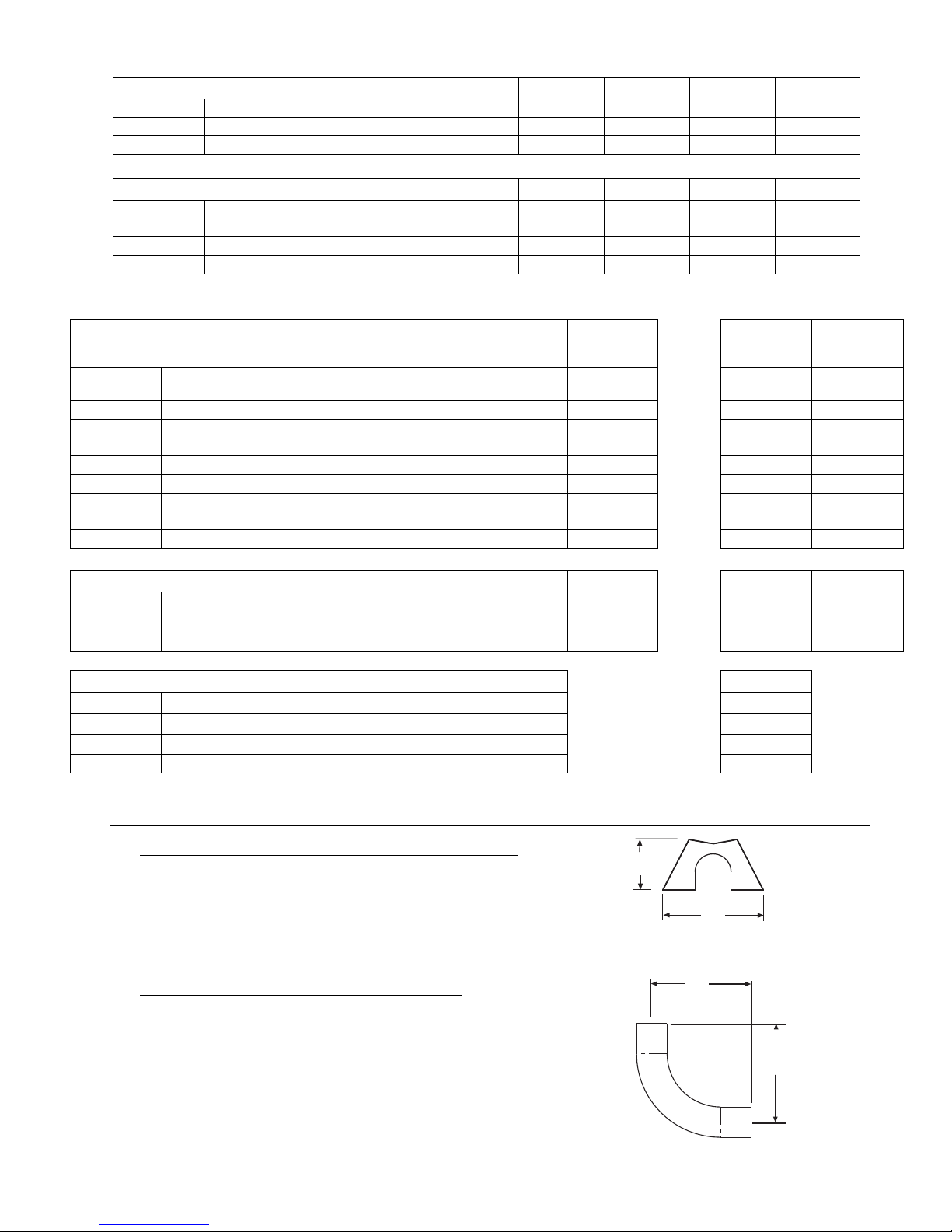
6.1) ACCESSORY PACKAGES
A.
A.A.
A.
End Reflector Accessory P ck ge, P rt #43341010
End Reflector Accessory P ck ge, P rt #43341010End Reflector Accessory P ck ge, P rt #43341010
End Reflector Accessory P ck ge, P rt #43341010
(1 pkg. per PTS Series or 2 pkgs. per PTU Series)
Contains:
End Reflector, #43320000……QTY–2
Speed Clips, #02266010……QTY–8
6
(15cm)
12
(30cm)
END REFLECTOR
B.
B.B.
B.
Elbow Accessory P ck ge, P rt #43208010
Elbow Accessory P ck ge, P rt #43208010Elbow Accessory P ck ge, P rt #43208010
Elbow Accessory P ck ge, P rt #43208010
( ption for PTS Series nly)
Contains:
Elbow, #43175000……QTY–1
#10-16 x ½ Self-Drilling Screws, #02189020……QTY–2
Tube Coupling, #30462980……QTY–1
13
(33cm)
13
(33cm)

Form 43343530
-10- Aug 2012
C.
C.C.
C.
Corner Reflect
Corner ReflectCorner Reflect
Corner Reflect
or Accessory P ck ge, P rt #43342000
or Accessory P ck ge, P rt #43342000or Accessory P ck ge, P rt #43342000
or Accessory P ck ge, P rt #43342000
( ption for PTS Series nly)
Contains:
Corner Reflector Assembly, #43345000……QTY–1
Speed Clips, #02266010……QTY–4
24
(61cm)
24
(61cm)
D.
D.D.
D.
U
UU
U
-
--
-
Bend P ck ge, P rt #43208020
Bend P ck ge, P rt #43208020Bend P ck ge, P rt #43208020
Bend P ck ge, P rt #43208020
( ption for PTU Series nly)
Contains:
U-Bend, #42913020……QTY–1
#10-16 x ½ Self-Drilling Screws, #02189020……QTY–2
Tube Coupling, #30462980……QTY–1
31” Tube Support/H nger Br cket, #43318500……QTY–1
18
(46cm)
E.
E.E.
E.
U
UU
U
-
--
-
Bend Reflector P ck ge, P rt #43488000
Bend Reflector P ck ge, P rt #43488000Bend Reflector P ck ge, P rt #43488000
Bend Reflector P ck ge, P rt #43488000
( ption for PTU Series nly)
Contains:
U-Bend Reflector, #43490000……QTY–1
U-Bend End Reflector, #43490050……QTY–1
Speed Clips, #02266010……QTY–11
#10-16 x ½ Self-Drilling Screws, #02189020……QTY–4
Inst ll tion Form, #43489000……QTY-1
30 3/4 (78cm)
Length = 24 (61cm)
F.
F.F.
F.
31” H nger/Tube Support, P rt #43318500
31” H nger/Tube Support, P rt #4331850031” H nger/Tube Support, P rt #43318500
31” H nger/Tube Support, P rt #43318500
( ption for Angle Mounting of PTU Series)
18
(46cm)
Tube Centers
31
(79cm)
G.
G.G.
G.
Exh ust Hood P ck
Exh ust Hood P ckExh ust Hood P ck
Exh ust Hood P ck
ge, P rt #42924000
ge, P rt #42924000ge, P rt #42924000
ge, P rt #42924000
Contains:
Exh ust Hood Assembly, #42925540……QTY–1
#8-18 x ½ Self-Drilling Screws, #02189030……QTY–2
4 (10cm)
7 1/2
(19cm)
3 3/4 (10cm)
3 1/2 (9cm)
6
(15cm)
Bird
Screen
Side View Front View
H.
H.H.
H.
Rel y
Rel yRel y
Rel y
P ck ge, P rt #4
P ck ge, P rt #4P ck ge, P rt #4
P ck ge, P rt #4
41950
4195041950
41950
00
0000
00
Contains:
Rel y Bo rd, #30740000……QTY–1
ABS Enclosure, #30709059……QTY–
Mounting Pl te, #30709058 QTY-1
W ter Tight Connectors, #30635010 QTY-2
#6-32x5/8” Screws, #02242030 QTY-2

Form 43343530
Aug 2012 -11-
7.0) TYPICAL LAYOUTS – PTS/PTU SERIES
Burner Box
Flue Termination
10 FT. Body Section
30 FT.
SYSTEM
40 FT.
SYSTEM
20 FT.
SYSTEM
50 FT.
SYSTEM
60 FT.
SYSTEM
70 FT.
SYSTEM
10FT.
SYSTEM
5 FT. Body Section
90 Deg. Elbow
180 Deg. U-Bend
LEGEND
MODEL
MODELMODEL
MODEL
EMITTER LENGTH
EMITTER LENGTHEMITTER LENGTH
EMITTER LENGTH
MODEL
MODELMODEL
MODEL
BODY LENGTH
BODY LENGTHBODY LENGTH
BODY LENGTH
Min.
Min.Min.
Min.
M x.
M x.M x.
M x.
Min.
Min.Min.
Min.
M x.
M x.M x.
M x.
PTS 40
/25
10 Ft.
20 Ft.
PTU 40
/25
10 Ft.
10 Ft.
PTS 50
/
30
20 Ft
4
0 Ft.
PTU 50
/30
10 Ft.
20
Ft.
PTS 75
/50
20 Ft.
4
0 Ft.
PTU 75
/50
10 Ft.
20
Ft
PTS 100
/65
30 Ft.
5
0 Ft.
PTU 100
/65
15 Ft.
25
Ft.
PTS 125
/80
30 Ft
6
0 Ft.
PTU 125
/80
15 Ft.
30
Ft.
PTS 150
/100
40 Ft.
60 Ft.
PTU 150
/100
20 Ft.
30 Ft.
PTS 175
/110
5
0 Ft.
70 Ft.
PTU 175
/110
25 Ft.
35 Ft.
PTS 200
/125
50 Ft.
70 Ft.
PTU 200
/125
25 Ft.
35 Ft.
NOTES:
NOTES:NOTES:
NOTES:
1. In ll configur tions, the control unit must be connected directly to either ) the 24-hole fl nge of the 10 ft.
luminized steel st rting body section (for 10 ft., 20 ft., nd 30 ft. systems) or b) the 6-hole fl nge of the 10
ft. lumi-therm steel st rting body section (for 40 ft., 50 ft., 60 ft., nd 70 ft. systems).
2. Joining of two 90º elbows directly together to form “Z” sh pe IS NOT permitted.
3. PTS/U 175/110 - 40 ft length v il ble for speci l pplic tions.
4. 5 Ft. Body P ck ges m y be utilized on ny of these he ters to yield he ter lengths from 15 ft. to 70 ft.
5. Any configur tion of components not shown in the illustr tions m y be used except s noted in 1 nd 2
bove.

Form 43343530
-12- Aug 2012
7.1) TYPICAL ASSEMBLY LAYOUT – (PTS SHOWN)
Failure to do so may result in death, serious injury, property damage or illness
from Carbon Monoxide poisoning.
The heater must be assembled with the correct number of turbulator sections
and tube length for the rated heat input.
The turbulator must be installed in the last tube section as shown.
POISONOUS GAS AND SOOT HAZARD
60 FT. SYSTEM
50 FT. SYSTEM
20 FT. SYSTEM
30 FT. SYSTEM
40 FT. SYSTEM
LEGEND
Burner Box 10ft Aluminized Tube 24
Hole Flange
or
10ft Alumi-Therm Tube
6 Hole Flange
Coupling 10ft Aluminized or HRS
Tube model dependent
2ft Aluminized
Steel
Turbulator
sections
70 FT. SYSTEM
10 FT. SYSTEM
2ft Stainless
Steel
Turbulator
sections
Stainless Steel Turbulator
closest to burner PTS / U
40/25 only.
Model
PTS/U 40/25
PTS/U 50/30
PTS/U 75/50
PTS/U 100/65
PTS/U 125/80
PTS/U 150/100
PTS/U 175/110
PTS/U 200/125
2 Ft. Turbulator
Sections
4
5
5
3
7
4
0
1
Form 43343530
Aug 2012 -13-
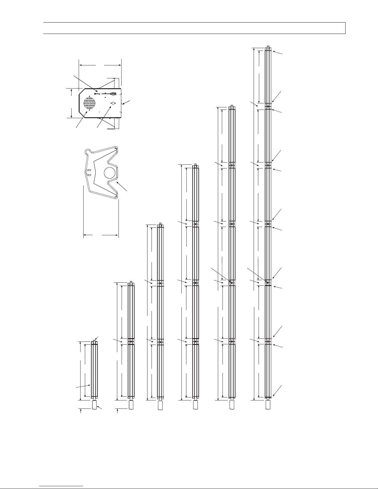
8.0) DIMENSIONS – PTS SERIES
Typic l Dimensions Up to 60 Ft. Shown.
Burner
Box
13 Tube Support/
Hanger Bracket
Wire Hanger
4 Tube Coupling
(typical)
Bottom View
Wire Hanger
Wire Hanger 13 Tube Support/
Hanger Bracket
13 Tube Support/
Hanger Bracket
108
(274cm)
720
(1829cm)
108
(274cm)
108
(274cm) 108
(274cm)
108
(274cm)
12
(30cm)
12
(30cm) 12
(30cm)
Wire Hanger
Wire Hanger 13 Tube Support/
Hanger Bracket
13 Tube Support/
Hanger Bracket Wire Hanger
13 Tube Support/
Hanger Bracket
108
(274cm)
12
(30cm)
12
(30cm)
4 Tube Coupling
(typical)
Bottom View
108
(274cm)
600
(1524cm)
108
(274cm)
108
(274cm) 108
(274cm)
108
(274cm)
12
(30cm)
12
(30cm) 12
(30cm)
12
(30cm)
108
(274cm)
Models:
PTS 40/25 - 75/50
14
(36cm) 108
(274cm)
240
(610cm)
12
(30cm)
108
(274cm)
480
(1219cm)
108
(274cm)
12
(30cm)
108
(274cm)
108
(274cm)
12
(30cm)
Models:
PTS 50/30 - 125/80
360
(914cm)
108
(274cm)
12
(30cm)
12
(30cm)
108
(274cm)
108
(274cm)
Flue
Terminal
10 FT Tube
Assembly
(typical)
Models:
PTS 40/25
14
(36cm) 108
(274cm)
120
(305cm)
10
(25cm)
14-1/2
(37cm)
Fresh Air
Inlet
1/2 MPT Gas
Connection
9-1/4
(24cm)
End View
Flue Terminal Burner
Box
120VAC
Power Supply Cord
Models:
PTS 50/30 - 150/100
Models:
PTS 100/65 - 200/125
Models:
PTS 125/80 - 200/125

Form 43343530
-14- Aug 2012
8.1) DIMENSIONS – PTU SERIES
Typic l Dimensions Up to 50 Ft. Shown.
Models:
PTU 40/25 - 75/50
Models:
PTU 50/30 - 125/80
Models:
PTU 50/30 - 175/110
Models:
PTU 100/65 - 200/125
300
(762cm)
108
(274cm)
12
(30cm)
12
(30cm)
Bottom View
Wire Hangers
(typical)
108
(274cm)
12
(30cm)
240
(610cm) 108
(274cm)
180
(457cm) 108
(274cm)
12
(30cm)
48
(122cm)
5 FT Tube
Assembly
14
(36cm)
120
(305cm)
108
(274cm)
Burner
Box
Flue
Terminal
10 FT Tube
Assembly
(typical)
15
(38cm)
108
(274cm)
48
(122cm)
31 Tube Support/
Hanger Brackets
(typical at control end)
Shipped with
U-Bend Package
Wire Hangers
(typical)
U-Bend
13 Tube Support/
Hanger Brackets
(typical)
4 Tube Coupling
(typical)
13 Tube Support/
Hanger Brackets
(typical)
6
(16cm)
Flue Terminal 18 (46cm)
31 (79cm)
End View
Burner
Box
U-Bend
31 Tube Support/
Hanger Bracket
10
(25cm)
14-1/2
(37cm)
Fresh Air
Inlet
1/2 MPT Gas
Connection
120VAC
Power Supply Cord

Form 43343530
Aug 2012 -15-
8.2) HEATER ASSEMBLY / JOINING OF TUBE SECTIONS
Typical Assembly Overview
(
PTS
40FT Shown)
4"OD x 10Ft.
Tube
See section
7
for required tubes.
Tube Support Bracket
U-Bolt Clamp &
5/16" Hex Nuts
Mounting
Flange
24 Hole for Aluminized Steel Tubes
6 Hole for Alumi-Therm Steel Tubes
Wire Hanger
Gasket
Burner
Box
Flue
Terminal
5 hanging points to be used for suspension for a typical 40ft
long system. There must be two hanging points on the first
tube and one on each of the other tubes
Maximum 6 distance
from control box to the
tube support/hanger
bracket.
8 - 9 ¼
8 - 10
8 - 10
Not More
Than 10
#10 Self-Drill Screws
(Typical all tube supports,
tube couplings and flue
terminal.)
Typical
Overlap
Turbulator
(See specifications
section 5 for required
quantities.)
Tube Coupling
(Typical each tube joint
.
)
Burner Box
Suspension
Chain
3
(
burner
box to reflector)
2
overlap
1
overlap
1
overlap

Form 43343530
-16- Aug 2012
Typical Assembly Overview
(PTU 40FT Shown)
Wire Hanger
Flue
Terminal
#10 Self-Drill Screws
(Typical all tube supports,
tube couplings and flue
terminal.)
4"OD x 10Ft. Tube
See section 7
for required tubes.
13 Tube Support Brk.
with U-Bolt Clamp
& 5/16" Hex Nuts
Mounting Flange
24 Hole for Aluminized Steel Tubes
6 Hole for Alumi-Therm Steel Tubes
Gasket
Burner Box
Typical
Overlap
U-Bend
Tube Coupling
(Typical each tube joint.)
Reflector
31 Tube Support Brk.
with U-Bolt Clamp
& 5/16" Hex Nuts
8 - 10
6 hanging points to be used for suspension for a typical
40ft long system. There must be two hanging points
on the first tube and one on each of the other tubes
Maximum 6 distance
from burner box to the
tube support/hanger
bracket.
8 - 9 ¼
#10 Self-Drill
Screws
(2 each)
Turbulator
(See specifications
section 5 for required
quantities.)
Burner Box
Suspension
Chain

Form 43343530
Aug 2012 -17-
9.0) TYPICAL SUSPENSION METHODS
Burner must be secured to the mounting flange with nuts.
All materials used to suspend the heater must have a minimum working load
of 115 lbs.
All S Hooks must be crimped closed.
Never use the heater to support a ladder or other access equipment.
Failure to do so may result in death, serious injury or property damage.
SUSPENSION HAZARD
V rious me ns of suspending the he ter c n be used. See the following dr wings for typic l ex mples.
1. Use only noncombustible m teri ls for suspending h ngers nd br ckets.
2. A minimum No. 2 ch in with working lo d limit of 115 lbs. is required.
3. Turnbuckles c n be used with ch ins to llow leveling of the he ter. All “S” hooks nd eye bolts must be
m nu lly crimped closed by the inst ller.
4. When using rigid me ns for he ter suspension (rod, fl t b r, etc.) provide sufficient lengths or swing joints to
compens te for exp nsion. See Figures b nd c.
5. He ters subject to vibr tion must be provided with vibr tion isol ting h ngers.
6. He ters must not be supported by g s or electric supply lines nd must be suspended from perm nent
structure with dequ te lo d c p city.
Sp ce-R y recommends th t the body sections be suspended using ch ins with turnbuckles. This will llow
slight djustments fter ssembly nd he ter exp nsion/ contr ction during oper tion.
If “tr peze” method is used for tube support/h nger br ckets (shown below), the minimum ch in length for the
two connecting ch ins is 36” to minimize ny vibr tion th t might be gener ted by the burner box. If these
ch ins must be less th n 36”, then do not use the tr peze method nd, inste d, use individu l ch ins on e ch
tube support/h nger br cket.
Eyebolt
Turnbuckle
Minimum
No. 2 Chain
Eyebolt
c.
Threaded
Rod
Turnbuckle
Eyebolt
b.
3/16 x 1
wideFlat Bar
Minimum
No. 2 Chain
a.
S-Hook crimped
closed (typical)
Wire Hanger
Wire
Hanger
36 (91cm) Minimum
Tube Support/
Hanger Bracket
d.
Failure to install the burner box suspension
chain vertically will void the manufacturers
warranty.
Burner Box Suspension
Eye bolt
Turnbuckle

Form 43343530
-18- Aug 2012
10.0) ASSEMBLY OF TUBE SECTIONS
Sheet metal parts, particularly reflectors and vent have sharp
edges. Always use gloves when handling.
Failure to do so may result in death, serious injury or property
damage.
CUT HAZARD
During field ssembly of the he ter body sections, the recommended procedure is s follows:
1. Before h nging he ter sections, first determine the ctu l l yout of the system (see Sections 7.0) & 8.0) for
det ils). Consider tion must lso be t ken for flue pipe, fresh ir ducting, g s piping, cle r nces to
combustibles, etc. before h nging he ter. Typic l suspension methods re shown in Section 9.0).
2. H ng e ch tube section individu lly. DO NOT tt ch the he ter tube sections together on the ground nd
ttempt to h ng the entire system.
3. In ll configur tions, the burner box must be connected directly to either ) the 24-hole fl nge of the 10 ft.
luminized steel st rting body section (for 10 ft., 20 ft., nd 30 ft. systems) or b) the 6-hole fl nge of the 10
ft. lumi-therm steel st rting body section (for 40 ft., 50 ft., 60 ft., nd 70 ft. systems.
4. Assemble tube support/h nger br cket 4” from the end of the he t exch nger tube h ving the mounting
fl nge. Align the tube such th t the welded se m is f cing down tow rd the ground.
F
FF
F ilure to ssemble the tube with the se m f cin
ilure to ssemble the tube with the se m f cinilure to ssemble the tube with the se m f cin
ilure to ssemble the tube with the se m f cin
g down will VOID the
g down will VOID the g down will VOID the
g down will VOID the
m nuf cturer’s w rr nty.
m nuf cturer’s w rr nty. m nuf cturer’s w rr nty.
m nuf cturer’s w rr nty.
Weld seam to the
bottom of tube.
END VIEW
4"OD x 10Ft. Heat
Treated Aluminized
Steel Tube
Control Box
Mounting Flange
1
2
8 to 9 1/4
Maximum 6 distance from
control box mounting flange
to tube support bracket.
Tube Support/
Hanger Bracket
Wire Hanger
U-Bolt Clamp
& 5/16 Hex Nuts
S Hooks
5. Suspend the ch in to tt ch the wire h nger nd the tube support br cket. Insert the tube into the wire
h nger nd then r ise the tube support br cket end up to the suspension ch in, use “S” hooks to tt ch the
wire h nger nd tube support br cket to the ch in.

Form 43343530
Aug 2012 -19-
10.1) ASSEMBLY OF EXTENSION SECTION
MIN 8 MAX 10 BETWEEN HANGERS
1
2
Tube Support/
Hanger Bracket
Wire Hanger
Coupling
U-Bolt Clamp
& 5/16 Hex Nuts
Tube Support/
Hanger Bracket
3
6 approx.
See typic l ssembly overview (Section 8.0) for typic l complete ssembly. Assemble ddition l extension
sections s required for ll systems. (See Sections 7.0), nd 8.0) for typic l l yout det ils.)
Join the tube sections together nd secure with tube couplings s described below:
T
TT
T
he following
he followinghe following
he following
coupling
couplingcoupling
coupling
tightening instructions MUST
tightening instructions MUSTtightening instructions MUST
tightening instructions MUST
b
bb
b
e
e e
e
followed properly to ensure the integrity of the tube
followed properly to ensure the integrity of the tube followed properly to ensure the integrity of the tube
followed properly to ensure the integrity of the tube
connections. Two #10 self
connections. Two #10 selfconnections. Two #10 self
connections. Two #10 self-
--
-drilling screws
drilling screws drilling screws
drilling screws MUST
MUSTMUST
MUST
be inst lled
be inst lled be inst lled
be inst lled
t every coupling s shown in the instructions below. F ilure
t every coupling s shown in the instructions below. F ilure t every coupling s shown in the instructions below. F ilure
t every coupling s shown in the instructions below. F ilure
to do so m y result in serious injury or property d m ge.
to do so m y result in serious injury or property d m ge.to do so m y result in serious injury or property d m ge.
to do so m y result in serious injury or property d m ge.
1. Pl ce the compression coupling over the end of the tube.
2. Use the sm ll hole t the centerline of the coupling to check th t the coupling is inserted correctly.
3. P rti lly tighten the bolt ne rest the end of the tube ( pproxim tely h lf closed).
Tube
Coupling
1
Center end of
Tube with hole
Partially tighten this bolt
Tube
2
3
This manual suits for next models
7
Table of contents
Popular Swimming Pool Heater manuals by other brands

EcoOnline
EcoOnline PoolMasterpro Installation and user manual

Sig Marine
Sig Marine Cozy Cabin Solid Fuel Heater Operating and installation instruction manual

Rheem
Rheem Raypak ELS 0018 Installation and operation manual

Thermalec
Thermalec 24THR instruction manual

Raypak
Raypak CROSSWIND Series Installation and operation manual

Raypak
Raypak 406A Installation and operation manual


