SPE EXPERT 1K-FA User manual

EXPERT 1K-FA
1KW SOLID STATE FULLY AUTOMATIC
LINEAR AMPLIFIER
USER’S MANUAL

User’s manual EXPERT 1K-FA
Pag. 2 of 42

User’s manual EXPERT 1K-FA
Pag. 3 of 42
Main index
IMPORTANT ......................................................................................................................................................4
PRECAUTIONS..................................................................................................................................................4
UNPACKING ......................................................................................................................................................6
1.
PANEL DESCRIPTION ....................................................................................................................7
1.1
Front Panel .......................................................................................................................................7
1.2
Rear Panel........................................................................................................................................8
2.
GENERAL INFORMATION ..............................................................................................................9
2.1
Power supply ....................................................................................................................................9
2.2
Input / Output ....................................................................................................................................9
2.3
ALC / RELAY / CAT..........................................................................................................................9
3.
INTERCONNECTION WITH THE TRANSCEIVER .......................................................................11
4.
USE OF THE LINEAR AMPLIFIER ................................................................................................12
5.
EXTERNAL GROUND CONNECTION ..........................................................................................13
6.
ANTENNA.......................................................................................................................................13
7.
POWER SUPPLY...........................................................................................................................14
7.1
Mains cable termination..................................................................................................................14
8.
TUNER ...........................................................................................................................................16
9.
PROTECTIONS / ALARMS............................................................................................................17
10.
PROGRAMMING............................................................................................................................19
10.1
Ways to operate .............................................................................................................................19
11.
INITIAL OPERATION OF THE AMPLIFIER...................................................................................22
11.1
Initial Programming.........................................................................................................................22
11.2
Operating ........................................................................................................................................23
12.
CAT CONNECTIONS.....................................................................................................................25
12.1
CAT Connector...............................................................................................................................25
12.2
SPE.................................................................................................................................................25
12.3
ICOM ..............................................................................................................................................26
CAT CI–V Interface ........................................................................................................................26
BAND CONTROL VOLTAGE Interface..........................................................................................26
12.4
KENWOOD.....................................................................................................................................27
CAT RS232 Interface .....................................................................................................................27
CAT 5V TTL Interface.....................................................................................................................27
12.5
YAESU............................................................................................................................................28
CAT RS232 Interface .....................................................................................................................28
CAT 5V TTL Interface.....................................................................................................................28
BAND DATA Interface ....................................................................................................................29
12.6
TRANSCEIVERS OF OTHER BRANDS........................................................................................29
13
OTHER CONNECTIONS ...............................................................................................................30
13.1
ALC, RELAY CONNECTIONS .......................................................................................................30
13.2
REMOTE ON LINK.........................................................................................................................30
13.3
TX INH LINK ...................................................................................................................................31
14.
TRANSCEIVER CONTROLLED WITH A PC.................................................................................32
14.1
ICOM CI-V INTERFACE................................................................................................................32
14.2
RS232 INTERFACE .......................................................................................................................33
14.3
5V TTL KENWOOD INTERFACE ..................................................................................................33
14.4
5V TTL YAESU INTERFACE .........................................................................................................34
15.
USE OF THE RS-232 PORT..........................................................................................................35
16.
MAINTENANCE .............................................................................................................................36
17.
CHARACTERISTICS / SPECIFICATIONS ....................................................................................37
18.
TABLE ............................................................................................................................................39
19.
WARRANTY ...................................................................................................................................40
User’s manual EXPERT 1K-FA
Pag. 4 of 42
Congratulations for choosing the SPE EXPERT 1K-FA linear amplifier It is small, and
powerful, it covers the whole frequency range from 1.8 to 50 MHz, completely
automatically. All operating conditions (frequency, antenna and tuner) may be controlled
from your transceiver. It is possible to connect it to every type of device, it is extremely
user-friendly, and offers a product which is best-in-class.
IMPORTANT
Read this instruction manual carefully before attempting to operate the linear
amplifier.
Keep this manual. It contains important safety and operating instructions for the
SPE EXPERT 1K-FA.
PRECAUTIONS
Explicit definitions
WORD DEFINITION
WARNING!
Risk of danger of fire or electric shock to persons.
Possible damage to the amplifier.
NOTE:
Serious problems if not observed. Danger of fire or electric shock for the operator, or
damage to the equipment.
WARNING!
HIGH VOLTAGE! DO NOT disconnect an antenna from the amplifier during
transmission; Electric shock or fire is possible.
WARNING!
DO NOT modify the internal wiring of the amplifier. Any modifications will invalidate the
warranty,and may reduce the performance of the linear amplifier or damage it.
WARNING!
Before using the linear amplifier, compare the value of voltage of the local mains supply
network with the value required by the amplifier, and set it up correctly.
WARNING!
DO NOT turn ON the linear amplifier unless it has been properly grounded through the
green/yellow conductor of the mains cord. Your dealer will already have provided the
correct mains plug for your local electricity network, with the earth pin connected to that
conductor. Do not disconnect this under any circumstances, or there is a risk of severe
or fatal electric shock.
WARNING!
DO NOT use an extension cord with the AC power cable, as if it is not correctly rated
there is a risk of fire or electric shock.
WARNING!
DO NOT allow metallic objects or wires to enter inside the amplifier.
User’s manual EXPERT 1K-FA
Pag. 5 of 42
WARNING!
DO NOT obstruct the entries for cooling air at both the sides of the amplifier.
Ensure that no object impedes the correct operation of the fans.
WARNING!
DO NOT expose the linear amplifier to rain, snow or any liquids.
WARNING!
DO NOT instal the linear amplifier in a place without good ventilation. This could limit
heat dissipation and the amplifier could be damaged.
WARNING!
DO NOT touch the amplifier with damp or wet hands. There is danger of electric shock.
Avoid opening it before you have disconnected it from the mains supply, then wait at
least 2 minutes for electrolytic capacitors to complete their discharge.
To clean the amplifier DO NOT use chemical agents like alcohol or benzene because
the plastic surfaces could be damaged.
AVOID using the amplifier in areas with temperatures below –10° C (+14°F) or above
+40°C (+104°F).
AVOID using the linear amplifier in locations that are very dusty, damp or in direct
sunlight.
AVOID placing the linear amplifier against walls, the circulation of the air would be
obstructed and the noise of the fans would be reflected toward the operator.
AVOID permitting children to play with the amplifier.
If you do not use the linear amplifier for long time, set the back main switch [I/O] to the
OFF position [O].
This amplifier should only be operated by persons who have an appropriate radio
transmitting licence, and you should observe your licence conditions whilst
using it.
User’s manual EXPERT 1K-FA
Pag. 6 of 42
UNPACKING
Remove the packing and carefully check the contents.
If you find any damage or if there are any parts missing, contact your retailer
immediately.
Keep the shipping cartons for future transportation if required.
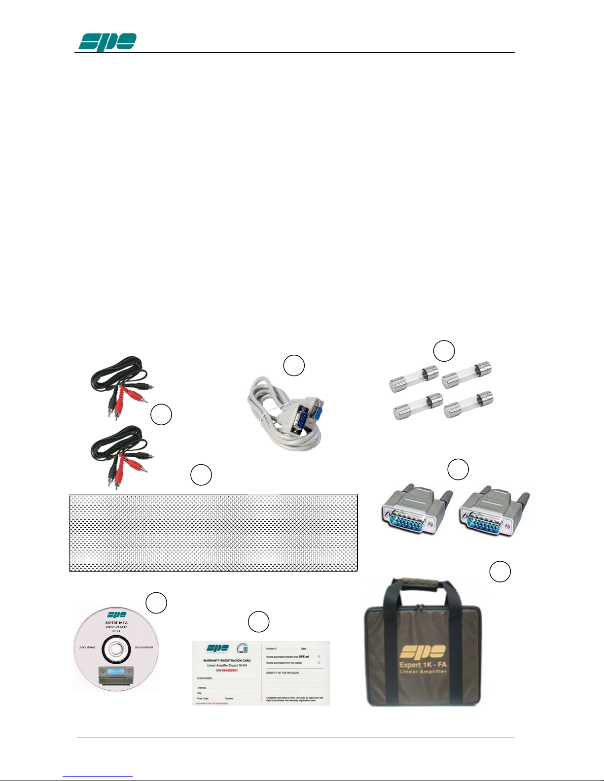
Accessories included in the carton
a) Transport carry bag.
b) 2 - cables with RCA (phono) connectors for ALC, RELAY links.
c) 1 - standard RS232 cable.
d) 2 -15 pole connectors (DB-15) for CAT links.
e) User manual.
f) Spare fuses:
1 – 12.5 A.
1 – 0,5 A.
1 - 20 A (USA and Japan only).
1 - 1 A. (USA and Japan only).
g) Spare air filter.
h) Certificate of compliance and warranty form.
b
c
d
e
a
h
f
g
User’s manual EXPERT 1K-FA
Pag. 7 of 42
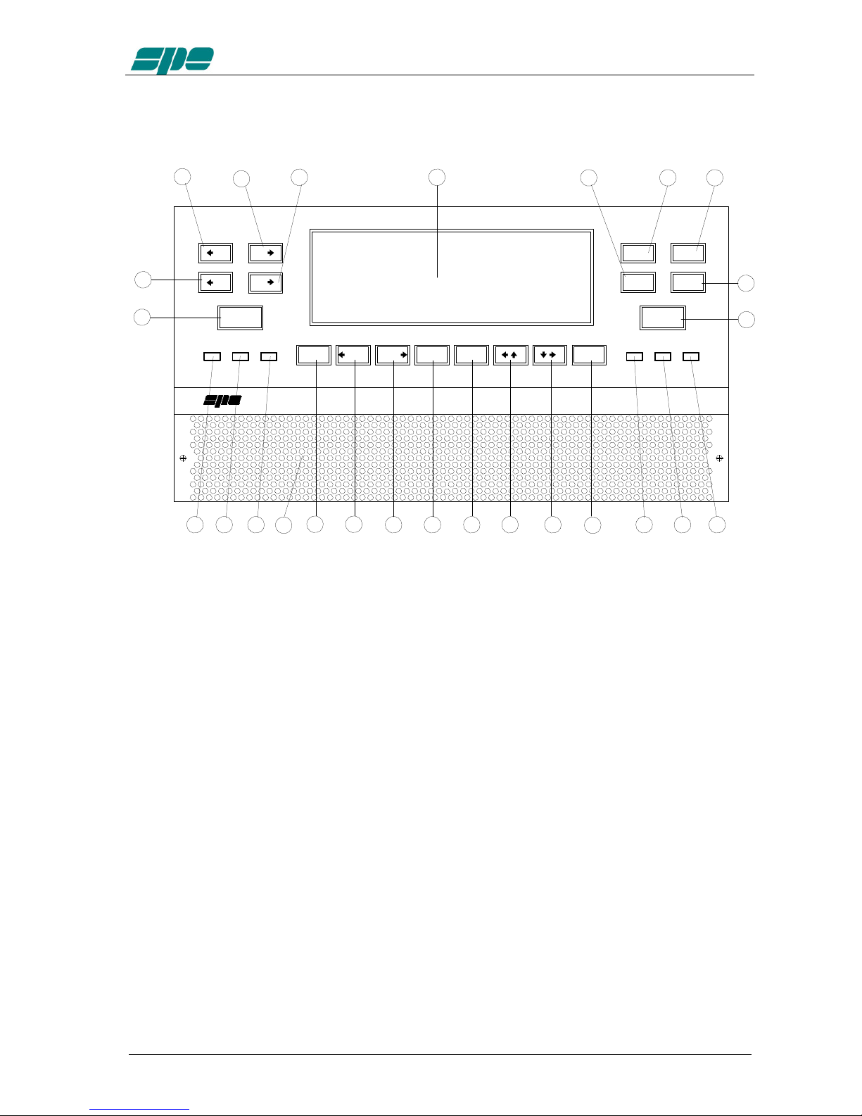
1. PANEL DESCRIPTION
1.1 Front Panel
SET
SETSET
SET
CAT
CATCAT
CATANT
ANTANT
ANTBAND
BANDBAND
BANDBAND
BANDBAND
BANDINPUT
INPUTINPUT
INPUT
TUNE
TUNETUNE
TUNEALL
ALLALL
ALL SET
SETSET
SET ON
ONON
ON OP
OPOP
OP TX
TXTX
TX
1
11
12
22
2
3
33
3
4
44
4
5
55
5
25
2525
25
1.8 -50 MHz Solid State
Fully Automatic Linear Amplifier
Expert 1K - FA
21
2121
21 20
2020
20 19
1919
19
6
66
6
7
77
78
88
813
1313
1311
1111
11
10
1010
109
99
9
22
2222
2223
2323
2324
2424
24 26
2626
26
16
1616
16
18
1818
18
17
1717
17
15
1515
15
14
1414
14
L
LL
L
C
CC
C C
CC
C
L
LL
L
TUNE
TUNETUNE
TUNE
OFF
OFFOFF
OFF ON
ONON
ON
POWER
POWERPOWER
POWER
DISPLAY
DISPLAYDISPLAY
DISPLAY
OPERATE
OPERATEOPERATE
OPERATE
12
1212
12
1) ON
2) OFF
3) DISPLAY switches between display pages.
4) POWER switches output power from “FULL / HALF“ (1KW / 500 W).
5) OPERATE switches between Standby / Operate.
6) SET used to program the amplifier.
7) ►▼ used to program the amplifier.
8) ◄▲ used to program the amplifier.
9) INPUT selects one of the two inputs of the amplifier.
10) ◄BAND switches bands manually (downward in frequency).
11) BAND ►switches bands manually (upward in frequency).
12) ANT shows the current Antenna / Band setting.
13) CAT shows the current CAT interface setting.
14) TUNE: starts the automatic tuning process.
15) ◄C used for manual tuning.
16) C ►used for manual tuning.
17) ◄L used for manual tuning.
18) L ►used for manual tuning.
19) TX red led, illuminates during transmission.
20) OP yellow led, illuminates when the amplifier is in “Operate” state.
21) ON green led, illuminates when the amplifier is “ON”.
22) SET green led, illuminates during programming.
23) TUNE yellow led, illuminates during tuning.
24) ALL red led, illuminates when there is an alarm.
25) DISPLAY
26) AIRFLOW GRID
User’s manual EXPERT 1K-FA
Pag. 8 of 42
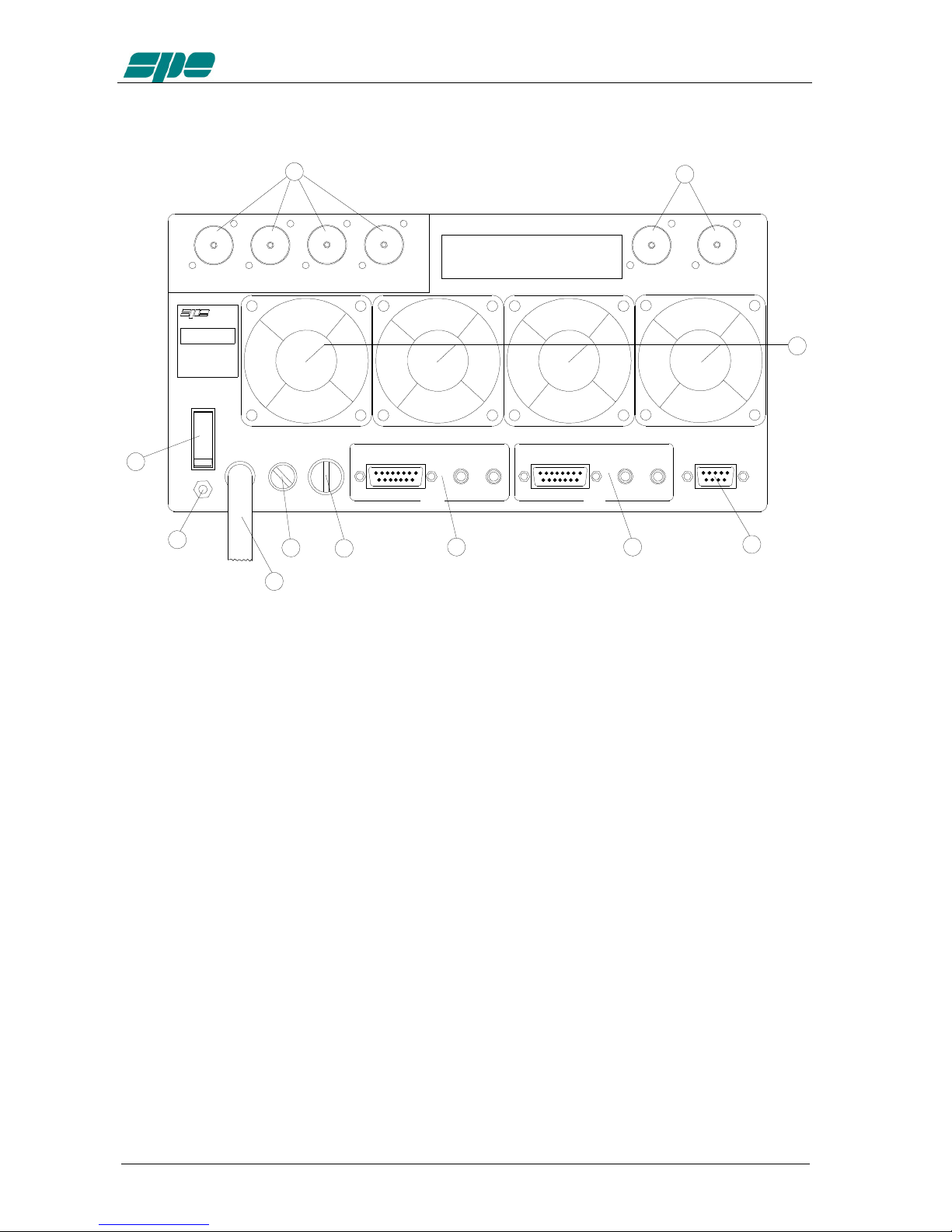
1.2 Rear Panel
ANT 1
ANT 1ANT 1
ANT 1
FUSE 2
FUSE 2FUSE 2
FUSE 2FUSE 1
FUSE 1FUSE 1
FUSE 1AC
ACAC
AC
IN 1
IN 1IN 1
IN 1
RELAY
RELAYRELAY
RELAYCAT
CATCAT
CAT ALC
ALCALC
ALC CAT
CATCAT
CAT ALC
ALCALC
ALCRELAY
RELAYRELAY
RELAY RS232
RS232RS232
RS232
ON
ONON
ON
WARNING
WARNINGWARNING
WARNING
I
II
I
O
OO
O
ANT 2
ANT 2ANT 2
ANT 2 ANT 4
ANT 4ANT 4
ANT 4ANT 3
ANT 3ANT 3
ANT 3 INPUT 1
INPUT 1INPUT 1
INPUT 1 INPUT 2
INPUT 2INPUT 2
INPUT 2
IN 2
IN 2IN 2
IN 2
1
11
12
22
2
4
44
4
6
66
65
55
5
7
77
7
8
88
8
11
1111
11
9
99
9
10
1010
10
- NE ER disconnect any antenna dunring transmittion
- NE ER disconnect any antenna dunring transmittion- NE ER disconnect any antenna dunring transmittion
- NE ER disconnect any antenna dunring transmittion
- NE ER apply AC voltage until the amplifier is grounded
- NE ER apply AC voltage until the amplifier is grounded- NE ER apply AC voltage until the amplifier is grounded
- NE ER apply AC voltage until the amplifier is grounded
- NE ER remove the cabinet with AC cable connected
- NE ER remove the cabinet with AC cable connected- NE ER remove the cabinet with AC cable connected
- NE ER remove the cabinet with AC cable connected
3
33
3
1) ANT connectors for four possible antennas.
2) INPUT connectors to connect two exciters.
3) FANS
4) RS 232 CONNECTOR
5) IN 1 ALC, RELAY, CAT connectors for exciter 1.
6) IN 2 ALC, RELAY, CAT connectors for exciter 2.
7) FUSE 2 fuse for the power supply; PA unit 12.5A (230 Vac), 20A (115 Vac).
8) FUSE 1 fuse for the power supply; electronic unit 0.5A ( 230 Vac ),
1A (115 Vac ).
9) AC mains power cable.
10) GND ground connector.
11) ON main switch.

User’s manual EXPERT 1K-FA
Pag. 9 of 42
2. GENERAL INFORMATION
(Read the specific chapters for more details).
2.1 Power supply
The amplifier’s power supply is 230 / 115 Vac (230 Vac default).
The main switch [I/O] is located on the rear panel, in the [O] position all the internal
circuitry is powered off, in the [I] position (red led ON) it is possibile turn ON or turn OFF
the linear amplifier in one of the following ways:
a) Using the [ON] /[ OFF] keys on the front panel.
b) Applying / removing 9 -15 Vdc on pin (8) of the CAT connector.
c) Using the RS232 port and the management software. It is possible to
download this software from the website www.linear-amplifier.com .
NOTE: When turned ON, almost all transceivers output 13,8 Vdc. With this voltage, the linear
amplifier can be turned automatically ON / OFF at the same time as the transceiver.
2.2 Input / Output
The linear amplifier has two inputs (INPUT 1, INPUT 2) to which it is possible to connect
two transceivers of any brand or type. These inputs are selected with the [INPUT] key.
It can manage up to four antennas (ANT 1, ANT 2, ANT 3, ANT 4).
The amplifier selects antennas automatically when they have been programmed.
2.3 ALC / RELAY / CAT
There are two transceiver inputs (IN 1, IN 2), to allow two different transceivers to be
connected at the same time.
ALC Is a voltage (0, -11 Vcc) generated by the amplifier, it is used to control the
output power of the transceiver. In this way the power from the amplifier may
be automatically controlled. This link is recommended.
If the ALC port is not connected, it is ncessary to manually regulate the drive
power from the transceiver.
RELAY This essential link allows the amplifier to be put in the transmit state. To do
that it is necessary that the inner pin of the phono connector is connected to
signal ground. This is normally done at the transceiver with either a close on
ground relay, or with a switching transistor. It is important that the voltages at
that terminal do not exceed 12 Vdc. On the transceiver this link is often called
SEND or TX GND. Refer to your transceiver manual for more details.
CAT Thanks to this link the linear amplifier will detect the operating frequency of
the transceiver and then automatically control changes of band, antenna and
automatic antenna tuner. Most modern tranceivers have CAT control. In old
models often, analog or digital information are sent for changing band. The
SPE Expert 1K-FA, thanks to an efficient frequency counter, constantly
controls and verifies data coming from the transceiver. Automatic
management of bands, antennas and tuner can be done in the following way:

User’s manual EXPERT 1K-FA
Pag. 10 of 42
a) In recent ICOM, YAESU, KENWOOD models, through CAT.
b) In the older ICOM models, through “Band Control Voltage”.
c) In the YAESU models not listed, or without CAT, through "Band
Data".
d) In every other case through the frequency counter.
NOTE: In case d) the CAT link with the transceiver is not needed because the
frequency is detected from the transmitted signal.

User’s manual EXPERT 1K-FA
Pag. 11 of 42
3. INTERCONNECTION WITH THE TRANSCEIVER
ANT 1
ANT 1ANT 1
ANT 1
FUSE 2
FUSE 2FUSE 2
FUSE 2FUSE 1
FUSE 1FUSE 1
FUSE 1AC
ACAC
AC RELAY
RELAYRELAY
RELAYCAT
CATCAT
CAT ALC
ALCALC
ALC CAT
CATCAT
CAT ALC
ALCALC
ALCRELAY
RELAYRELAY
RELAY RS232
RS232RS232
RS232
ON
ONON
ON
WARNING
WARNINGWARNING
WARNING
I
II
I
O
OO
O
ANT 2
ANT 2ANT 2
ANT 2 ANT 4
ANT 4ANT 4
ANT 4ANT 3
ANT 3ANT 3
ANT 3 INPUT 1
INPUT 1INPUT 1
INPUT 1 INPUT 2
INPUT 2INPUT 2
INPUT 2
ALC
ALCALC
ALC RELAY
RELAYRELAY
RELAY GND
GNDGND
GND
TRANSCIE ER
TRANSCIE ERTRANSCIE ER
TRANSCIE ER
GND
GNDGND
GND
IN 2
IN 2IN 2
IN 2 1
1 1
1
- NE ER disconnect any antenna dunring transmittion
- NE ER disconnect any antenna dunring transmittion- NE ER disconnect any antenna dunring transmittion
- NE ER disconnect any antenna dunring transmittion
- NE ER apply AC voltage until the amplifier is grounded
- NE ER apply AC voltage until the amplifier is grounded- NE ER apply AC voltage until the amplifier is grounded
- NE ER apply AC voltage until the amplifier is grounded
- NE ER remove the cabinet with AC cable connected
- NE ER remove the cabinet with AC cable connected- NE ER remove the cabinet with AC cable connected
- NE ER remove the cabinet with AC cable connected
CAT
CATCAT
CAT
SEE MANUAL
SEE MANUALSEE MANUAL
SEE MANUAL
ANTENNAS
ANTENNASANTENNAS
ANTENNAS
The diagram shows the connections with one transceiver only.To connect the second
transceiver repeat the same connections using the port “IN 2“.
For the ALC, RELAY connections, use the shielded cable (furnished) with phono RCA
connectors.
For the CAT connection, the cable must be made for the transceiver to be connected.
This cable may also be made to include ALC, RELAY ON / OFF (read the “CAT
Connections“ chapter of this manual).
For all other information about connecting a transceiver, please refer to its manual.
User’s manual EXPERT 1K-FA
Pag. 12 of 42
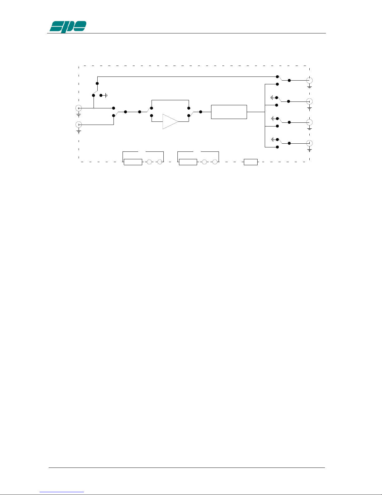
4. USE OF THE LINEAR AMPLIFIER
TUNER
ANT 1
ANT 2
ANT 3
ANT 4
INPUT 1
INPUT 2
AMPLIFIER
ALC RS 232CAT RELAY ALCCAT RELAY
IN 1 IN 2
The position of the contacts, as shown in the diagram, is the situation of the linear
amplifier in OFF state.
The linear amplifier can be used in the following ways:
1) OFF Only direct connection between INPUT 1 and ANT 1 exists.
2) STANDBY All the functions are activated (band change, antenna change, tuner
control) but the transmission is from the transceiver only.
3) OPERATE All the functions are activated and the transmission is using the
linear amplifier.
NOTE: Regulation of the exciter’s power is automatic through the ALC connection (the
maximum power in STANDBY, the neeted power in OPERATE).
Without the connection, you have to manually regulate the exciter’s power..
NOTE: For continuous duty cycle transmissions (RTTY, PSKxx, SSTV, FM, AM etc.) we
recommend switching the power to “HALF“ state.

User’s manual EXPERT 1K-FA
Pag. 13 of 42
5. EXTERNAL GROUND CONNECTION
WARNING! Before connecting an external ground as described below, check
with a qualified electrician that your national wiring codes permit such a
connection.
To reduce TVI, BCI and other RF problems it is sometimes helpful to connect the
amplifier to a good RF ground.
The inductance of such a connection has to be low, so the connection to ground should
be as short and direct as possible. Large-section copper conductors should be used for
this purpose. Terminating the earth connection with a small metal plate is suggested.
The best solution is to have a ground stake, driven into the ground, and used only for
the radio station.
Often good results can be acheived using correct earthing clamps, connected to the
mains water supply pipe (attention, most water pipes are now in plastic).
DO NOT use central heating pipework.
AVOID the electric circuit ground of the building ( to be used for the 50/60 Hz safety
only ).
WARNING! DO NOT connect to gas pipes because there is danger of explosion !!
6. ANTENNA
Because this is a high-power amplifier, it is necessary to use correctly-rated antennas
and feedline cables.
Take special care with antennas with traps, because trap warming can occur during
periods of high-power transmission and a high SWR can result.
Always use antennas with SWR less than 1,6:1, even if the tuner is able to overcome
some mismatches greater than 3:1.
With the tuner the PA is matched, but with a high VSWR, the cable is mismatched and
there can be consequent loss of power, heating and high voltages present.
It is suggested that suitable static protection be given to antenna feeder cables.

User’s manual EXPERT 1K-FA
Pag. 14 of 42
7. POWER SUPPLY
The power supply unit of the SPE Expert 1K-FA has two blocks with two separate
power transformers.
The first block has regulated and protected voltages, and powers all the electronic
circuits for command and control.
The second block powers only the PA. It has a toroidal transformer with a low magnetic
field to avoid disturbances to nearby equipment. The output voltages are 44 Vdc (on
Full-power mode) and 30 Vdc (on Half-power mode), regulated with SCRs that also
provide ‘soft start’ on switch-on.
This design was adopted as it provides maximum efficiency and therefore less heat to
dissipate.
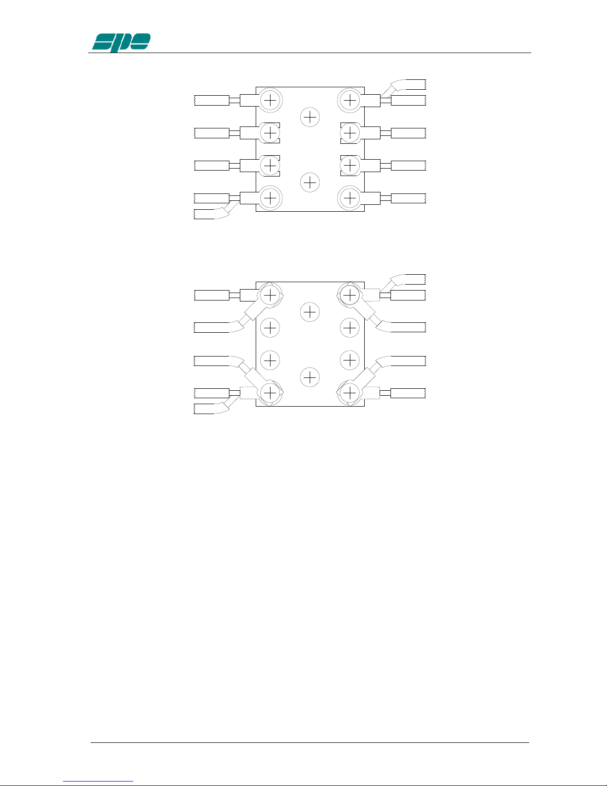
7.1 Mains cable termination
Your dealer will ensure that a mains plug appropriate for the country of use is fitted.
If the amplifier is used in a country other than that of the original purchase, refer to your
dealer for assistance.
The default mains voltage supply of the amplifier is 230 Vac (210-250Vac).
To change this to 115 Vac (105-125 Vac). (USA customers and other countries with 115
Vac supplies) see below:
WARNING! -
REMOVE THE MAINS CORD FROM THE WALL SOCKET AND
WAIT AT LEAST 2 MINUTES FOR CAPACITORS TO DISCHARGE.
Only then, remove the bottom cover, the plastic protection and connect following the
diagrams below:
blue (white)
green/yellow (green)
brown (black)
The green / yellow wire from AC power cable must be
connected to the ground wire.
The blue and brown wires from the AC power cable
can be connected to either terminal.
The green / yellow wire from AC power cable must be
connected to the ground wire.
The blue wire from AC power cable must be
connected to the hot (live) wire.
The brown wire from AC power cable must be
connected to the return wire.
Single-phase 3-wire line (210-250 VAC)
Single-phase 2-wire line (105-125 VAC)
blue (white)
green/yellow (green)
brown (black)
User’s manual EXPERT 1K-FA
Pag. 15 of 42
50 W
TRANSFORMER
1 KW
TRANSFORMER
230 VAC
brown brown
brown
whitewhite
blackblack
blue
blue
blue
115 VAC
1 KW
TRANSFORMER 50 W
TRANSFORMER
brown
brown
brown
whitewhite
black
black
blueblue
blue
After checking your wiring, re-install the plastic protection, the bottom cover and make
sure that in “Fuse 1” there is a 1A fuse and in “Fuse 2” there is a 20A fuse (included in
the packaging). Mark the change of voltage on the back panel.

User’s manual EXPERT 1K-FA
Pag. 16 of 42
8. TUNER
The amplifier has an automatic tuner that handles load mismatches up to 3:1 VSWR
(2,5:1 for 50 MHz).
The circuit used is a PI – L network with excellent harmonic suppression.
The amplifier contains a look-up table with all the permitted bands.
For tuner management, antenna data and other working data are stored.
Every band has a sub-band set, and for each of those, data related to the antenna and
auto-ATU tuning is stored.
The CAT and the frequency counter detect the operating frequency and the correct
sub-band. Thanks to the stored data, the tuner and the antenna are automatically set
correctly.
For every input there is a different table. If two exciters are connected at the same time,
each exciter can have different configurations.
It is possible to use the two different tables when the amplifier operates at two different
locations. In fact it is possible to use the INPUT 1 at one and INPUT 2 on the other. In
this way repeated reprogrammings are not needed
In the US version, operation on the 12 m and 10 m bands has been inhibited following
FCC regulations. Authorized 12/10m operation of the amplifier by licensed radio
amateurs will be enabled by the dealer there in accordance with current rules.
The auto-tuner and antenna selection via the amplifier are still enabled even in 12/10m
inhibited units.
All auto-tuner functions remain, on standby, whilst using the transceiver only.
Setting of the match data to write in the tables is performed automatically by pressing
the [TUNE] key The system will then find the correct match for minimum SWR.
To achieve a better match than that achieved with the automatic tune routine (most
unlikely) it is possible to set the tuning manually by using the keys [◄C], [C ►], [◄L],
[L ►].
When manual tuning has been performed, it is possible to read the tuning value, the
working frequency and the associated sub-band on the appropriate screen page.
Both the types of tuning are always effected in “STANDBY“ state.
NOTE: The tuner, like all analog circuits, introduces a loss (0,8 dB max.) that may vary with
tuning conditions.The power meter of the amplifier does not show this loss as the
power is measured at the tuner input where the load resistance is always constant
(50 ohm).
NOTE: ATTENTION, When the amplifier is on the ‘STANDBY’ or ‘OPERATE’ modes, always
disable the automatic tuner in your transceiver.

User’s manual EXPERT 1K-FA
Pag. 17 of 42
9. PROTECTIONS / ALARMS
The SPE 1K-FA has a sophisticated protection system that constantly controls the
amplifier’s most important parameters.
These parameters are:
Temperature of the heatsink; max. / min. voltage on the PA; max. PA current; SWR;
reflected power; max voltage RF on the tuner; input power; power combiner balance.
NOTE: Unlike all the other linear amplifiers that measure only the reflected power of the
antenna, to guarantee a greater protection of the PA, the SPE amplifier measures also
the power of harmonics reflected by the band-pass filter.
NOTE: To guarantee the maximum efficiency with the same output power, the PA has three
MRF150 push-pull amplifiers connected through a combiner.
NOTE: Temperature measurement is used also to control fan speed. The thresholds where the
speed changes may be changed from NORMAL (default) or CONTEST (See the
“Programming” chapter of this manual).
The protection system is effected in two different ways:
1) Through hardware circuits to guarantee minimum intervention time.
2) Through software, with one of the two CPU’s, to guarantee the maximum
precision.
The two results are always compared, every difference produces a protection trip and
consequent alarm.
There are three types of protections/alarms:
a) SIMPLE This is the most common case. An acoustic warning beep
sounds, but no operator intervention is required, as the control
system automatically restores the correct operating conditions.
b) SERIOUS When automatic system recovery is not possible (e.g. the
temperature climbs over the limits due to obstruction of the fans,
SWR is too high, etc.). In this case the amplifier switches into
standby state and the alarm is stored. Normally transmission can
continue with the exciter only.
c) FATAL If the amplifier is in the b) situation but the CPU is faulty or it isn’t
able to operate, the amplifier is turned OFF with no other
warning. To restart the amplifier, the main switch in the rear
panel has to be set first to [O], and then to the [I] position
NOTE: It is possibile to read the alarms file log in the standby state using the [DISPLAY] key.
To reset the alarm file log press the [TUNE] and [OPERATE] keys together.
NOTE: If the acoustic alarm is very frequent during transmission, the possible causes should
be investigated.

User’s manual EXPERT 1K-FA
Pag. 18 of 42
NOTE: Before the temperature limits are reached, the output power will change from FULL
to HALF automatically, so that transmission with the amplifier may continue with
reduced power.
In SSB the use of the compressor, only when necessary, strongly reduces the
increase of the temperature.
If the temperature is allowed to rise further, then a “SERIOUS“ alarm will eventually
be activated.
NOTE: During a SERIOUS alarm, there is an acoustic alarm for 30 sec. Pressing the
[DISPLAY] key, the system changes to ‘STANDBY’ state immediately.
User’s manual EXPERT 1K-FA
Pag. 19 of 42
10. PROGRAMMING
The three [SET], [◄▲] and [►▼] keys, underlined with an orange line, permit
programing the amplifier and they can used in the following way:
[SET] Use it to open the menu page, to validate the choices and to exit from
the menu page.
[◄▲], [►▼] Use these to select the options.
A green led illuminates during the programming process.
To program the system is very easy. You will find your programming choices confirmed
by the items shown at the lower part of the display.
NOTE: Programming is only possible in ‘STANDBY’ mode.
NOTE: Programming changes take effect only after exiting from the menu page (the green led
extinguishes).
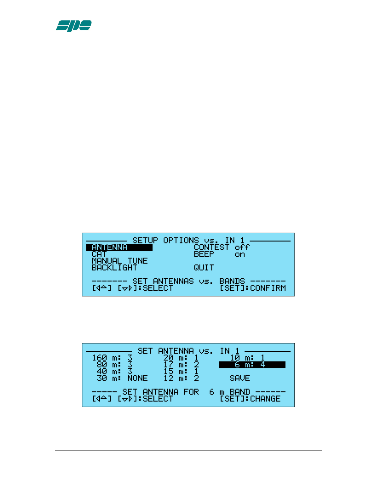
10.1 Ways to operate
Pressing the [SET] key opens the menu page. On the display there are the following
options:
a) ANTENNA An appropriate antenna may be assigned to each band selecting
the (ANT 1, ANT 2, ANT 3, ANT 4) connector.
If you don’t have an antenna for a particular band, input “NONE“.

User’s manual EXPERT 1K-FA
Pag. 20 of 42
b) CAT Allows you to program the amplifier to accept control commands from
specific transceiver types.
You may need to refer to your transceiver user manual to ensure that
it is correctly programmed to handle such a link.
Select the brand or function:
- SPE No further programming is necessary, all is already
programmed for the SPE transceivers.
- ICOM You need to choose between “CI-V“, or “Band Control
Voltage “ if you use the analog connection (read the “CAT
CONNECTION” chapter of this manual).
If you choose “CI-V“, you also need to choose the baud rate
which is usually 9600.
- KENWOOD You have to choose the baud rate (almost always 9600).
-YAESU If you use the CAT connection (read the “CAT
CONNECTION” chapter of this manual), select the model of
the transceiver and than select the baud rate (almost always
4800). If the model isn’t in the list, select “Band Data“ (read
the “CAT CONNECTION” chapter of this manual).
- RS232 With a proper protocol it is possible to use this port not only
as a remote control but also as a CAT port (useful to link the
linear with any customer application).
Download the protocol specification from the website
www.linear-amplifier.com
- NONE Program when there isn’t a link with the Transceiver.
The amplifier frequency counter will then be used .
NOTE: If using the CAT, check that the baud rate of your transceiver is set to the same value as
you program to the amplifier.
Other manuals for EXPERT 1K-FA
2
Table of contents
Other SPE Amplifier manuals


