Spica SERVO User manual

id363182953 pdfMachine by Broadgun Software - a great PDF writer! - a great PDF creator! - http://www.pdfmachine.com http://www.broadgun.com
INTRODUCTION
Your
new
SPICA
SERVO
subwoofer
is
designed
to
extend
the
low
frequency
performance
of
the
SPICA
TC-50
speaker
system.
Its
computer-optimized
crossover
network,
servo
error
correction
circuit,
specially
designed
S"
woofer,
and
internal
70
watt
power
amplifier
all
contribute
to
give
a
dramatic
improvement
in
your
system's
clarity
and
definition,
while
allowing
higher
sound
pressure
levels
to
be
obtained.
And
it
does
all
of
this
without
degrading
the
superior
stereo
imaging
that
the
TC-50
is
famous
for.
We
are
confident
that
you
will
be
more
than
pleased
with
this
addition
to
your
system.
An
important
consideration
in
the
design
of
the
SERVO
was
to
make
it
flexible
enough
to
be used
with
whatever
rec.iver
or
power
amplifier
you
might
be
using
for
your TC-50s,
while
retaining
the
sonic
purity
that
your
system
already
has.
To
accomplish
this,
a
simple
passive
filter
is
used
in
the
portion
of
the
crossover
network
that
feeds
the
TC-50s.
This
part
of
the
setup
procedure
represents
aminor
inconvenience
for
you,
the
end
user.
Although
the
procedure
is
asomewhat
technical
one,
we
have
made
every
effort
to
present
it
as
simply
as
possible.
Please
read
and
follow
the
instructions
carefully.
Some
of
the
'tools'
you
>
CASSETTE
PLAYER
>
MEASURING
TAPE
>
SOLDERING
IRON
will
need
are:
(for
setting
levels)
(for
physical
placement)
(for
capacitor
installation)
For
setting
the
relative
level
of
the
subwoofer
with
greater
accuracy,
a
method
is
provided
that
requires
the
use
of
an
AC
VOLTMETER.
If
you
do
not have
a
soldering
iron,
your
SPICA
dealer
will
be
able
to
assist
you
in
installing
the
capacitors
into
the
passive
box.
We
mentioned above
that
the
SERVO
does
not
degrade
the
stereo
imaging
abilities
of
the
TC-50. Another
way
of
saying
this
is
that
the
SERVO
is
a
phase-
coherent
addition
to
the
TC-50.
This
is
quite
a
distinction
from
all
of
the
'generic'
subwoofers
available
which,
by
their
very
nature,
can
only
give
'generic'
results.
If
by
chance
you
are
using
the
SERVO
with
satellite
speakers
other
than
the
TC-50,
we
have
no
way
of
predicting
how
sucessfully
the
SERVO
will
match
up
with
them, and
the
setup
procedures
given
in
this
manual
may
not
be
applicable
to
your
system.
We
would
like
to
acknowledge
the
fine
folks
at
PS
AUDIO
for
the
design
of
the
internal
70
watt
power
amplifier
and
the
servo
circuit.
CHECKING
SYSTEM
POLARITY
Suppose
you
were
standing
in
front
of
a
mirror
that
turned
everything
reflected
in
it
upside
down. All
the
features
of
the
image would be
there,
but
they
would be
inverted.
This
is
a
visual
analogy
of what
is
called
POLARITY.
The
audio
industry
has
not
established
any
polarity
standards,
so
some
pieces
of
equipment
invert
the
signal
as
it
passes
through
them, and
others
do
not.
In
order
to
determine
the
polarity
of your
system,
you
must
find
out
which
pieces
in
your
system
invert
the
signal,
and which
ones
do
not.
This
information
is
often
given
in
the
owner's
manual of
each
piece.
If
it
is
not,
contact
your
dealer
or
the
manufacturer
to
find
this
out
now.
2
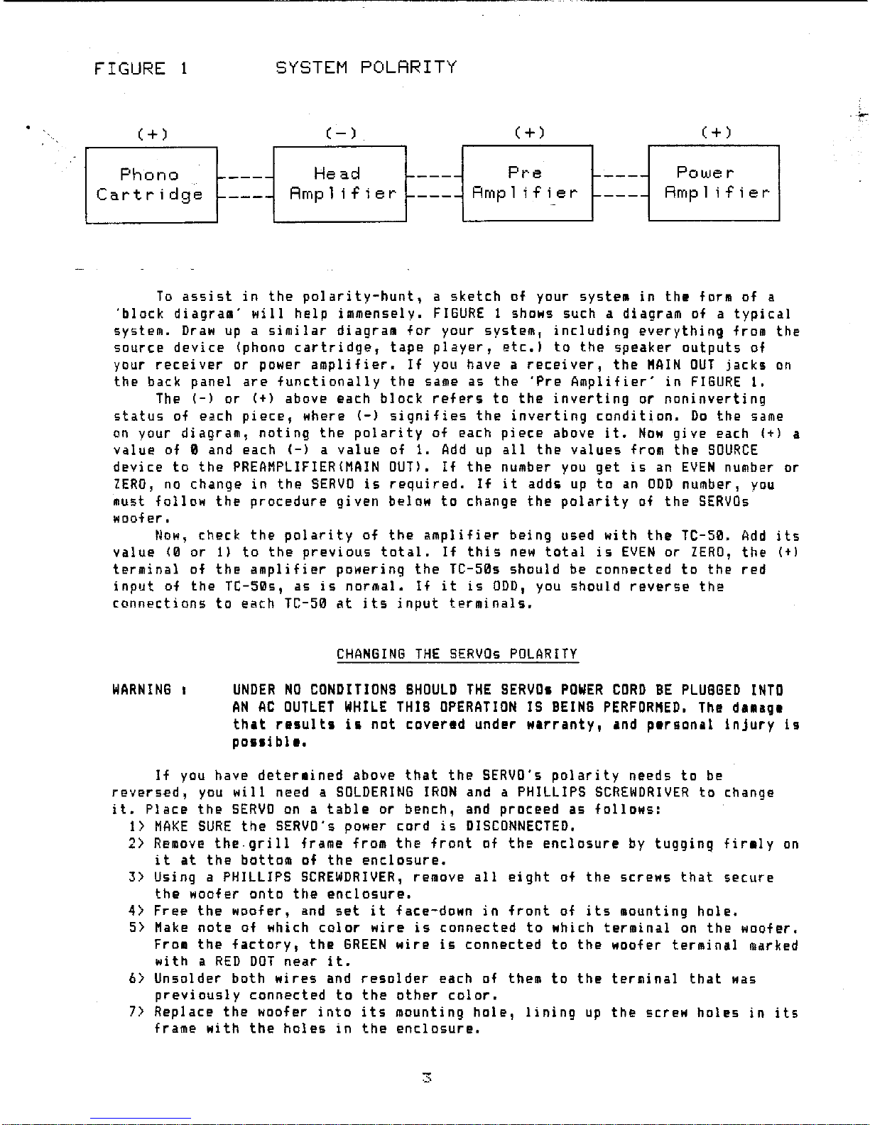
FIGURE 1
SYSTEM
POLRRITY
;..-
(+
)
(-)
(+
)
(+
)
Phono
-----
Head
'-----
Pre
f-----
Powe r
Cartridge
-----
Rmp
1; f ; e r ,...----
Rmp
1
if
i e r
f-----
Rmpl
ifier
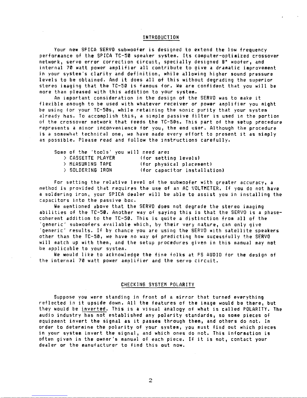
To
assist
in
the
polarity-hunt,
a
sketch
of
your
system
in
the
form of a
'block
diagram'
will
help
immensely.
FIGURE
1shows such adiagram of a
typical
system.
Draw
up
a
similar
diagram
for
your
system,
including
everything
from
the
source
device
(phono
cartridge,
tape
player,
etc.)
to
the
speaker
outputs
of
your
receiver
or power
amplifier.
If
you have a
receiver,
the
"AIN
OUT
jacks
on
the
back
panel
are
functionally
the
same
as
the
'Pre
Amplifier'
in
FIGURE
I,
The
(-)
or
(+)
above
each
block
refers
to
the
inverting
or
noninverting
status
of each
piece,
where
(-)
signifies
the
inverting
condition.
Do
the
same
on
your
diagram,
noting
the
polarity
of
each
piece
above
it.
Now
give
each
(+)
a
value
of 0and each
(-)
a
value
of
1.
Add
up
all
the
values
from
the
SOURCE
device
to
the
PREAMPLIFIER(MAIN
OUT).
If
the
number
you
get
is
an
EVEN
number or
ZERO,
no
change
in
the
SERVO
is
requi
red.
If
it
adds
up
to
an
ODD
number I
you
must
follow
the
procedure
given
below
to
change
the
polarity
of
the
SERVOs
woofer.
Now,
check
the
polarity
of
the
amplifier
being
used
with
the
TC-50.
Add
its
value
(0
or
I)
to
the
previous
total.
If
this
new
total
is
EVEN
or
ZERO,
the
(t)
terminal
of
the
amplifier
powering
the
TC-50s
should
be
connected
to
the
red
input
of
the
TC-50s,
as
is
normal.
If
it
is
ODD,
you
should
reverse
the
connections
to
each
TC-50
at
its
input
terminals.
CHANGING
THE
SERVOs
POLARITY
WARNING
I
UNDER
NO
CONDITIONS
SHOULD
THE
SERVOs
POWER
CORD
BE
PLUGGED
INTO
AN
AC
OUTLET
WHILE
THIS
OPERATION
IS
BEING
PERFOR"ED.
The
damagl
that
results
is
not
covered
under
warranty,
and
plrsonal
injury
Is
poui
bIt.
If
you have
determined
above
that
the
SERVO's
polarity
needs
to
be
reversed,
you
will
need a
SOLDERING
IRON
and aPHILLIPS
SCREWDRIVER
to
change
it.
Place
the
SERVO
on
a
table
or
bench,
and
proceed
as
follows:
1>
MAKE
SURE
the
SERVO's
power
cord
is
DISCONNECTED.
2>
Remove
the.grill
frame from
the
front
of
the
enclosure
by
tugging
firmly
on
it
at
the
bottom of
the
enclosure.
3>
Using aPHILLIPS
SCREWDRIVER,
remove
all
eight
of
the
screws
that
secure
the
woofer
onto
the
enclosure.
4>
Free
the
woofer,
and
set
it
face-down
in
front
of
its
mounting
hole.
5>
Make
note
of which
color
wire
is
connected
to
which
terminal
on
the
woofer.
From
the
factory,
the
GREEN
wire
is
connected
to
the
woofer
terminal
marked
with
a
RED
DOT
near
it.
6>
Unsolder
both
wires
and
resolder
each of them
to
the
terminal
that
was
previously
connected
to
the
other
color.
7>
Replace
the
woofer
into
its
mounting
hole,
lining
up
the
screw
holes
in
its
frame
with
the
holes
in
the
enclosure.
=
Capacitor
value
lin
microfarads}
~
8)
Screw each
screw
in
part
way, making
sure
the
woofer
is
seated
evenly
all
around,
then
tighten
them
up
in
a
cross-wise
fashion.
DO
NOT
overtighten
them,
or
the
holes
will
strip.
They
should
be
firmly
snug.
9)
Replace
the
grill
frame
onto
the
enclosure,
pushing
around
the
perimeter
to
engage
the
Velcro
fasteners.
10)
VOILA
'!
PASSIVE
INTERFACE
SETUP
To
interface
properly
with
the
SERVO,
the
signal
sent
to
the
amplifier
that
is
driving
the
TC-50s must be
'high
pass
filtered'
at
the
correct
frequency,
This
is
accomplished
by
installing
the
proper
value
of
capacitor
into
the
PASSIVE
INTERFACE
box.
The
value
of
this
capacitor
is
determined
by
the
input
impedance of
the
power
amp
you
are
using.
If
you
are
using
a
receiver
to
power
the
TC-50s,
it
must have Preamp Out!
Main
Amp
In
jacks
on
the
rear
panel.
If
yours
does
not,
you
should
contact
your
dealer
to
make
the
appropriate
modifica-
tions
to
your
unit.
Find
out
the
input
impedance
of
your
amplifier
unit,
This
information
is
normally
given
in
the
owner's
manual;
if
it
is
not,
your
dealer
can
find
it
out
for
you.
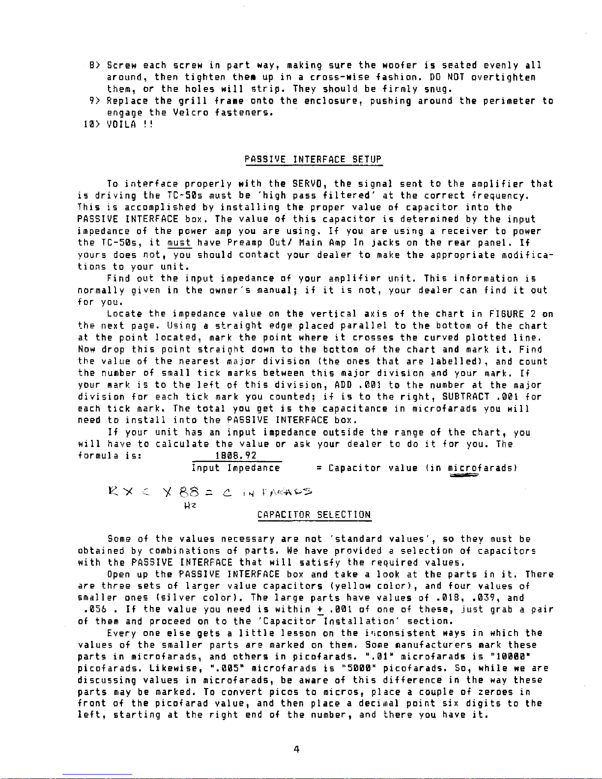
Locate
the
impedance
value
on
the
vertical
axis
of
the
chart
in
FIGURE
2
on
the
next
page.
Using a
straight
edge
placed
parallel
to
the
bottom
of
the
chart
at
the
point
located,
mark
the
point
where
it
crosses
the
curved
plotted
line.
Now
drop
this
point
straight
down
to
the
bottom of
the
chart
and mark
it.
Find
the
value
of
the
nearest
major
division
(the
ones
that
are
labelled),
and
count
the
number of
small
tick
marks between
this
major
division
and your mark.
If
your
mark
is
to
the
left
of
this
division,
ADD
.001
to
the
number
at
the
major
division
for
each
tick
mark you
counted;
if
is
to
the
right,
SU8TRACT
.001
for
each
tick
mark. The
total
you
get
is
the
capacitance
in
microfarads
you
will
need
to
install
into
the
PASSIVE
INTERFACE
box.
If
your
unit
has
an
input
impedance
outside
the
range
of
the
chart,
you
will
have
to
calculate
the
value
or ask your
dealer
to
do
it
for
you.
The
formula
is:
1808.92
Input
Impedance
CAPACITOR
SELECTION
Some
of
the
values
necessary
are
not
'standard
values',
so
they
must be
obtained
by
combinations
of
parts.
We
have
provided
a
selection
of
capacitors
with
the
PASSIVE
INTERFACE
that
will
satisfy
the
required
values.
Open
up
the
PASSIVE
INTERFACE
box
and
take
a
look
at
the
parts
in
it.
There
are
three
sets
of
larger
value
capacitors
(yellow
color),
and
four
values
of
smaller
ones
(silver
colorl.
The
large
parts
have
values
of
.018, .039,
and
.056
.
If
the
value
you
need
is
within
~
.001
of
one of
these,
just
grab a
pair
of them and
proceed
on
to
the
'Capacitor
Installation'
section.
Everyone
else
gets
a
little
lesson
on
the
inconsistent
ways
in
which
the
values
of
the
smaller
parts
are
marked
on
them.
Some
manufacturers
mark
these
parts
in
microfarads,
and
others
in
picofarads.
".01"
microfarads
is
"10000'
picofarads.
Likewise,
".005"
microfarads
is
"5000"
picofarads.
So,
while
we
are
discussing
values
in
microfarads,
be aware of
this
difference
in
the
way
these
parts
may
be marked.
To
convert
picas
to
micros,
place
a
couple
of
zeroes
in
front
of
the
picofarad
value,
and
then
place
a
decimal
point
six
digits
to
the
left,
starting
at
the
right
end of
the
number, and
there
you have
it.
4
PASSIVE INTERFACE CRPRCITOR
CHART
.018
.025
.076 .068
.061
.054 .047
.040
.032
CAPACITOR
VALUE
(Microfarads)
.083
40k
50k
30k
90k
70k
60k
80k
100k
.--------,----...,.---,.----,----.,-.
--...,.---,.----,----,.---
......
·
·
·
·
·
• _
••
-
__
-
_.
_~
.0
•••••
~
•••••••••••
~
_
••
_.
_._.
_.l-
••
_.
-
_0
_.
_.:-
••••••••••
~
•••••••••••
.;
••••
__
._
•••
.;
•••••
0.
__
•
_,_.
__
•
_.
__
•
:: : ::: : ::
, • I , • • • , I
:: : :: : :::
• • I , • • • , •
,,,. . . . ,.
: : : : :: : ::
••••••••
_.
_:
••
_. _. _.
:-_
- _
••••••••
:-
••••••••
-0
_:-
••
"0
__
:-
••
__
•
-:
__
•
••
-:_.
_.
•
-:
__
••
_0.
_
•••
~
••
_
• • , • • I • • ,
•
..
, I • I • • •
• • I • • I I , ,
·.,. . ,..,
:::::: : ::
: : : : : : : : .
._
•••••
- : - •
__
.~_
- _
••••••••
~.
00
0 • _.~
••
_.
•
~
•
_. _.
~
•
_. _.
__
~.
_.
_
••
_
•••
_
~_
•••••••••
~
__
••
_
••
•
: : : : : : : : :
, • I • • I • , •
:::::::
~:
:
:::::::::
• • I • , , • , I
•••••••
-
•••
~
--
_.
--
_.
--
-:-
--
_.
-
_.
_.
-
-:-
•••••••••
_.:-. --
•••
-.
--
-l-
-
-.
-
_. _. _.
~
••-
-.-.
--
_.
-:.
_.
-
-.-.
-
••
-:...
..""
••
-
~.
_.
-
_. _.
_.-
:: : :: : :: :
:::: :
::
:
,., , ,
..
,
:::: :
::
:
:::: : : : .:
...--_-
_.
_.
---_---_..-_----
_.
-_--
_.
---
_.
_
_.
-
_.
-
_.
_
_. _.
---_
_....
..
-_------
_.
-
_.
-
_.
-.-.
-.
, , , ... . ,,
:: : : : : : ::
: : : :
::
::
::::
::
::
_
..
_
..
_.
_
..
~.
_
..
_
t.
._.
__
.
_t
__
.
_. _. _.
_.t
..
_".
_. _.
_
.t
..
_."
_.
-_.
J.
_. _.
_
.;.
_. _.
--
_. _.
J_
-.'
_""
-1_
..
_.
__
.
: : :
::
::
,,.
.'
.,
:::
::
::
:: :
:,
::
,... . . . .,
_
....
_
..
_
..
~
....
_······r····
-.
-.-
--r·
_. _.
-
-_.
_. _.
-
_.
--
-
·r-·
-_
...
--
'1"'·
_. _. _.
·-1·
_.
_
..
-
_.
-
·1····
-
--_.
--1-·
--
--."
_
..
"
"."
"
".,.
:'
:::::
·, , ..,
,.::::
2
0k
L,.,,~:::t::~_e.L.
............
.o._J.
.............
'_'_'_~~..L.......J....L...L..J.l.......ww...J....L...:....
J....l.."'-'w....c.J.~-'--W...L.
~..e-J
.090
w
u
z
a:::
Q
W
ll..
~
H
(/)
E
.!:
o
.::L
I-
::J
ll..
Z
H
Okay' A
calculator
will
come
in
handy
now.
From
the
three
larger
parts,
select
the
value
that
is
less
than
the
value
you
need.
Subtract
it
from
the
total.
Then
find
the
nearest
value
that
is
less
than
or
equal
to
this
remainder.
Do
this
until
you
are
within
.002
of
the
value
you
need.
The
nearer
the
better,
but
this
accuracy
is
sufficient.
If
your
amp's
input
iapedance
is
60K
Ohms
or
greate"
get
within
.001
of
the
target
value.
CAPACITOR
INSTALLATION
Its
time
to
fire
up
your
soldering
iron.
You
will
find
a
length
of
solder
in
the
PASSIVE
INTERFACE
box;
it's
good
stuff,
so
use
it.
If
you needed more
than
one
capacitor
to
get
your
target
value,
hold
the
smaller
parts
length-wise
along
the
larger
part,
and
BENTLY
wrap
the
lead
of each
smaller
part
a
couple
of
turns
around
that
of
the
I
arger
at
each
end. The
leads
of
the
small
si
I
ver
parts
are
a
little
fragile,
so
don·t
tug
on
thea
too
hard.
You
will
do
this
twice,
once
for
each
channel.
Do
yourself
a
favor,
and
double
check your
work
before
you
solder.
You
should
have two
capacitor
clusters
with
identical
parts
in
each.
5
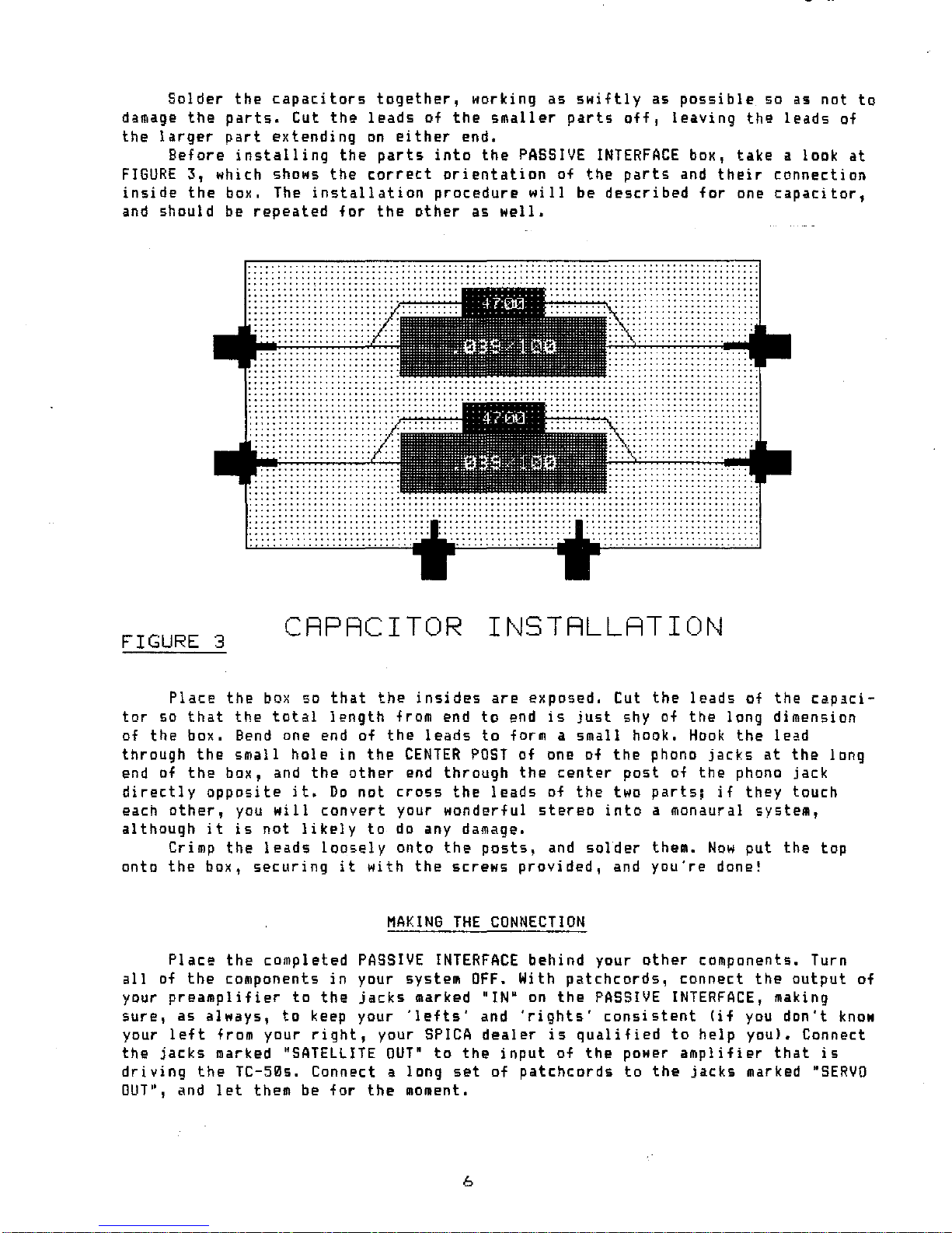
Solder
the
capacitors
together,
working
as
swiftly
as
possible
so
as
not
to
damage
the
parts.
Cut
the
leads
of
the
smaller
parts
off
I
leaving
the
leads
of
the
larger
part
extending
on
either
end.
Before
installing
the
parts
into
the
PASSIVE
INTERFACE
box,
take
alook
at
FIGURE
3,
which shows
the
correct
orientation
of
the
parts
and
their
connection
inside
the
box. The
installation
procedure
will
be
described
for
one
capacitor,
and
should
be
repeated
for
the
other
as
well
•
.......................................................................................
......................................................................................
.......
.
............................................
..
.••.....................................
.........................
/'".
,.,.,.,..,.,.,.,..,.
..
-.
..
...........
.......................... ..
.........................................................................
.
.........................................................................
.
.........................................................................
.
......................................................................... .
..................
............................
FIGURE 3
CAPACITOR
INSTALLATION
Place
the
box
so
that
the
insides
aro
exposed.
Cut
the
leads
of
the
capaci-
tor
so
that
the
total
length
from end
to
end
is
just
shy of
the
long
dimension
of
tho
box.
Bend
one end of
the
leads
to
form a
small
hook.
Hook
the
load
through
the
small
hole
in
the
CENTER
POST
of one of
the
phono
jacks
at
the
long
end of
the
box,
and
the
other
end
through
the
center
post
of
the
phono
jack
directly
opposite
it.
Do
not
cross
the
leads
of
the
two
parts;
if
they
touch
each
other,
you
will
convert
your
wonderful
stereo
into
amonaural
system,
although
it
is
not
likely
to
do
any damage.
Crimp
the
leads
loosely
onto
the
posts,
and
solder
them.
Now
put
the
top
onto
the
box,
securing
it
with
the
screws
provided,
and
you're
done!
MAKING
THE
CONNECTION
Place
the
completed
PASSIVE
INTERFACE
behind
your
other
components. Turn
all
of
the
components
in
your
system
OFF.
With
patchcords,
connect
the
output
of
your
preamplifier
to
the
jackS
marked "IN"
on
the
PASSIVE
INTERFACE,
making
sure,
as
always,
to
keep your
'lefts'
and
'rights'
consistent
(if
you
don't
know
your
left
from
your
right,
your
SPICA
dealer
is
qualifiod
to
help
you).
Connect
the
jacks
marked
"SATELLITE
OUT'
to
the
input
of
the
power
amplifier
that
is
driving
the
TC-50s. Connect a
long
set
of
patchcords
to
the
jacks
marked
·SERVO
OUT",
and
let
them be
for
the
moment.
6

PLACEMENT
In
phase-coherent
systems
(as
in
life
in
general),
TIMIN6
IS
OF
THE
ESSENCE.
In
order
that
the
timing
relationships
of
the
SERVO
and
the
TC-50s be
correct,
it
is
necessary
that
the
distance
from
the
SERVO
to
your
listening
position
be
greater
than
the
distance
from
the
TC-50s
to
your
listening
position
by
a
certain
amount.
If
this
is
not
done,
all
of
the
other
system
parameters
will
be thrown
out
of whack.
Also,
where
you
place
the
SERVO(s)
depends
on
whether you
are
using
one
or
two of them
in
your
system.
Fortunately,
this
is
a
very
simple
procedure.
All you need
is
a
MEASURIN6
TAPE,
and
possibly
a
helper.
FOR
SIN6LE
SERVO
SYSTEMS:
As
shown
in
FI6URE
4,
the
SERVO
should
be
placed
in
between
the
TC-50s.
Placing
it
anywhere
else
in
your
room
will
result
in
reduced
accuracy,
because
the
SERVO
must be
placed
at
a
fixed
distance
offset
from each TC-50.
And
since
one
SERVO
is
serving
this
function
for
two TC-50s,
placing
it
in
between
the
TC-50s
is
the
only
way
this
condition
can be
satisfied
•
,
,
FIGURE 4
,
,
SINGLE
•I
I
I
I
I
I
I
•
SERVO PLRCEMENT
7

FOR
DUAL
SERVO
SYSTEMS:
As
shown
in
FIGURE
5,
the
SERVOs
should
be
placed
as
closely
as
possible
to
each TC-50. Having them
on
the
outside
is
slightly
preferable,
but
the
inside
is
fine.
For optimum
performance,
you
may
want
to
consider
using
the
stands
which
have been
specifically
designed
for
the
TC-50
when
used
with
dual
SERVOs.
They
are
made
by
Chicago
Speaker
Stand.
These
stands
mount
on
top
of
the
SERVO
enclosure,
placing
the
TC-50
at
the
correct
distance
offset,
and can accomodate
a
range
of
listening
heights
through
their
tilt
adjustment.
Ask
your
dealer
for
more
information.
/
/
.
.
/
I
I
/
/
I
"'-.
'',- \/
,/
/
"'-.'\\
//
~:
\\\\
\
,,,
,.,
,,
FIGURE
5
DURL
SERVO
PLRCEMENT
ALL
SYSTEMS:
1>
Put a
small
piece
of masking
tape
on
the
couch
or
chair
you
listen
in,
at
a
point
near
where your head
is
located
when
you
are
seated.
2>
Use your
measuring
tape
to
find
the
distance
from
this
point
to
the
BOTTOM
FRONT
EDGE
of one of
the
TC-50s, and
write
it
down.
3>
Now
measure
the
distance
to
the
other
TC-50 from
the
same
point,
and
move
it
backward
or
forward
until
the
two
distances
are
identical.
4>
Place
the
SERVO(s)
in
the
location
described
above,
at
a
distance
that
is
4.5
inches
GREATER
than
the
TC-50s,
as
measured from
the
same
point
to
the
BOTTOM
FRONT
EDGE
of
the
SERVO(s).
8
5>
Plug
the
patch
cords
from
the
PASSIVE
INTERFACE
into
the
SERVO
Is).
If
you
are
using
one
SERVO,
it
makes
no
difference
which
cord
is
plugged
into
which
jack.
If
you
are
using
two,
check
to
make
sure
your
lefts
and
rights
are
consistent
with
the
rest
of
the
system,
but
don't
use
the
furnished
shorting
plug
until
we
find
out
later
whether
you
need
to
or
not.
6>
Plug
the
pDwer
cord
Df
the
SERVO(s)
into
an
AC
Dutlet.
OON'T
turn
it
on
just
yet.
SETTING
LEVELS
It
is
nDt
uncommDn
these
days
for
people
leven
non-hobbyist
types)
to
have
an
AC
Voltmeter
around
the
hDuse.
or
at
least
tD
have a
friend
that
does.
If
YDU
do,
here's
an
DppDrtunity
to
put
it
tD
gDDd
use.
On
the
back
panel
Df
the
SERVO
is
a
level
contrDl.
It
is
used
to
set
the
lDudness
Df
the
SERVO
to
the
prDper
level.
There
is
sufficient
gain
(12
dB)
in
this
cDntrDl
tD
match
the
sensitivity
Df
almost
any
amplifier
you
may
be
using
tD
drive
the
TC-50s. There
is
alsD enough
gain
here
SD
that
if
the
cDntrDl
has
inadvertantly
been
'cranked
up',
SDme
damage
could
be
dDne
tD
the
amplifier
Dr
wDofer
in
the
SERVO.
Turn
the
control
tD
its
fullv
counter-clDckwise
positiDn.
We
are
prDviding
two
methods
Df
setting
levels;
one
is
strictly
subjective,
the
Dther
is
empirical.
If
YDU
have
access
to
a
vDltmeter,
we
strDngly
suggest
YDU
use
the
empirical
methDd;
why
guess
if
you
dDn't
have
to?
Both methods
require
the
use
of a
CASSETTE
PLAYER;
the
quality
of
the
unit
is
not
important.
The
level
setting
procedure
takes
advantage
Df
the
following
fact,
AT
ONE
FREQUENCY,
THE
ACOUSTIC
OUTPUT
OF
THE
SERVO
AND
THE
TC-50
ARE
THE
SAME.
We
have
furnished
a
cassette
that
has
five
minutes
of
this
frequency
recorded
on
each
side
of
it.
If
you
are
going
to
follow
the
SUBJECTIVE
METHOO,
a
friendly
assistant
would be
helpful.
BOTH
METHODS,
1>
Connect a
cassette
player
tD
the
apprDpriate
inputs
of your
system.
2>
Turn
the
level
contrDl
on
your preamp
or
receiver
all
the
way
down.
3>
Set
your Bass and
Treble
controls
to
their
center
(off)
positions.
They
should
remain
off
for
the
entire
setup
procedure.
4>
Turn
all
of
the
cDmponents
in
your
system
ON,
except
the
SERVOls).
5>
Place
the
SERVO
SETUP
cassette
into
your
player.
SUBJECTIVE
METHOD,
This
method
requires
a
little
bit
of
explanation
before
we
jump
right
into
it.
You
will
be
listening
to
the
tone
recorded
on
the
SERVO
SETUP
tape,
first
played
through
the
TC-50s
alone,
then
through
the
SERVO
Is)
alone.
You
therefore
need
SDme
way
of
disabling
the
output
to
the
TC-50s
when
listening
to
the
tone
through
the
SERVO.
To
accomplish
this;
>
If
YDU
have a
separate
power
amplifier
for
the
TC-50s,
all
you have
to
do
is
turn
that
unit
off.
>
If
you
have a
receiver
or
integrated
amplifier
that
has
speaker
switching,
all
you have
to
do
is
switch
the
speaker
selector
to
off
or
to
the
other
DUtpUt.
>
If
you
have none of
these,
you must
turn
the
receiver
off
lwithout
changing
the
level
control
on
it),
disconnect
the
patch
cords
from
the
Passive
Interface
Box
to
the
receiver
main
input,
then
turn
the
unit
back on.
Whichever
is
appropriate
for
your
case,
it
is
referred
to
in
the
instruc-
tions
that
follow
as
"disabling
the
TC-50s".
If
you
are
using
a
DUAL
SERVO
setup,
the
instructions
given
should
be
repeated
for
each
side.
Use
your
balance
control
to
get
the
tone
output
from
the
side
that
the
setup
is
being
done
for.
During
the
setup,
if
you
should
find
that
9
the
SERVO
level
control
is
turned
all
the
way
down
and
is
still
too
loud,
then
insert
a
shorting
plug
into
the
unused
input,
and
start
the
level
procedure
again.
This
will
give
an
additional
b
dB
of
attenuation.
If
you
are
using
a
SINGLE
SERVO
setup,
place
your
balance
control
in
the
center
position.
Do
not
change
it
during
the
setup
procedure.
5)
Start
the
cassette
running.
and
set
the
level
to
a
comfortable
one,
using
your
preamp/receiver's
level
control.
Do
not
change
the
setting
of
this
control
during
the
setup
procedure.
b>
Disable
the
SERVO
by
turning
its
power
switch
to
OFF.
7)
From
your
listening
location.
listen
to
the
loudness
of
the
tone
that
comes
through
the
TC-50s
alone.
8>
Disable
the
TC-50s, and
turn
the
SERVO
power
switch
to
ON.
9>
Listen
to
the
loudness
of
the
tone
from
the
SERVO
alone.
and
adjust
the
SERVO
level
control
until
it
is
the
same
as
it
was
from
the
TC-50s.
If
there
is
any
doubt.
set
the
SERVO
level
on
the
low
side.
10>
Repeat
steps
b
through
9
until
you
are
satisfied
that
the
levels
from
the
TC-50s and
the
SERVO
are
the
same.
11) For dual
SERVO
setups,
turn
your
balance
control
to
the
opposite
side.
and
start
at
step
b
again.
12>
Skip
to
the
section
on
'Some
Fine
Points'.
EMPIRICAL
METHOD:
This
is
the
easiest
and most
accurate
method. Making
sure
not
to
move
the
SERVO
from
its
optimum
location.
remove
the
grill
frame from
the
SERVO.
Above
the
woofer.
to
the
left,
flush
with
the
face
of
the
enclosure.
are
two exposed
Test
Points.
Before
we
proceed,
a
word
of
caution
is
in
order.
These
Test
Points
are
connected
DIRECTLY
to
the
power
amplifier,
and
are
also
part
of
the
SERVO's
'comparator',
If
they
are
accidentally
shorted
together.
connected
to
an
AC
ground.
or
if
any
voltages
are
applied
to
these
test
points,
you
stand
a
good
chance
of
'blowing
up'
the
power
amplifier
in
the
SERVO.
Before
measuring
the
voltages
at
these
Test
Points:
)
YOUR
VOLTMETER
MUST
BE
SET
TO
MEASURE
AC
VOLTS.
If
it
is
set
on
the
Resis-
tance
mode.
it
will
insert
a
reference
voltage
into
the
SERVO
circuit,
and
most
assuredly
will
cause
some
damage.
>
YOUR
VOLTMETER
MUST
NOT
BE
CONNECTED
TO
AN
AC
OUTLET.
but
should
be
operating
on
its
internal
batteries.
If
EITHER
test
point
is
connected
to
an
AC
GROUND.
the
SERVO
will
go
up
in
smoke
before
your
very
eyes.
If
you
have a
SINGLE
SERVO
system.
turn
your
balance
control
all
the
way
to
one
side
or
the
other,
and
start
at
step
b.
5>
Set
the
balance
control
on
your
preamp/receiver
to
its
center
position.
b>
Turn
the
SERVO(s)
power
switch
on.
7)
Start
the
cassette
running.
and
set
the
level
to
a
comfortable
one,
using
your
preamp/receiver's
level
control.
Do
not
change
the
setting
of
this
control
during
the
setup
procedure.
8>
Measure
the
voltage
at
the
input
terminals
of
the
TC-50, and
write
it
down.
9>
MULTIPLY
this
figure
times
~
.
10)
Hook
the
voltmeter
to
the
Test
Points
on
the
SERVO.
11>
Adjust
the
SERVO
level
control
until
the
voltage
measures
the
same
as
the
figure
obtained
in
Step
9.
12>
For
DUAL
SERVO
systems.
repeat
Steps
B
through
11
for
the
other
channel.
13)
Replace
the
grill
frame
onto
the
enclosure,
pushing
around
the
perimeter
of
it
to
engage
the
Velcro.
14>
Th-th-that's
all,
folks'
10
SOME
FINE
POINTS
Before
going
on
further
with
this,
take
some
time
now
and
listen
to
some
music
through
your
new
system.
Listen
to
a
variety
of
material,
and
notice
how
different
the
character
of
the
low
frequency
part
of
the
music
is
as
you
go
from
one
recording
to
another.
Then
come
back,
and
we'll
go
through
some
fine
points
regarding
the
setup.
If
you're
pleased
as
punch
with
your
system,
and
can't
imagine
that
it
could
be any
better,
then
you're
all
done and you need
not
concern
yourself
with
this
section
on
fine
tuning
your
system.
If
you'd
like
to
extract
the
last
ounce
of
accuracy
out
of
it,
and you
don't
mind
a
little
'tech
talk',
then
read
on.
There
are
two
factors
that
can
affect
the
absolute
accuracy
of
the
setup
procedure
you've
just
completed.
The
first
factor
is
a
combination
of al
the
distances
from
the
SERVO
and your
listening
position
to
the
various
surfaces
in
your room, and bl
the
'liveness'
or
'deadness'
of
the
floor
immediately
in
front
of
the
SERVO,
which can be
'tuned'
by
fine
changes
in
the
placement
of
the
SERVO.
The
second
factor
is
variations
in
the
sensitivities
of
the
drivers
in
both
the
TC-50 and
the
SERVO,
which can be
'tuned'
by
adjustments
to
the
SERVO
level
control.
This
is
what
we
call
OPTIMIZING,
a
procedure
that
is
avery
meaningful one
for
us
here
at
SPICA.
It
is
distinguished
from
IDEALIZING
in
that
it
takes
into
consideration
the
immutable
'undesirable'
conditions
as
well
as
the
desirable
ones
in
any
circumstance.
The
very
walls
in
your
room
are
one such
undesirable
condition,
in
that
they
restrict
the
free
expansion
of
the
sound
pressure
wave, and
create
resonances
and
cancellations
at
frequencies
that
are
related
to
the
distances
between
these
surfaces.
This
is
actually
a
very
complex
subject,
but
the
long
and
short
of
it
is
that
your
listening
position
may
be
placed
in
a
location
where
there
is
a
strong
'buildup'
or
cancellation
of
acoustical
energy.
and
this
may
be
happening
right
in
the
frequency
range
where
the
SERVO
and
the
TC-50s
are
trying
to
combine
their
contributions
to
the
overall
sound.
If
the
distance
from
the
SERVO
to
the
wall
behind
it
is
identical
to
the
distance
from your
listening
position
to
the
wall
behind
it,
you
are
most
likely
listening
in
one such
problem
area.
The
solution
is
to
make
these
distances
unequal
by
relocating
your
listening
position
or
the
TC-50s and
the
SERVO
together.
After
making any
changes
to
the
position,
remember
to
go
through
the
procedures
on
placement
again,
to
ensure
that
the
relative
distances
are
correct.
Now
lets
take
alook
at
the
effects
of
the
reflective
character
of
the
floor
in
your room.
The
SERVO
is
specifically
intended
to
be
placed
on
the
floor,
or
'floor
coupled',
as
we
call
it.
At
low
frequenties,
this
placement
effectively
eliminates
the
floor
from
being
one of
the
early
reflective
sources
that
we
mentioned
above.
At
higher
frequencies,
this
becomes
increasingly
less
true,
so
that
the
absorbtive
character
of
the
floor
immediately
in
front
of
the
SERVO
effects
the
smoothness
of
the
SERVO's
output
at
higher
frequencies,
which
in
turn
has a
subtle
(or
not-sa-subtle,
depending
on
your
attentiveness)
effect
on
the
audible
result.
We
recommend
that
a
rug
be
placed
under or
immediately
in
front
of
the
SERVO.
Hark
the
current
position
of
the
front
of
the
SERVO
on
your
floor
with
a
small
piece
of
masking
tape.
From
your
collection,
choose
some
recorded
material
that
has
either
very
coherent
depth
in
it,
or
very
percussive
low
frequency
information.
Choose a30
second
long
passage
that
'grabs
you',
and
listen
to
it
with
the
system
set
up
the
way
it
is
now.
Listen
in
particular
to
the
quality
of
the
impact
of low
frequency
transients,
to
the
'focus'
of
the
instruments
that
seem
to
come
from
further
back
in
the
soundstage,
and
to
the
general
sense
of
warmth of
the
overall
sound.
Now
experiment
with
moving
the
SERVO
back a
little
bit
from
the
original
position,
listening
to
the
same
passage
after
every
move.
11

There
~ill
be a
place
~here
the
three
above
qualities
~ill
come
together
dramatically.
If
you have gone more
than
an
inch
or
so
away
from
the
original
position,
you have gone
too
far,
and you might want
to
choose a
different
selection
of
program
material.
To
correct
for
the
variations
in
the
sensitivities
of
the
various
drivers
in
the
system,
you
can
make
minute
adjustments
to
the
SERVO
level
control,
using
the
same
criteria
as
given
above.
Be
sure
to
mark
your
original
position
before
you
start,
so
that
you can
return
to
it
for
comparisons.
Some
words
of
caution
are
in
order
here.
If
you
do
make
adjustments
to
the
SERVO
level
control,
keep
the
following
in
mind:
>
We
Americans,
as
a
culture,
tend
to
be
'bass
freaks'
~ith
our sound
systems,
so
there
is
going
to
be a
tendency
to
want
to
keep
'cranking
it
up'
in
order
to
achieve
that
indistinct·
'sameness'
in
bass
quality
that
we
have
all
grown
up
~ith.
>
You
will
find
that
continually
increasing
the
SERVOs
loudness
above
the
proper
level
actually
lessens
the
perceived
bass'
Things
start
to
cancel
each
other
rather
than
working
together.
>
DO
NOT
use
the
SERVO
level
control
as
a
bass
tone
control.
Use
your preamps
bass
control
to
compensate
for
bass-deficient
recordings.
>
The
SERVO
has
a
built
in
'rumble
filter',
We
have
purposely
set
it
at
the
extremely
low
frequency
of
4
Hertz.
If
you
are:
a)
playing
a
record
that
is
badly
warped,
b)
playing
your
system
VERY
loud,
c)
boosting
the
bass
with
your
bass
tone
control,
then
you
should
consider
engaging
the
rumble
filter
on
your preamp I
receiver
if
it
has
one.
Otherwise,
you
should
leave
it
off.
>Avoid
the
use
of
the
LOUDNESS
button
on
your
receiver.
TECHNICAL
SPECIFICATIONS
System
type
Woofer
Enclosure
Volume
System Resonance IQ
Low
Frequency
Extension
Woofer
Hipass
Crossover
Lopass
Crossover
Input
Impedance
Polarity
Level
Control
Power
Amplifier
Size
in
inches(cm)
Weight
in
Ibs(kg)
Sealed
box
1.25
cu.
ft.
31
Hz,
Total
Q
.5
-3dB @
25
Hz
B"
diameter
with
I"
peak-to-peak
excursion
Passive
1st
Order,
-3dB @
BB
Hz
Electronic
with
computer-derived
slope
110k
Ohms
open,
20k
Ohms
one
input
shorted
Inverting,
for
use
with
non-inverting
TC-50s
Continuously
variable
within
a
12dB
range
Solid
state
70
watts
RMS
minimum
17.5(44.5)W
X
14.5(3b.B)H
X
15.B75(40.3)D
:40(IB.251
WARRANTY
To
the
original
purchaser,
SPICA
warranties
the
SERVO
to
be
free
from
mechanical
defects
for
five(5}
years
and
electronic
defects
for
one(ll
year
from
the
date
of
purchase,
when
purchased
from
an
authorized
SPICA
dealer.
Your
sales
receipt
is
your
proof
of
purchase.
This
warranty
excludes
damage
caused
by
user
abuse,
carelessness,
and
modifications
other
than
those
covered
in
the
owners
manual.
SPICA
reserves
the
right
to
make
final
determination
of
warranty
coverage.
SPICA
makes
no
other
warranties,
either
expressed
or
implied.
12
Table of contents


