Spod 87-0095 User manual


2
Warranty & Returns Policy
WARRANTY AND REPAIR POLICY
sPOD oers a non-transferable 5-year limited warranty on electronic parts and components from
manufacturers defects from the date of purchase (Eecve on products purchased aer 4/1/23). sPOD will
repair or replace items in queson and return them to Buyer at no charge. If the idencal product is no
longer available, sPOD will replace with a similar product of equal value. sPOD will not be responsible for
any indirect or consequenal damages in connecon with defecve merchandise.
Exclusions:
Products that have been subjected to abuse, misuse, accident, alteraon, modicaon, improper
installaon, tampering, or any use other than the product’s designed purpose will void the warranty. The
sPOD warranty excludes the following: Installaon errors, abuse, misuse or crash damage, reverse polarity
of baery cables, changing the 2 amp fuse for any other rated fuse, cung o our connectors, splicing into
our wires/harnesses, aaching anything other than our baery cables to our posive and negave
terminal studs on our BantamX/SourceLT boards, changing our supplied switches (switch body), removing
the actuators without using our specic actuator removal tool. This warranty shall be automacally voided
if the items sent for warranty replacement are modied in any way or were not used as intended or
applicable. Addionally, this warranty excludes normal wear and tear. NOTE: Any or all aermarket brake
controllers, hi-amp solenoids or any hi-amp relay that is aached to the same posive baery post will
cause irreversible damage to the sPOD system. This will void all warranes. This warranty shall be
automacally voided if the items sent for warranty replacement are returned with water/liquid/chemical
damage to any electrical component.
The buyer MUST provide a copy of the original invoice or have completed the online product registraon.
Shipping responsibilies and/or charges will be determined once a claim has been opened. sPOD systems
will be repaired or replaced at manufacturer’s discreon. This warranty does not cover miscellaneous
expenses, including, but not limited to, outside labor costs incurred for the installaon, removal,
replacement, and repair or troubleshoong. Please contact sPOD to assist with troubleshoong prior to
uninstalling your enre system as the soluon may not require that the system be removed.
All claims must be made in wring by mail or e-mail directly to sPOD:
By Mail: sPOD 2950 Norman Strasse Road San Marcos, CA 92069
By E-mail: [email protected]

3
RETURN AND REFUND POLICY
sPOD will accept returns within 30 days from receipt of merchandise under the following condions:
Merchandise needs to be returned unused, with all printed material and accessories enclosed. If not in its
original condion or the product shows signs of installaon, addional charges will be applied or may not
be accepted. All returns must be accompanied with a return merchandise authorizaon (RMA) number (to
be provided by sPOD at me of request) and a receipt of original purchase.
To obtain an RMA number, please email Tech@4x4S-pod.com with your full name, invoice number, and
part number of the item(s) you need to return.
A 15% percent restocking fee will apply aer 30 days. All shipping charges are at the buyer’s expense. The
original shipping fees are non-refundable. We strongly recommend you insure all packages before shipping.
We are not responsible for lost or stolen merchandise while in transit. We assume liability once the
returned system has reached our facilies. Once your return shipment has been received and approved,
your return will be processed. Failure to comply with the process and terms stated above may result in a
processing delay and/or a refusal of the returned package.
The above warranes and policies are subject to change without prior noce.
4
**For a color copy of instrucons, visit your vehicle specic applicaon on BajaDesigns.com **
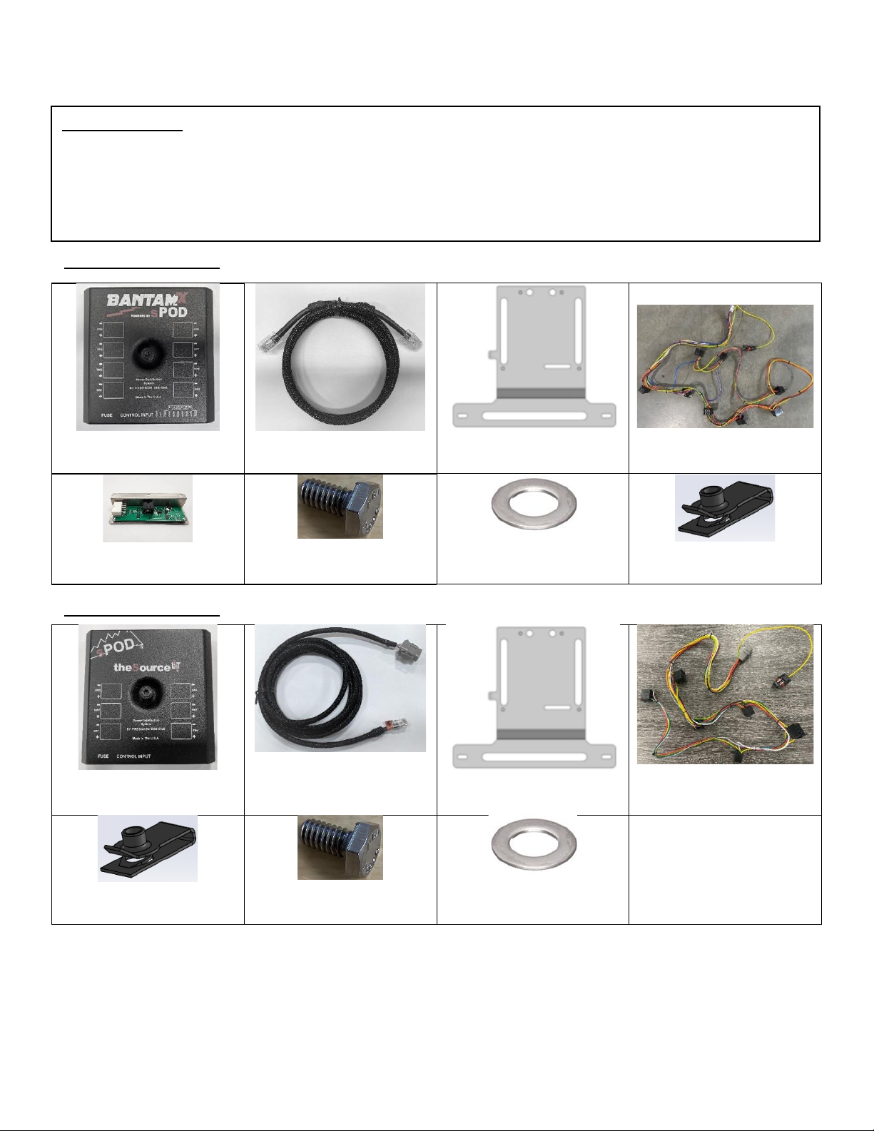
(BantamX) (Qty: 1)
BantamX w/ 84” Ba
(91-0025) (Qty: 1)
3’ Ethernet Cable
(87-0021) (Qty: 1)
PCM Bracket
(64-0307) (Qty: 1)
8-Switch Dash Harness
(CAN-Adapter) (Qty: 1)
CAN-Bus Controller
(20-1283) (Qty: 2)
¼-20x1/2” Hex Head Bolt
(20-1282) (Qty: 2)
¼ Flat Washer
(20-1278) (Qty: 2)
¼”-20 Extruded U Nut
(SourceLT) (Qty: 1)
SourceLT w/ 84” Ba
(91-0410) (Qty: 1)
Control Cable for
SourceLT
(87-0021) (Qty: 1)
PCM Bracket
(64-0306) (Qty: 1)
6-Switch Dash Harness
(20-1278) (Qty: 2)
¼”-20 Extruded U Nut
(20-1283) (Qty: 2)
¼-20x1/2” Hex Head Bolt
(20-1282) (Qty: 2)
¼ Flat Washer
Required Tool(s):
▪T20, T40 Torx
▪7/16”, 10mm wrench
▪Trim removal tool
▪Phillips head screwdriver
Parts List 8 Switch Kit:
Parts List 6 Switch Kit:
5
To begin, make sure the vehicle is in park, on level ground and the parking brake is engaged.
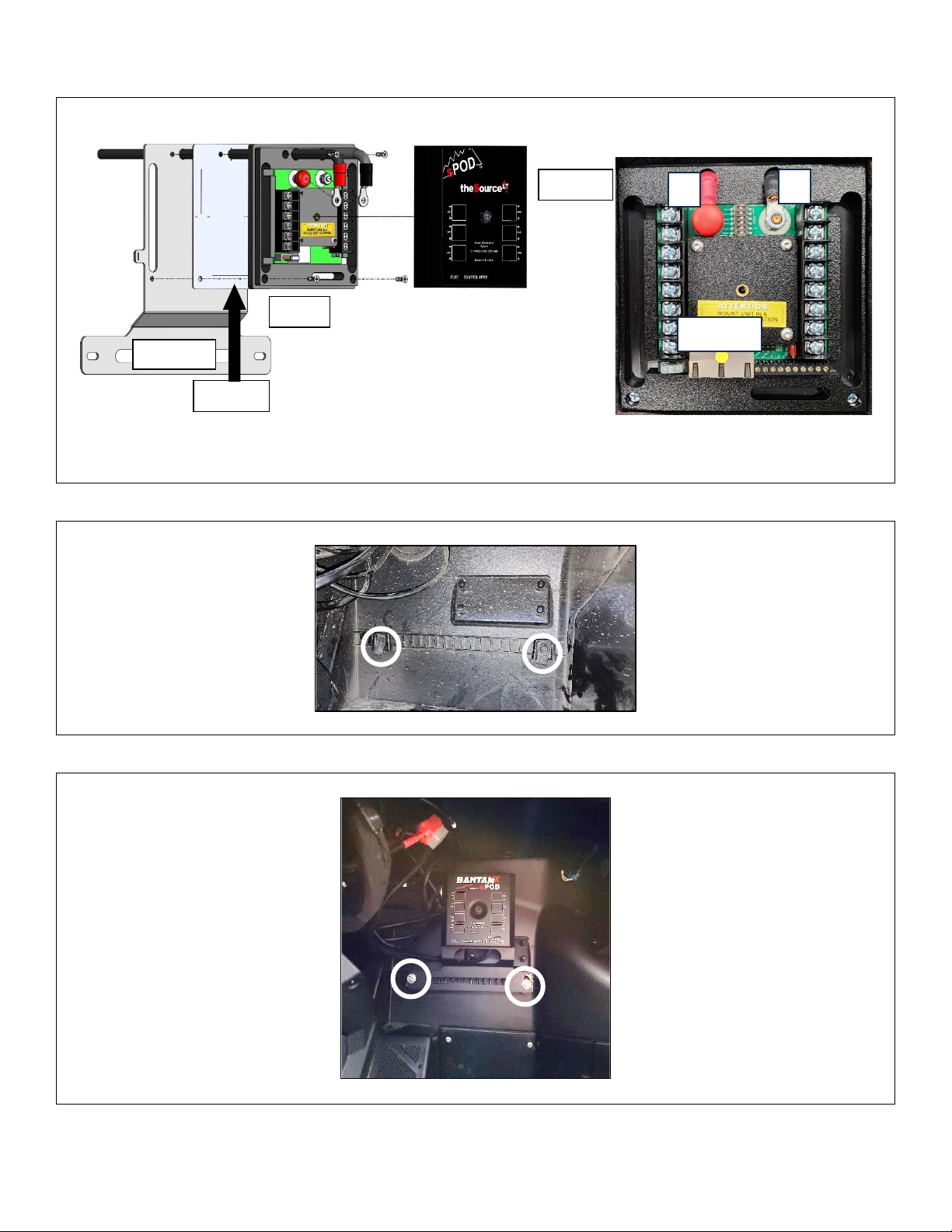
Step 1:
Remove the PCM cover. Attach the PCM to the bracket using a Phillips head screwdriver and the included
screws making sure the included gasket is in between the two. Make sure the battery cables pass through
the battery cable holes. Route the control cable in through the left slot and plug it into either port.
Step 2:
Place two included extruded u-nuts around the two tabs in the passenger footwell (circled).
Step 3:
Aach the PCM bracket to the u-nuts using the included ¼”-20 hardware and a 7/16” wrench.
Bracket
Gasket
PCM
Cover
+
-
Ethernet
6
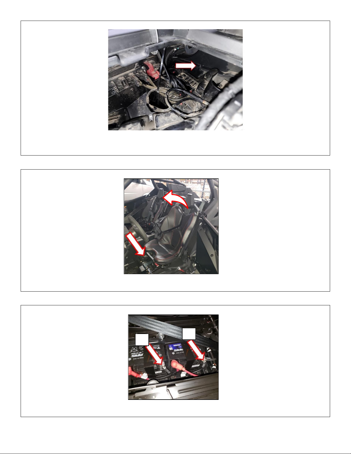
Step 4: BantamX Users only
Using a T20 Torx, remove the passenger side glove box screw (arrowed). Aach the CAN-Adapter with the
10-pin plug facing the rear of the vehicle using the rear bolt hole and the stock hardware.
Step 5:
Remove the driver and passenger seats by liing the latch located at the front of the seat and rocking
forward.
Step 6:
Using a 10mm wrench, disconnect the negave cables from the baeries. Start by disconnecng baery A’s
negave cable rst (furthest rearward baery connecon). Some models may have only one baery.
B
A
7
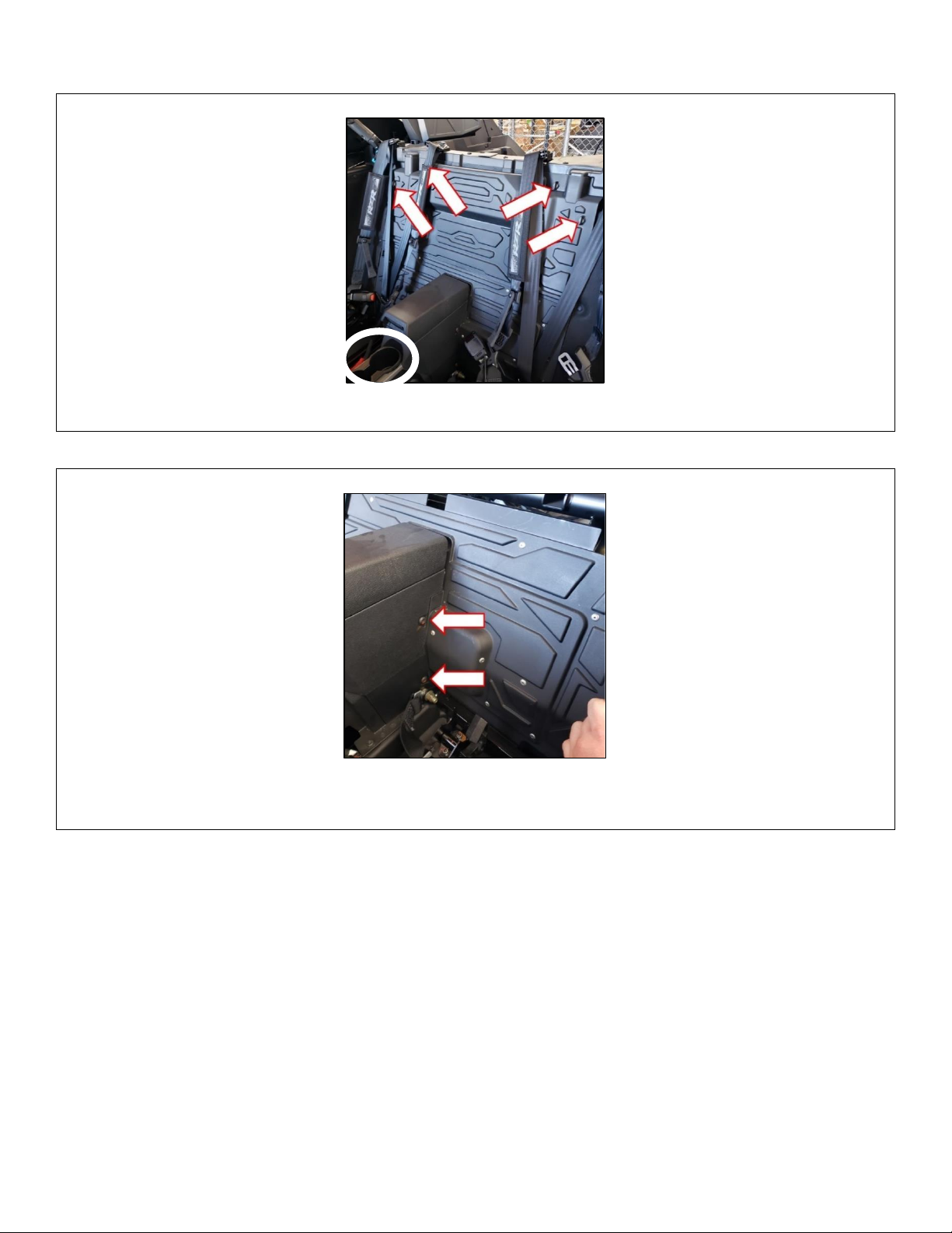
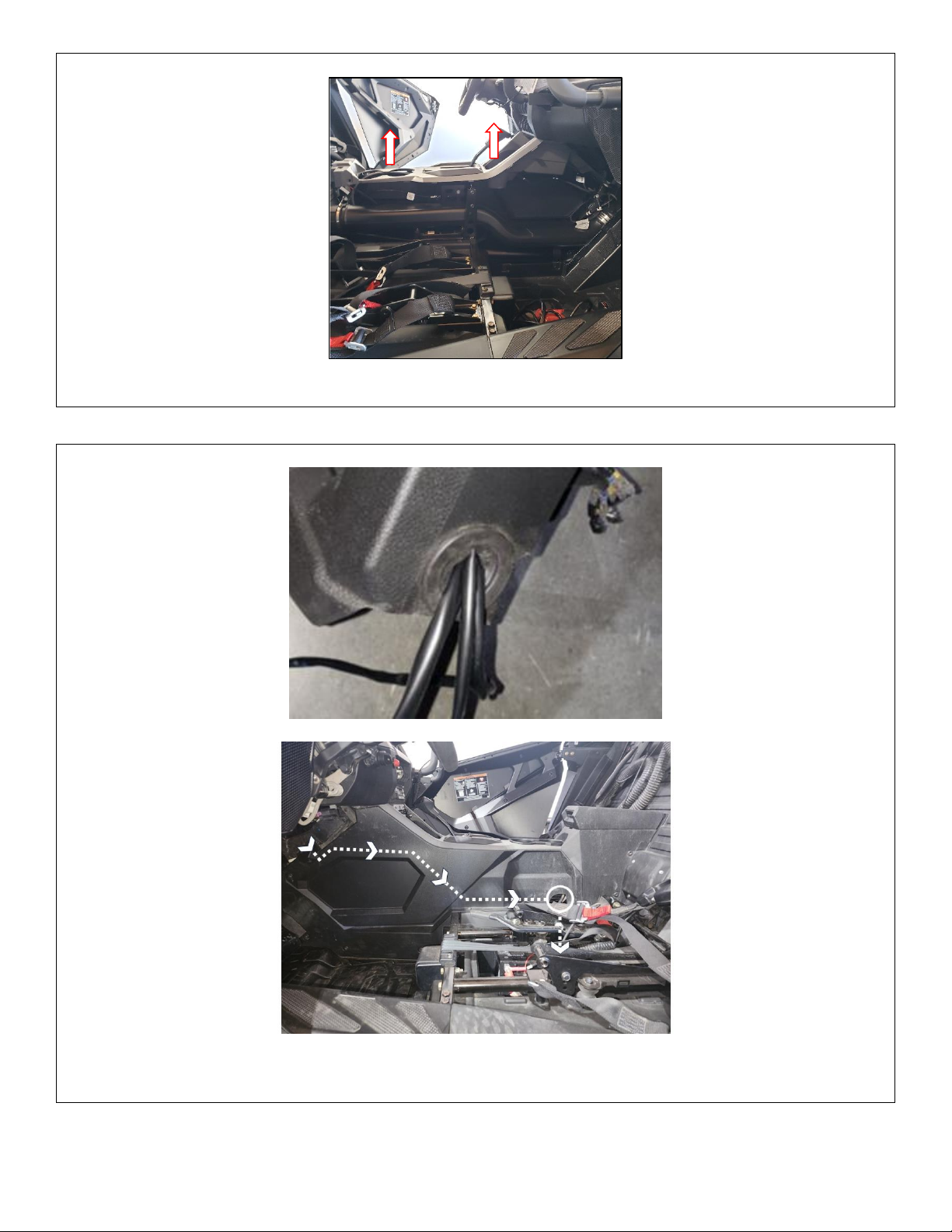
Step 7:
Remove the rear upper close-o panel by turning the 4 quarter-turn latches counter-clockwise unl they
release. Using a trim removal tool, remove the cupholder insert (circled) from the center console.
Step 8:
Using the T40 Torx, remove the 4 bolts located near the back of the center console container. Open the
center console and turn the 2 quarter-turn fasteners (located near the latch catch) clockwise unl they
release. Li up and remove the center console container assembly.

8
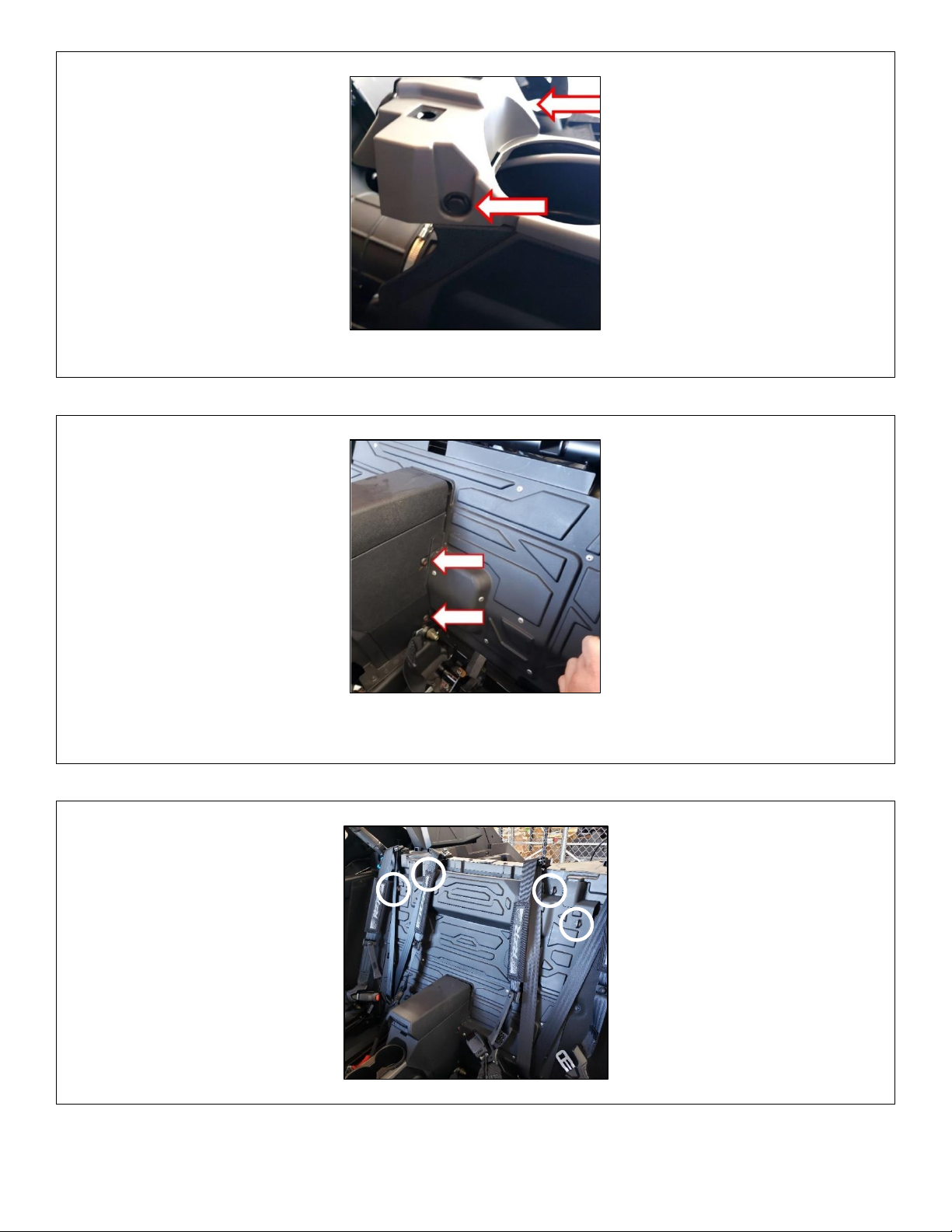
Step 9:
Using a trim removal tool or athead screwdriver, remove the 2 plasc push rivets (one side boxed) behind
the cup holders. Using a T40 Torx, remove the 8 bolts (arrowed) securing the passenger side of the center
console.
Step 10:
Locate and remove the 2 plasc push rivets on the top passenger side center console panel located under
the dash.
Step 11:
Carefully remove the LED on the passenger side center console panel by pressing the plasc trim ring back
through the panel.
9
Step 13:
Route the baery cables from the PCM through the grommet on the front of the center console panel. Run
the wires through the center console and to the baeries underneath the driver’s seat. The white circle
shows the trans tunnel access hole.
Step 12:
Carefully li upward on the center panel starng near the back to disengage the retenon tabs. Carefully
release the passenger side center console panel from the vehicle but leave it near its mounng locaon.

10
Step 14:
Using a 10mm wrench, connect the posive (red) ring terminal to the posive post of the baery. Repeat by
connecng the negave (black) ring terminal to the negave post of the baery. If you have 2 baeries.
Make sure both negave leads are connected if equipped with dual baeries.
Step 15:
Set the passenger side center console panel upright and almost into place. Plug the footwell LED into its
mounng hole. Press the panel into place making sure the PCM Power cable wires do not pinch. Insert the
two forward push rivets to hold the panel in place.
Step 16:
Reinstall the 8x T40 Torx bolts from step 9 and 2 push rivets from step 10.
11
Step 18:
Reinstall the cupholder insert unl the retenon tabs engage. Reinstall the center console compartment and
secure using the T40 Torx bolts (arrowed), 2 on each side of the console and the quarter-turn fasteners
underneath the lid. Make sure the harnesses do not become pinched between any panels.
Step 19:
Reinstall the upper block-o panel and secure using the 4 quarter-turn latches released in step 7.
Step 17:
Press the top center console panel into place making sure the retenon tabs are properly aligned. Reinstall
the push rivets located just behind the cup holders.

12
Step 20:
Reinstall the driver and passenger seats by hooking the front of the seat base and pivong them into place.
Make sure the harnesses do not become stuck behind the seats.
Step 21: For BantamX Only
Route the control cable, 10 pin wiring harness connector and Pulse Bar plug up to the CAN-Adapter. Plug the
control cable (boxed) and 10-pin connector (circled) into their respecve locaons in the CAN-Adapter.
Step 22: For SourceLT Only
Route the Deutsch connector end of the control cable to the driver side of the center console. Plug the
switch harness into the Deutsch connector of the control cable.
Pulse Bar

13
Step 23:
Press out the number of switch blanks corresponding to your sPOD unit. 6 for SourceLT’s and 8 for
BantamX’s. To enable ignion triggered backlighng, plug the Pulse Bar connector of the switch harness into
an open Pulse Bar posion. The Pulse Bar is underneath the dash console box (see step 21). See Appendix 1
for detailed harness breakdown.
Step 24:
Route the rocker switch connectors to their corresponding posions. Connect the rocker switches and press
them into posion.
*Tie all wires away from sharp, hot, and/or rotang components.
* Re-torque all the fasteners aer 100 miles.
*Your install is now complete! Thank you for choosing sPOD.

14
Appendix 1
BantamX Harness
SourceLT Harness
This manual suits for next models
7
Table of contents


