Sprite Electronics SAM-8300D User manual

SAM-8300D/8800D/6500D
Built in Digital Decoder with 5.1CH Home Theatre Speaker System
Owner's Manual
Thank you for purchasing Sprite Electronics Speaker Systems.
Please read this manual carefully and save it with your original sales receipt
for warranty services.
This product could be modified for quality improvement without notice.
This production manual uses 3 products of SAM-8300D,8800D,6500D simultaneously.
Sprite Electronics USA Inc.
www.spriteusa.com
270Esna Park Dr. Unit 2 Markham ON L3R 1H3 CANADA
W
O
R
E
P
W
E
O
R
P
I
N
T
P
U
SAM-8300D
SAM-8800D SAM-6500D
1. Read these instructions.
2. Keep these instructions.
3. Heed all warnings.
4. Follow all instructions.
5. Do not use this apparatusnear water.
6. Clean only with dry cloth.
7. Do not block any ventilation openings. Install in accordance with the manufacturer's instructions.
8. Do not install near any heat sources such as radiators, heat registers, stoves, or other apparatus
(including amplifiers) that produce heat.
9. Do not defeat the safety purpose of the polarized or grounding-type plug. A polarized plug has two blades
with one wider than the other. A grounding type plug has two blades and a third grounding prong.
The wide blade or the third prong are provided for your safety. If the provided plug does not fit into your
outlet. Consult an electrician for replacement of the obsolete outlet.
10. Protect the power cord from being walked on or pinched particularly at plugs, convenience receptacles,
and the point where they exit from the apparatus.
11. Only use attachments/accessories specified by the manufacturer.
12. Use only with the cart, stand, tripod, bracket, or table specified by the manufacturer,
or sold with the apparatus. When a cart is used, use caution when moving
the cart/apparatus combination to avoid injury from tip-over.
13. Unplug this apparatus during lightning storms or when unused for long periods of time.
14. Refer all servicing to qualified service personnel. Servicing is required when the apparatus has been
damaged in any way, such as power-supply cord or plug is damaged, liquid has been moisture, does not
operate normally, or has been dropped.
15. The apparatus shall not be exposed to dripping or splashing and that no objects filled with liquid, such as
vases, shall be placed on the apparatus.
IMPORTANT SAFETY INSTRUCTIONS
This symbol is intended to alert the user to the presence of uninsulated "Dangerous Voltage"
within the products enclosurethat may be of sufficient magnitude to constitute a risk of
electric shock to persons.
This symbol is intended to alert the user to the presence of important operating and
maintenance (servicing) instructions in the literature accompanying the appliance.
These CAUTION marks are located on the rear panel of your subwoofer.
WARNING : To reduce the risk of fire or electric shock, do not expose the system to rain or moisture.
No naked flame sources, such as lighted candles, should be placed on the appartus.
This Sprite product is designed for 120 VOLT use only! For detailed safety precautions, please
see following page in this owner's manual for "Important Safety Instructions"
TO REDUCE THE RISK OF ELECTRIC SHOCK,
DO NOT REMOVE COVER (OR BACK), NO USER
- SERVICABLE PARTS INSIDE, REFER SERVICING
TO QUALIFIED SERVICE PERSONNEL.

FCC INFORMATION
FCC Part 15 :
This equipment has been tested and found to comply with the limits for a Class B digital device, pursuant
to part 15 of the FCC Rules. These limits are designed to provide reasonable protection against harmful
interference in a residential installation. This equipment generates, uses and can radiate radio frequency
energy andm if not installed and used in accordance with the instructions, may cause harmful interference
to radio communications. However, there is no guarantee that interference will not occur in a paticular
installation. If this equipment does cause harmful interference to radio or television reception, which can
be determined by turning the eqipment off and on, the user is encouraged to try to correct the interference
by one more of the following measures:
-. Reorient or relocate the receiving antenna.
-. Increase the separation between the equipment and receiver.
-. Connect the equipment into an outlet on a circuit different from that to which the receiver is connected.
-. Consult the dealer or an experienced radio/TV technician for help.
WARNING :
Changes or modifications not expressly approved by the manufacturer could void the user's authority to
operate the equipment.
"NOTE :
The manufacturer is not responsible for any Radio or TV interference caused by unauthorized modifications
could void the user's authority to operate the equipment."
1 YEAR LIMITED WARRANTY
Sprite Electronics USA Inc. will repair this product with new or refurbished parts, free of charge, in the event
of a defect in the material or workmanship.
Carry-in or mail-in service can be obtained during the warranty period from Sprite Electronics USA Inc. or
from any other authorized Sprite Electronics USA Inc. reseller where they were purchased.
This warranty is extended only to the original purchaser. A purchaser receipt or other proof of date of original
purchase will be required before warranty performance is rendered.
This warranty only covers failures due to defects in materials or workmanship which occur during normal use.
Sprite Electronics USA Inc. obligation under this warranty does not apply to any defect, malfunction or failure
as a result of accident, misuse, abuse, neglect, mishandling, misapplication, alteration, modification, lightning,
line power surge, introduction of sand, dust, humidity and liquids or commercial use of the product, service by
anyone other then Sprite Electronics USA Inc. Or any other Sprite authorized Service Center, or damages that
is attributable to acts of God.
Under the terms of this warranty the original consumer purchaser has certain legal rights and may have other
rights which vary worldwide.
-. Information in this document is subject to change without notice and does not represent a commitment on
the Part of Sprite Electronics USA Inc.
-. All other products are trademarks or registered trademarks of their respective holders.
- 2 -
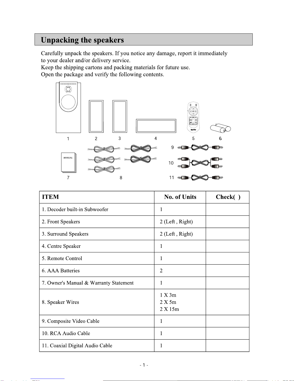
Positioning Your Speakers
Where you locate the speakers in the room plays vital role in the sound quality you will enjoy.
With each room varying in size, dimension and layout, it will be necessary to experiment
with the placement of your speakers in order to gain optimum performance. Here are some
recommendations.
. Centre Channel :
Position your Centre Speaker directly above of below your screen,facing the listening position.
. Front Channels :
Your Front Left and Right Speakers should be placed at listening height, equidistant to the left
and to the right of your screen far enough apart to ensure good stereo imaging. If they are too
far apart or too close to the corners of the room they will sound distracting and distant.
. Surround Channels :
For your Rear Left and Right Speakers, place one speaker on the left and another on the right,
to the side of, or behind the listening area.
It is suggested that they are wall mounted or alternatively placed on suitable speaker stand at
roughly 20" above the listening position.
. Subwoofer :
We recommend placing the subwoofer on a hard surface, not too close from the screen or a
computer's disc-drive system to prevent smearing the colors of the TV picture or erasing the
magnetic drive.
Here are several additional facts on installation that may be useful.
It is generally believed that low frequencies (blow 125Hz) are nondirectional and, therefore,
placement of a subwoofer within any listening room is not critical. While in theory it is true that
the larger wavelengths of extremely low frequencies are basically nondirectional, the fact is that
when installing a subwoofer within the limited confines of a room, reflections, standing waves
and absorptions generated within the room will strongly influence the performance of the
subwoofer system.
As a result, specific location of the subwoofer becomes important, and we strongly
recommend that you experiment with placement before choosing a final location.

Wiring the speakers
POWER
ON OFF
COAXIAL
VCR
Manufactured by Spirte Electronics Corp.
MADE IN KOREA
FL
RR
RL
CEN
OUT
IN 1
IN 2
AUX1
AUX2
A
N
A
L
O
G
I
N
P
U
T
OPTICAL
FR
D
I
G
I
T
A
L
I
N
P
U
T
TO REDUCE THE RISK OF ELECTRIC SHOCK,
DO NOT REMOVE COVER (OR BACK), NO USER
-SERVICEABLE PARTS INSIDE, REFER SERVICING
TO QUALIFIED SERVICE PERSONNEL.
- 3 -
Sprite Electronics Inc.
#16-1 Dangjung-Dong, Gunpo-City,
Kyunggi-Do, 435-735, KOREA
MODEL NO : SAM-8300D
OUTPUT POWER (RMS) 50 WATTS
FREQUENCY RESPONSE 35Hz - 20KHz
IMPEDANCE 4 ohms
POWER AC 120V 60Hz
5.1CH HOME THEATER SPEAKER SYSTEM
This device complies with Part
15 of the FCC Rules. Operation
is subject to the following two
conditions: (1) this device may
not cause harmful interference,
and (2) this device must accept
any interference received, including
interference that may cause
undesired operations.
Subwoofer's Rear Panel
Front / Left Speaker Front / Right Speaker
Rear / Left Speaker Rear / Right Speaker
Centre Speaker
System Subwoofer's Rear Panel
AC 120 VOLT ONLY
Audio/Video Product
E239477
3YW1 AC120V 60Hz, 67W
SPEAKER OUTPUT
RL
-
+
V
I
O
E
D
FL
RR
RL
CEN
SPEAKER OUTPUT
FR
+
_
- 4 -
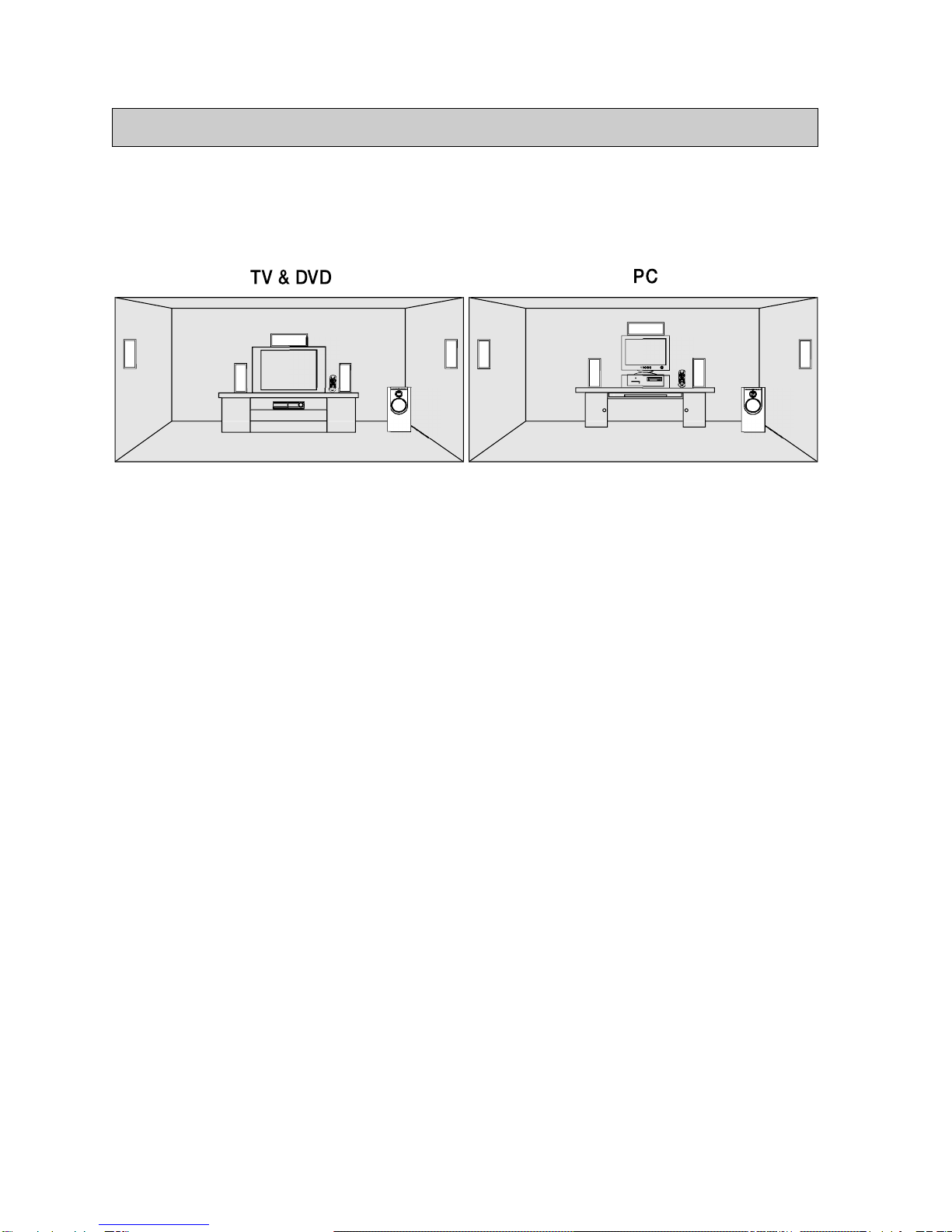
Ensure the correct polarity (+) and (-) of all speaker leads. Check to make sure there
are no wires touching on the speaker terminals, and that all wires are firmly clamped
into the terminals.
1. Press the spring loaded terminals to expose holes in the post.
2. Fully insert the stripped portion of the wire into the exposed holes.
3. Release the terminals to clamp the wire into place.
Please note :
When inserting speaker cables into any of the terminals, the black wire goes to
the - (negative)terminal, the black wire white strip goes to the + (positive)terminal.
Front/Rear/Centre(Rear panel of the speakers)
Black wire with white
Black wire
Black terminal Red terminal
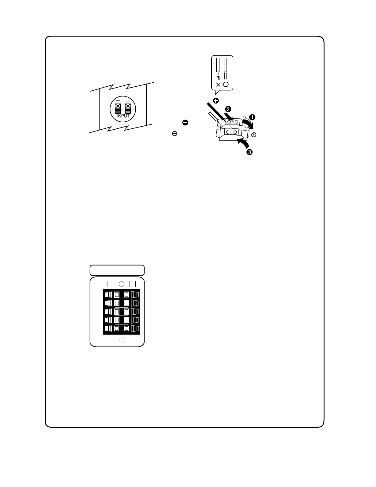
Rear panel of the system subwoofer
- 5 -
OUT
IN 1
IN 2
V
I
D
E
O
COAXIAL
OPTICAL
D
I
G
I
T
A
L
I
N
P
U
T
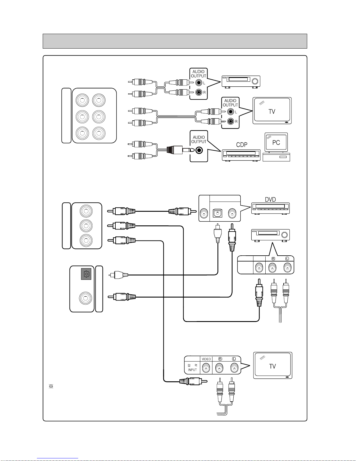
VIDEO OPTICAL COAXIAL
DIGITAL OUT
VIDEO AUDIO
출 력
OUTPUT
AUDIO
VCR/VTR
Subwoofer's Rear Panel
RL
VCR
AUX 1
AUX 2
A
N
A
L
O
G
I
N
P
U
T
VTR/VCR
1. VCR : Audio input signals from VCR/VTR.
2. AUX1 : Audio input signals from T.V.
3. AUX2 : Audio input signals from CD player, PC, etc.
Connecting your systems
Optical : Optical input terminal
from a digital source
Coaxial : Coaxial input terminal
from a digital source
Connect to VCR terminal on
the Rear Panel of the Subwoofer
Connect to AUX1 terminal on
the Rear Panel of the Subwoofer
No additional accessories or system parts are
supplied except the ones specified in this manual
- 6 -
Important : It is recommended that the main power is OFF until all connections
have been made and checked.
When connecting to video input terminals, make sure the digital input sources go to
VIDEO IN 1 terminal and analog input sources to VIDEO IN 2 terminal.
. VIDEO IN 1 : Video signals from digital input sources (Optical, Coaxial)
---> D.V.D player, Game stations.
. VIDEO IN 2 : Video signals from analog input sources (VCR,AUX1,AUX2)
---> T.V, VCR
. VIDEO OUT : Video signal output to the Screen/Monitor from the selected
video input signals (VIDEO IN 1, VIDEO IN 2)
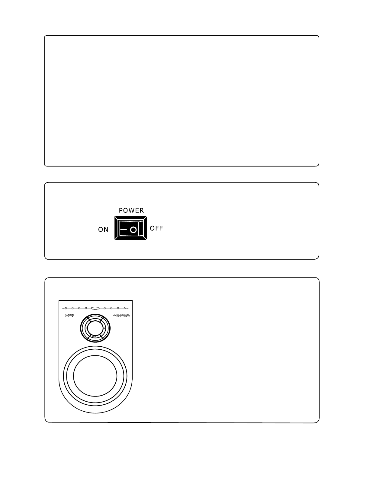
Power ON/OFF Switch
. Turns the system ON and OFF
W
O
R
E
P
STAND BY
ON/OFF
AUX 1
AUX 2 VCROPTICAL
COAXIAL
Subwoofer's Front Panel
. POWER
Once the switch in turned ON from the rear panel, press
the "POWER" Button on the front panel or on the remote
control to set the system on stand-by mode. The LED
stand-by indicator lights up.
. INPUT
Selects the audio input source. The selected source LED
lights up.
. VOLUME
Use "<" , ">"keys to adjust the master volume level of
the system.

- 7 -
Remote Control
The remote control functions are displayable on the screen only when the video
input signal from subwoofer of this system is selected.
PWR :
Turns power on and off
MUTE :
Use this to turn off the audio output temporarily.
(LED blinks)
Press again to cancel Muting mode
SETUP :
Sets the following menus/options(see below pg.8) :
-. PRO LOGIC ON/OFF
-. DRC ON/OFF
-. REAR DELAY
-. CHANNEL LEVEL
Use cursors : , , , , ENTER
Press again to return.
SURROUND MODE :
Switches the surrounding mode in the following order each time
this button is pressed :
STEREO(2.1CH) - > PHANTOM(4.1CH) - > SURROUND(5.1CH)
INPUT :
Selects different audio input sources in the following order each
time the INPUT button is pressed :
OPTICAL - > COAXIAL - > VCR - > AUX1 - > AUX2
SOURCE DISPLAY :
Displays the surround sound mode at which the audio is being played.
One of following appears on the top-left corner of the screen :
Dolby Digital
Dolby Prologic
DTS
TEST TONE :
Tests output tones of each speaker with 2 seconds interval, in the
order of :
FL - > CEN - > FR - > RR - > RL
(Press again to cancel test)
DOWN :
Volume level down
UP :
Volume level up

- 8 -
Setup Menu
PRO LOGIC ON/OFF Press SETUP -> Use or to set it ON or OFF.
Press SETUP again to return.
DRC ON/OFF Press SETUP -> press once -> Use or to set it ON or OFF.
Press SETUP again to return.
REAR DELAY Press SETUP -> press twice - > Use or to set 0 ~ 15mS.
Press SETUP again to return.
CHANNEL LEVEL Press SETUP -> press three times - > Press ENTER - > Use or to
set -10dB ~ +10dB. Press SETUP again to return
Dolby Pro Logic ON/OFF :
Dolby Pro Logic is a matrix decoder that decodes the four channels of surround sound that have
been encoded onto the stereo soundtracks of Dolby Surround program material such as VHS movies
and TV shows. Dolby Surround is a matrix encoding process that in essence "folds" Left, Center,
Right, and Surround channels onto stereo soundtracks.
A Pro Logic decoder "unfolds" the four channels on playback (without a Pro Logic decoder,
the encoded program plays in regular stereo).
DRC (Dynamic Range Compression) ON/OFF :
Allows you to enjoy a powerful sound even at a low volume level.
This provides a reduction in the dynamic range of the reproduced audio for listening conditions such
as ambient noise problems, late night listening, etc, by cutting the level of audio range that falls
above the dialog area (louder sounds) and by boosting the level of audio range that falls below the
dialog are (quieter sounds).
However, some program materials with an already restricted dynamic range, whether inherent or
because of prior processing, lies primarily within the null band and hence is not subjected to further
compression.
Rear Delay :
Allows you to adjust the rear delay setting from 0msec to 15msec in 5msec interval.
The delay time setting is essential for an optimal surround sound, regardless of the surround sound
format (Dolby Surround, Dolby Digital or DTS).
A proper delay time compensates the fact that one speaker is closer to the listener than another.
The use of the proper delay time results in sounds panning from front to back in a smooth and
natural way and avoids distracting sounds from the rear to keep your attention out from the action
of the movie.
Channel Level :
The loudness level can be adjusted between -10dB to +10dB in -1dB increments for each channel.
A setting of 0 dB is recommended for optimum performance; however, if the low frequency range is
too strong, for example, lower the subwoofer level as necessary.

- 9 -
Troubleshooting
Problem What To Do
NO SOUND -. Increase volume.
-. Check if MUTE mode is ON (Selected input LED blinks)
-. Check speaker connections.
-. Check if external devices are operating correctly.
-. Check the connections for any external components. Make sure to select
the correct source for the desired input.
NO POWER -. Check if power cord is fully plugged into the operating AC wall outlet.
-. Check if the switch on the subwoofer rear panel is turned ON.
SOUND DISTORTION -. Check that the volume level is not set too high.
-. Check that the speakers are connected correctly.
-. Check input devices settings.
-. Replace the cables.
NO REMOTE OPERATION -. Point the remote control at the sensor of the unit.
-. Reduce the distance to the player.
-. Replace the batteries with new ones.
-. Check the batteries are loaded correctly.
NO SURROUND SOUND EFFECT -. Check if SURROUND MODE is selected.
-. Check if Pro Logic in set to ON.
-. Make sure that the sound source is surround-encoded.
(Dolby Surround, Dolby Digital)
SAM - 8300D
Speaker Systems
Subwoofer : 6 1/2"
Centre : 2 X 3" + 1" Dome
Front / Rear : 3" + 1" Dome
Output Power (RMS)
Subwoofer : 25W
Centre : 10W
Front / Rear : 4 X 6W
Frequency Response
Subwoofer : 80Hz ~ 300Hz ± 3dB
Centre : 40Hz ~ 20KHz ± 3dB
Front / Rear : 80Hz ~ 20KHz ± 3dB
-Dimensions
Subwoofer : 150X300X380mm
Centre : 280X95X90mm
Front / Rear : 90X205X95mm
Input Sensitivity : 200 ~ 350mV
SAM-8800D
Speaker Systems
Subwoofer : 8"
Centre : 2 X 3"
Front / Rear : 3" + 1" Dome
Output Power (RMS)
Subwoofer : 30W
Centre : 13W
Front / Rear : 4 X 6W
Frequency Response
Subwoofer : 80Hz ~ 300Hz ± 3dB
Centre : 40Hz ~ 20KHz ± 3dB
Front / Rear : 80Hz ~ 20KHz ± 3dB
-Dimensions
Subwoofer : 210X410X412mm
Centre : 332X126X143mm
Front / Rear : 126X228X143mm
Input Sensitivity : 200 ~ 350mV
SAM-6500D
Speaker Systems
Subwoofer : 6 1/2"
Centre : 2 X 3"
Front/Rear : 3" + 1" Dome
Output Power (RMS)
Subwoofer : 25W
Centre : 10W
Front/Rear : 4 X 6W
Frequency Response
Subwoofer : 80Hz ~ 300Hz ± 3dB
Centre : 40Hz ~ 20KHz ± 3dB
Front/Rear : 80Hz ~ 20KHz ± 3dB
-Dimensions
Subwoofer : 230X510X250mm
Centre : 280X90X90mm
Front / Rear : 90X990X90mm
Input Sensitivity : 200 ~ 350mV
Specifications
Space-Saving Slim Design
-. Please use only the supplied remote control for this system.
This manual suits for next models
2
Table of contents


