SPX Hankinson HHE Series User manual

HHE, HHL, HHS SERIES
Pressure-Swing Desiccant Type Compressed Air Dryers with AccuShift™ Switching Valves
FORM NO.: 3162258 REVISION: 03/2014 READ AND UNDERSTAND THIS MANUAL PRIOR TO OPERATING OR SERVICING THIS PRODUCT.
INSTRUCTION MANUAL
MODELS
RATED
FLOW
REFER
AS
MODELS
HHE
SERIES
w/ Timer
Controller
HHL
SERIES
w/ Level 1
Controller
HHS
SERIES
w/ Level 2
Controller
HHE-40
HHE-60
HHE-90
HHL-40
HHL-60
HHL-90
HHS-40
HHS-60
HHS-90
40 SCFM
60 SCFM
90 SCFM
40
60
90
HHE-115
HHE-165
HHE-260
HHL-115
HHL-165
HHL-260
HHS-115
HHS-165
HHS-260
115 SCFM
165 SCFM
260 SCFM
115
165
260
HHE-370
HHE-450
HHE-590
HHL-370
HHL-450
HHL-590
HHS-370
HHS-450
HHS-590
370 SCFM
450 SCFM
590 SCFM
370
450
590
HHE-750
HHE-930
HHE-1130
HHL-750
HHL-930
HHL-1130
HHS-750
HHS-930
HHS-1130
750 SCFM
930 SCFM
1130 SCFM
750
930
1130
HHE-1350
HHE-1550
HHE-2100
HHL-1350
HHL-1550
HHL-2100
HHS-1350
HHS-1550
HHS-2100
1350 SCFM
1550 SCFM
2100 SCFM
1350
1550
2100
HHE-3000
HHE-4100
HHE-5400
HHL-3000
HHL-4100
HHL-5400
HHS-3000
HHS-4100
HHS-5400
3000 SCFM
4100 SCFM
5400 SCFM
3000
4100
5400

Contents
1. GENERAL SAFETY INFORMATION................................ 1
2. RECEIVING, MOVING, UNPACKING .............................. 1
3. DESCRIPTION ................................................................. 2
4. INSTALLATION................................................................. 7
5. CONTROLLERS – GENERAL.......................................... 15
6. CONTROLLER – TIMER BASED..................................... 17
7. CONTROLLER – LEVEL 1............................................... 20
8. CONTROLLER – LEVEL 2............................................... 31
9. OPERATION..................................................................... 48
10. MAINTENANCE ............................................................... 54
11. TROUBLESHOOTING ..................................................... 55
12. REPLACEMENT PARTS .................................................. 56
13. NOTES ............................................................................. 64
WARRANTY ............................................................................. 65

— 1 —
2. RECEIVING, MOVING, UNPACKING
2.1 Receiving:
•This shipment has been thoroughly checked, packed and
inspected before leaving our plant.
•It was received in good condition by the carrier and was so
acknowledged.
•Check for visible loss or damage. If this shipment shows evidence
of loss or damage at time of delivery to you, insist that the carrier’s
agent make a notation of this loss or damage on the delivery
receipt.
2.2 Moving:
CAUTION: Use lifting lugs or forklift. Do not lift equipment
by piping.
2.3 Unpacking:
•Check for concealed loss or damage. When a shipment has been
delivered to you in apparent good order, but concealed damage
is found upon unpacking, notify the carrier immediately and insist
that his agent inspects the shipment.
•Fifteen days from receipt of shipment is the maximum time limit
for requesting such inspection.
•Concealed damage claims are not our responsibility as our terms
are F.O.B. point of shipment.
1. GENERAL SAFETY INFORMATION
1.1 Pressurized Devices
•This equipment is a pressure-containing device.
•Do not exceed maximum operating pressure as shown on the
equipment serial number tag.
•Verify that equipment is fully de-pressurized before performing
service or maintenance functions.
1.2 Electrical:
•This equipment requires electricity to operate.
•Install equipment in compliance with national and local electrical
codes.
•Standard equipment is supplied with NEMA 4,4X electrical
enclosures and is not intended for installation in hazardous
environments.
•Disconnect power supply to equipment when performing any
electrical service work.
1.3 Breathing Air:
•Air treated by this equipment may not be suitable for breathing
without further purication.
•Refer to OSHA standard 1910.134 for the requirements for
breathing quality air.
1.4 Noise:
CAUTION: Do not operate dryer without mufflers
installed.
1.5 High Velocity Air:
CAUTION: Do not stand near mufflers during tower
depressurization.

— 2 —
3. DESCRIPTION
3.1 Dryer Function
• Dual tower regenerative desiccant dryers are an economical
and reliable way to dry compressed air to dew points below the
freezing point of water (dew points as low as -100°F (-73.3°C)
[0.2 ppmV @ 100 psig, 6.9 barg] are possible) or reduce the
moisture content of compressed air when used in critical process
applications.
• These dryers continuously dry compressed air by using two
identical towers, each containing a desiccant bed. While one
tower is on-stream drying, the other tower is off-stream being
regenerated (reactivated, i.e., dried out). The towers are
alternated on- and off-stream so that dry desiccant is always in
contact with the wet compressed air. In this way a continuous
supply of dry air downstream of the dryer is possible.
• Desiccant dryers lower the dew point of compressed air by
adsorbing the water vapor present in the compressed air onto
the surface of the desiccant. Desiccant is a highly porous solid
containing extensive surface area.
• Adsorption occurs until the partial pressure of the water vapor
in the air and that on the surface of the desiccant come into
equilibrium. As adsorption occurs, heat is released (referred to
as the heat of adsorption) and is stored in the bed for use during
regeneration.
• Desiccant is regenerated by driving off (desorbing) the water
collected on its surface. Pressure-swing (also called heatless or
heater-less because no outside heat is added) dryers regenerate
by expanding a portion (approximately 14 -15% at 100 psig,
6.9 barg) of the dried air to atmospheric pressure. This “swing in
pressure” causes the expanded air to become very dry (have a
very low vapor pressure). This very dry air (called purge air) plus
the stored heat of adsorption allows the moisture to desorb from
the desiccant. The purge air then carries the desorbed water out
of the dryer.
3.2 Automatic Purge Saving System
Featured with the Level 2 Controller, the Automatic Purge Saving
System is designed to save energy (purge air) when pressure-swing
dryers are operated at reduced loads.
The Purge Saving System operates by monitoring the changes
in temperature within the desiccant beds. These changes in
temperature are the result of heat (thermal energy) that is released
when a bed is on-line drying (heat of adsorption), and the heat
that is used when a bed is off-line being regenerated (heat of
desorption). The magnitude of these changes in temperature is an
indirect measure of the water vapor content in the air being dried.
This information is used to determine the time a tower stays on line
during the drying cycle.

— 3 —
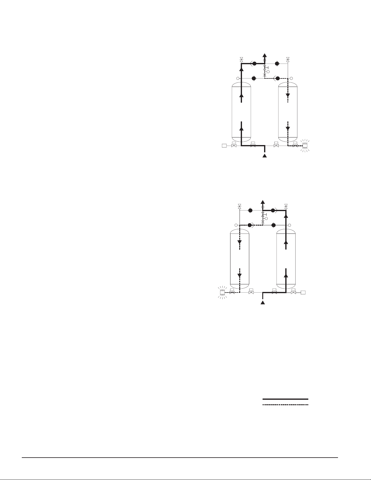
3.3 Description of Operation – Dryer
3.3.1 Models 40 to 3000 w/ Shuttle Valve
(Refer to Fig. 3-1a.) Compressed air ows through inlet shuttle valve (3)
to tower (4A) where the air is dried. After the air is dried it ows through
outlet shuttle valve (5) and then to the dryer outlet. A portion of the dry
air, the purge stream, branches off from the main air stream prior to
the outlet. The purge stream ow rate is controlled by the adjustable
purge rate valve (6) and the two purge orices (7).
The purge ow, which has been throttled to near atmospheric pressure,
is directed to tower (4B). As the purge ow passes over the desiccant
in tower (4B), it removes the water vapor, which was deposited there
while the tower was on-line drying. The purge air then passes through
purge and repressurization valve (9B) (normally closed) and purge
mufer (10B) to the atmosphere.
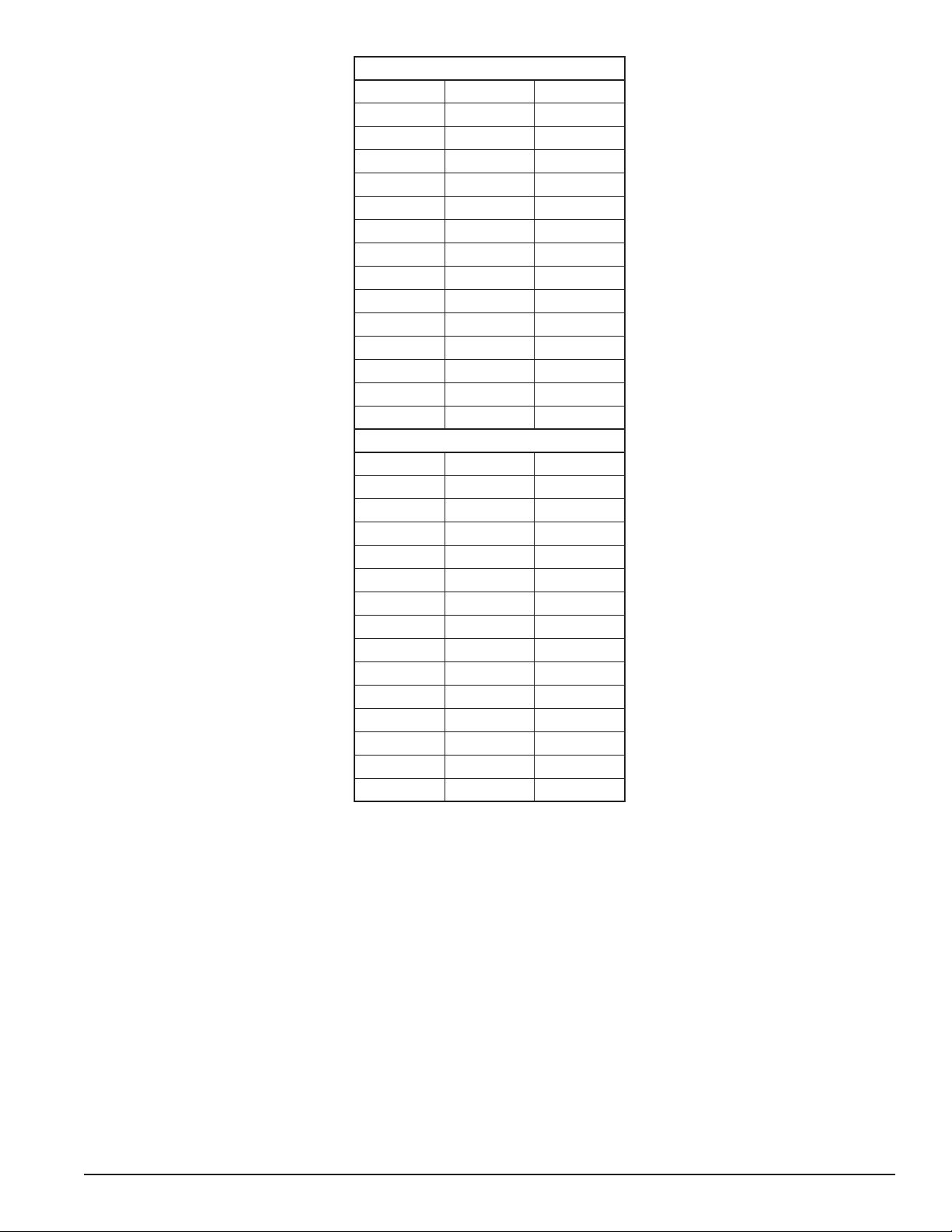
After regeneration, purge and repressurization valve (9B) (normally
closed) closes allowing tower (4B) to repressurize slowly. Adequate
repressurization time is allowed so that tower (4B) is fully repressurized
before tower switchover. After a controlled time period, purge and
repressurization valve (9A) (normally closed) then opens. This causes
the inlet and outlet shuttle valves to shift, directing the air ow through
tower (4B).
(Refer to Fig. 3-1b.) Tower (4B) is now drying the main air stream
while tower (4A) is being regenerated by the purge air stream. The
operation of the purge and repressurization (normally closed) valves is
sequenced by the control system located in the electrical enclosure.
8. Safety Valve
9. Purge and Repres-
surization Valves
10. Purge Mufflers
11. Moisture Indicator
A Left Tower Suffix
B Right Tower Suffix
TOWER 4B REGENERATING
4B
TOWER
Purge Stream
Process Stream
1. Tower Pressure Gauges
2. Purge Pressure Gauge
3. Inlet Shuttle Valve
4. Desiccant Drying Towers
5. Outlet Shuttle Valve
6. Adjustable Purge Rate Valve
7. Purge Orifices
9A
FIGURE 3-1a
TOWER 4A DRYING
INLET
TOWER
4A
1
762
OUTLET
5
8
9B
10B
1
7
9A
TOWER 4B DRYING
TOWER
4A
INLET
FIGURE 3-1b
TOWER 4A REGENERATING
1
76
1
8
27
9B
4B
TOWER
10A
10B10A
11
5
11
OUTLET
3
3
— 4 —
3.3.2 Models 4100 to 5400 w/ Check Valves
(Refer to Fig. 3-2a.) Compressed air ows through inlet switching
valve (3A) (normally open) to tower (4A) where the air is dried. After
the air is dried it ows through outlet check valve (5A) and then to
the dryer outlet. A portion of the dry air, the purge stream, branches
off from the main air stream prior to the outlet. The purge stream ow
rate is controlled by the adjustable purge rate valve (6) and the single
purge orice (7).
The purge ow, which has been throttled to near atmospheric pressure,
is directed through purge check valve (5D) to tower (4B). As the purge
ow passes over the desiccant in tower (4B), it removes the water
vapor which was deposited while the tower was on-line drying. The
purge air then passes through purge and repressurization valve (9B)
(normally closed) and purge mufer (10B) to the atmosphere.
After regeneration, purge and repressurization valve (9B) (normally
closed) closes allowing tower (4B) to re-pressurize slowly. Adequate
repressurization time is allowed so that tower (4B) is fully re-
pressurized before switchover. After a controlled time period, air
inlet switching valve (3B) (normally open) opens and inlet-switching
valve (3A) (normally open) closes, purge and repressurization
valve (9A) (normally closed) then opens.
(Refer to Fig. 3-2b.) Tower (4B) is now drying the main air stream while
tower (4A) is being regenerated by the purge air stream. The operation
of the inlet switching (normally open) and purge and repressurization
(normally closed) valves is sequenced by the control system located
in the electrical enclosure.
7
INLET
OUTLET
TOWER
4A
3A9A
5C
1
8
7
62
3B 9B
TOWER
4B
5A 5B
5D
8
1
1. Tower Pressure Gauges
2. Purge Pressure Gauge
3. Inlet Switching Valves
4. Desiccant Drying Towers
5. Check Valves
6. Adjustable Purge Rate Valve
7. Purge Orifice
8. Safety Valves
9. Purge and Repres-
surization Valves
10. Purge Mufflers
11. Moisture Indicator
A & C Left Tower Suffixes
B & D Right Tower Suffixes
Process Stream
Purge Stream
INLET
OUTLET
4A
10A
9A 3A
TOWER
8
1
6
4B
3B 9B
TOWER
2
8
1
5C 5D
FIGURE 3-2a
TOWER 4A DRYING
TOWER 4B REGENERATING
FIGURE 3-2b
TOWER 4B DRYING
TOWER 4A REGENERATING
11
5A 11 5B
10B
10
A1
0B

— 5 —
3.3.3 Models 40 to 450 (High Pressure Option)
(Refer to Fig. 3-3a.) Compressed air ows through inlet switching
valve (3A) (normally open) to tower (4A) where the air is dried. After
the air is dried it ows through shuttle valve (5) and then to the dryer
outlet. A portion of the dry air, the purge stream, branches off from
the main air stream prior to the outlet. The purge stream ow rate is
controlled by the adjustable purge rate valve (6) and the two purge
orices (7).
The purge ow, which has been throttled to near atmospheric pressure,
is directed to tower (4B). As the purge ow passes over the desiccant
in tower (4B), it removes the water vapor which was deposited while
the tower was on-line drying. The purge air then passes through
purge and repressurization valve (9B) (normally closed) and purge
mufer (10B) to the atmosphere.
After regeneration, purge and repressurization valve (9B) (normally
closed) closes allowing tower (4B) to re-pressurize slowly. Adequate
repressurization time is allowed so that tower (4B) is fully re-
pressurized before switchover. After a controlled time period, air
inlet switching valve (3B) (normally open) opens and inlet-switching
valve (3A) (normally open) closes, purge and repressurization
valve (9A) (normally closed) then opens.
(Refer to Fig. 3-3b.) Tower (4B) is now drying the main air stream while
tower (4A) is being regenerated by the purge air stream. The operation
of the inlet switching (normally open) and purge and repressurization
(normally closed) valves is sequenced by the control system located
in the electrical enclosure.
8. Safety Valve
9. Purge and Repres-
surization Valves
10. Purge Mufflers
11. Moisture Indicator
A Left Tower Suffix
B Right Tower Suffix
4B
TOWER
Purge Stream
Process Stream
1. Tower Pressure Gauges
2. Purge Pressure Gauge
3. Inlet Switching Valves
4. Desiccant Drying Towers
5. Shuttle Valve
6. Adjustable Purge Rate Valve
7. Purge Orifices
9A
3A
INLET
TOWER
4A
1
762
8
9B
3B
10B
1
7
9A
TOWER
4A
INLET
FIGURE 3-3b
TOWER 4A REGENERATING
TOWER 4B DRYING
3A 3B
1
76
1
8
27
9B
4B
TOWER
10A
10B10A
5
11
OUTLET
OUTLET
11 5
FIGURE 3-3a
TOWER 4A DRYING
TOWER 4B REGENERATING

— 6 —
3.4 Automatic Purge Saving System
(Refer to Figure 3-4a for Models 40 through 3000 and Figure 3-4b for
Models 4100 through 5400.)
Assume tower A is on-line drying while tower B has just gone off-line
to be regenerated. At the beginning of tower B’s regeneration cycle a
thermistor temperature measurement is made at position B1. After the
tower has been regenerated, another measurement is made at B1. The
drop in temperature sensed during regeneration is an indirect measure
of the water vapor content of the inlet air. The Automatic Purge Saving
System’s microprocessor then uses this information to calculate an
allowable temperature rise in the bed during the drying cycle.
When tower B goes back on-line, a temperature probe at position B2
measures the initial bed temperature at this point and then monitors
the bed until the calculated temperature rise occurs. The temperature
rise occurs as heat of adsorption is released during the drying process.
The time for the temperature rise to occur depends on ow rate. At
100% ow the temperature rise takes 5 minutes, at 50% ow it takes
10 minutes.
NOTE: If after 30 minutes, the bed temperature has not risen to the
calculated value, the dryer will automatically switch towers.
When the calculated temperature rise is reached, the towers switch
with tower A now drying and tower B being regenerated. Tower B
regenerates for 3.9 minutes, re-pressurizes, and remains idle until it
is called upon for the next drying cycle.
1. Tower Pressure Gauges
2. Purge Pressure Gauge
3. Inlet Shuttle or Switching
Valves
4. Desiccant Drying Towers
5. Shuttle or Check Valve(s)
6. Adjustable Purge Rate Valve
7. Purge Orifice(s)
Purge Stream
Process Stream
8. Safety Valve(s)
9. Purge and Repres-
surization Valves
10. Purge Mufflers
11. Moisture Indicator
A & C Left Tower Suffix(es)
B & D Right Tower Suffix(es)
11
OUTLET
INLET
4A
10A
9A 3A
TOWER
8
1
5A
5C
6
7
4B
3B 9B
10B
TOWER
5B
25D
8
1
FIGURE 3-4b
Models 4100 through 5400
TOWER 4A DRYING
TOWER 4B REGENERATING
A2
A1 B1
B2
4A 4B
TOWER 4A DRYING
TOWER 4B REGENERATING
10A
9A
FIGURE 3-4a 10B
INLET
9B
7
1
TOWER
1
26
8
7
TOWER
Models 40 through 3000
A1
A2
B1
B2
OUTLET
11 5
3

— 7 —
4. INSTALLATION
4.1 Location in the compressed air system
NOTE: The air compressor should be adequately sized to handle
air system demands as well as purge loss. Failure to take this into
account could result in overloading air compressors and/or insufcient
air supply downstream. It is desirable to install the dryer where the
compressed air is at the lowest possible temperature (downstream of
aftercoolers) and the highest possible pressure (upstream of pressure
reducing valves) without exceeding the maximum operating pressure
of the equipment. (Refer to Figure 4-1)
4.1.4 Heatless Pressure-Swing Desiccant Air Dryer
4.1.5 Afterlter(s) –
To ensure downstream air purity (prevent desiccant dust from
traveling downstream) adequate ltration downstream of the dryer
is required.
• First Afterlter - Particulate Removal -Typically 1-micron ltration
is specied although ner ltration is available.
• Second Afterlter - Oil Vapor Adsorption -This lter is used to
remove oil vapor and its subsequent taste and odor and to protect
down-stream components from solid particles 0.01 micron and
larger.
NOTE: By-pass lines and isolation valves are recommended so
that maintenance work can be performed without shutting off the air
supply.
4.1.1 Aftercooler/Separator –
Compressed air entering dryer must be cooled to a temperature of
140°F (60°C) or lower. Use of an aftercooler and condensate separator
may be necessary to reduce inlet air temperature to an acceptable
level.
NOTE: Installation of a refrigerated dryer ahead of a pressure-swing
desiccant dryer does not increase desiccant dryer capacity or reduce
purge ow requirements.
4.1.2 Receiver(s) –
Air receivers dampen pulsations from the compressor discharge line
and can eliminate some of the condensed moisture that is carried over
from the aftercooler and separator. They also provide a reservoir of
stored air for response to system demands in excess of compressor
capacity. Size and location of receivers in the compressed air system
need to be considered carefully. Flows must not exceed the adjusted
maximum inlet capacity of the desiccant air dryer.
4.1.3 Prelter(s) –
Adequate ltration is required upstream of the dryer in order to
protect the desiccant bed from contamination. The following ltration,
equipped with automatic condensate drains, is recommended:
• First Prelter - Particulate/Gross Liquid Removal - On heavily
contaminated systems, a gross contaminant lter to remove solids
and high inlet liquid concentrations should be used.
•Second Prefilter - Oil Aerosol Removal - On systems with
lubricated compressors, an oil removal filter to remove oil
aerosols and protect the desiccant beds from oil contamination
is required.
4.2 Physical Location
The dryer must be installed with suitable overhead protection
as well as clearance to change desiccant. Sufficient clearance
around the periphery of the dryer should be provided to allow
maintenance personnel access to all areas for routine inspections
and adjustments.
4.3 Minimum & Maximum Operating Conditions
The compressed air supply to the dryer inlet should be checked
periodically to ensure that dryer design specifications are not
exceeded. Normally the compressor installation includes intercoolers,
aftercoolers, separators, receivers, or similar equipment, which
adequately pretreat the compressed air supply in order to avoid
excessively high air temperatures and liquid slugging of downstream
equipment.
4.4 Maximum Operating Pressure (MOP):
•150 psig (10.3 barg) is standard.
•250 psig (17.2 barg) is optional.
Refer to Dryer Serial Number Tag.
WARNING - Do not operate the dryer at pressures above the
maximum operating pressure shown on the serial number tag.
NOTE: Consult factory for applications requiring higher maximum
operating pressures.
Compressor AftercoolerSeparator Receiver Prefilters Afterfilters ReceiverDesiccant Dryer
Figure 4-1
Figure 4-1

— 8 —
Figure 4-2
40-450 SCFM General Arrangement
(continued on next page)
WARNING:Disconnectthemain power
supplybeforeremovingthiscove r.
CENTERLINE OF CUSTOMER
INLET/OUTLET CONNECTIONS
M
(MAX)
D
E
C
B
J
LIFTING LUG
DESICCANT FILL PORT
LEFT CHAMBER
PRESSURE GAUGE
MOISTURE INDICATOR
RIGHT CHAMBER
PRESSURE GAUGE
CONTROL ENCLOSURE
DESICCANT DRAIN PORT
G
H
P
AIR OUTLET
7/8”X 1 1/4” SLOT (TYP 4 PLCS)
[22mm] [32mm]
A
L
(MAX)
F
N
(MAX)
P
AIR INLET
TOP VIEW
FRONT VIEW RIGHT SIDE VIEW
RIGHT CHAMBER REMOVED FOR CLARITY
REAR VIEW
ASME PRESSURE
RELIEF VALVE
OUTLET SHUTTLE
VALVE ASSY
PILOT AIR FILTER
PURGE PRESSURE GAUGE
& REGULATOR
PURGE ADJUSTING VALVE
ASME CODE TAG
INLET SHUTTLE
VALVE ASSY
PURGE EXHAUST
VALVE
PURGE EXHAUST
MUFFLER

— 9 —
Figure 4-2
40-450 SCFM General Arrangement
(continued from previous page)
DIMENSIONS IN INCHES
MODEL 40 60 90 115 165 260 370 450
A27.5/8 27.5/8 27.5/8 38.3/8 38.3/8 41.3/8 49.3/8 49.3/8
B13.13/16 13.13/16 13.13/16 19.13/16 19.13/16 20.11/16 24.11/16 24.11/16
C1.1/4 1.1/4 1.1/4 1.1/4 1.1/4 1.1/4 1.1/4 1.1/4
D29.1/2 29.1/2 29.1/2 35.1/2 35.1/2 35.1/2 35.1/2 35.1/2
E14.3/4 14.3/4 14.3/4 17.3/4 17.3/4 17.3/4 17.3/4 17.3/4
F2.13/16 2.13/16 2.13/16 2.13/16 2.13/16 3.1/4 3.1/4 3.1/4
G14 14 14 15 15 15 16 16
H39 54 71 45 45 63 53 61
J1.3/4 1.3/4 1.3/4 1.3/4 1.3/4 2.3/4 2.3/4 2.3/4
L35 35 37 50 50 51 58 58
M35 35 35 41 41 41 42 42
N49 64 81 57 57 75 65 73
P1 NPT 1 NPT 1 NPT 1 NPT 1 NPT 2 NPT 2 NPT 2 NPT
WT/LBS 365 445 575 685 685 1010 1215 1350
DIMENSIONS IN MILLIMETERS
MODEL 40 60 90 115 165 260 370 450
A702 702 702 975 975 1051 1254 1254
B351 351 351 487 487 525 627 627
C32 32 32 32 32 32 32 32
D749 749 749 902 902 902 902 902
E375 375 375 451 451 451 451 451
F71 71 71 71 71 83 83 83
G356 356 356 381 381 381 406 406
H991 1372 1803 1143 1143 1600 1346 1549
J44 44 44 44 44 70 70 70
L889 889 948 1264 1264 1305 1470 1470
M889 889 889 1041 1041 1041 1062 1062
N1235 1616 2047 1437 1437 1894 1658 1861
P1 NPT 1 NPT 1 NPT 1 NPT 1 NPT 2 NPT 2 NPT 2 NPT
WT/KGS 166 202 261 311 311 458 551 612
NOTE: Dimensions and weights are for reference only. Request certied drawings for construction purposes.

— 10 —
Figure 4-3
590-3000 SCFM General Arrangement
(continued on next page)
WARNING:Disconnectthemainpower
supplybeforeremovingthiscover.
P
AIR OUTLET
F
H
PURGE
EXHAUST
MUFFLER
ASME CODE TAG
PILOT AIR
FILTER
P
AIR INLET
ASME PRESSURE
RELIEF VALVE
DESICCANT DRAIN PORT
L
(MAX)
N
(MAX)
CONTROL
ENCLOSURE
RIGHT CHAMBER
PRESSURE GAUGE
PURGE PRESSURE GAUGE
MOISTURE INDICATOR
DESICCANT FILL PORT
7/8”X 1-1/4” SLOT (TYP 4 PLACES)
[22mm] [32mm]
A
B
LEFT CHAMBER
PRESSURE GAUGE
LIFTING LUG
PURGE PRESSURE
ADJUSTMENT VALVE
CENTERLINE OF CUSTOMER
INLET/OUTLET CONNECTIONS
M
(MAX)
D
E
C
G
TOP VIEW
FRONT VIEW RIGHT SIDE VIEW
(Models 590 through 1350)
RIGHT CHAMBER REMOVED FOR CLARITY
REAR VIEW
F
H
P
AIR INLET
G
BOTTOM RIGHT SIDE VIEW
(Models 1550, 2100 and 3000)
RIGHT CHAMBER REMOVED FOR CLARITY

— 11 —
Figure 4-3
590-3000 SCFM General Arrangement
(continued from previous page)
DIMENSIONS IN INCHES
MODEL 590 750 930 1130 1350 1550 2100 3000
A46.3/4 47.9/16 52.11/16 56.7/16 57.5/16 63.1/8 69.13/16 73.3/8
B23.3/8 23.13/16 26.5/16 28.1/4 28.11/16 31.9/16 34.7/8 36.11/16
C1.1/4 1.1/4 1.1/4 1.1/4 1.1/4 1.1/4 1.1/4 1.1/4
D45.1/2 45.1/2 53.1/2 53.1/2 53.1/2 53.1/2 53.1/2 59.1/2
E22.3/4 22.3/4 26.3/4 26.3/4 26.3/4 26.3/4 26.3/4 29.3/4
F3.1/4 3.1/4 3.1/4 5.1/8 5.1/8 5.9/16 5.9/16 5.9/16
G9.3/16 9.11/16 11.7/16 11 11 5.1/4 6.3/16 8.1/2
H97.5/16 100.13/16 105.9/16 107.1/8 112.1/8 109.1/2 111.5/16 117.3/8
L55 57 63 66 68 74 82 86
M51 51 59 59 59 59 59 67
N104 107 112 115 120 117 119 125
P2 NPT 2 NPT 2 NPT 3 FLANGE 3 FLANGE 4 FLANGE 4 FLANGE 4 FLANGE
WT/LBS 1473 2134 2414 2875 3722 4167 4417 9010
DIMENSIONS IN MILLIMETERS
MODEL 590 750 930 1130 1350 1550 2100 3000
A1187 1208 1338 1434 1456 1604 1773 1864
B594 604 669 717 728 802 886 932
C32 32 32 32 32 32 32 32
D1156 1156 1359 1359 1359 1359 1359 1511
E578 578 679 679 679 679 679 756
F83 83 83 130 130 141 141 141
G234 247 291 279 279 133 157 216
H2472 2561 2681 2721 2848 2781 2827 2981
L1387 1438 1603 1673 1724 1876 2080 2172
M1295 1295 1499 1499 1499 1499 1499 1693
N2631 2720 2841 2924 3051 2980 3026 3180
P2 NPT 2 NPT 2 NPT 3 FLANGE 3 FLANGE 4 FLANGE 4 FLANGE 4 FLANGE
WT/KGS 668 968 1095 1304 1688 1890 2004 4087
NOTE: Dimensions and weights are for reference only. Request certied drawings for construction purposes.

— 12 —
Figure 4-4
4100-5400 SCFM General Arrangement
(continued on next page)
FLOW FLOW
FLOW FLOW
FLOW FLOW
FLOW FLOW
M
(MAX)
D
E
CB
A
L
(MAX)
7/8”X 1-1/4” SLOT (TYP 4 PLACES)
[22mm] [32mm]
ASME PRESSURE
RELIEF VALVE
CENTERLINE OF CUSTOMER
INLET/OUTLET CONNECTIONS
LIFTING LUG
PURGE PRESSURE
ADJUSTMENT VALVE
LEFT CHAMBER
PRESSURE GAUGE
DESICCANT FILL PORT
MOISTURE INDICATOR
PURGE PRESSURE GAUGE
RIGHT CHAMBER
PRESSURE GAUGE
CONTROL
ENCLOSURE
PURGE EXHAUST MUFFLER
DESICCANT DRAIN PORT
N
OVERALL
LENGTH
J
G
P
AIR INLET
H
PILOT AIR FILTER
FP
AIR OUTLET
TOP VIEW
FRONT VIEW RIGHT SIDE VIEW
RIGHT CHAMBER REMOVED FOR CLARITY
REAR VIEW
— 13 —
Figure 4-4
4100-5400 SCFM General Arrangement
(continued from previous page)
DIMENSIONS IN INCHES
MODEL 4100 5400
A82.7/8 93.3/8
B41.7/16 46.11/16
C1.1/4 1.1/4
D59.1/2 63.1/2
E29.3/4 31.3/4
F33.3/16 35.7/8
G13.13/16 19.7/16
H115.13/16 116.3/16
J36.3/16 38.7/8
L100 105
M88 89
N124 124
P6 FLANGE 6 FLANGE
WT/LBS 9900 12000
DIMENSIONS IN MILLIMETERS
MODEL 4100 5400
A2106 2372
B1053 1186
C32 32
D1511 1613
E756 806
F843 911
G351 494
H2942 2951
J919 988
L2537 2667
M2227 2253
N3158 3158
P6 FLANGE 6 FLANGE
WT/KGS 4500 5445
NOTE: Dimensions and weights are for reference only. Request certied drawings for construction purposes.

— 14 —
4.5 Minimum Operating Pressures:
4.5.1 For 150 psig (10.3 barg) MOP models -
•60 psig (4.1 barg) is the minimum operating pressure for dryers
operated on ISO classes 1, 2, 3, and 4.
4.5.2 For 250 psig (17.2 barg) MOP models -
•120 psig (8.3 barg) is the minimum operating pressure for dryers
operated on ISO classes 1, 2, 3, and 4.
Refer to Dryer Serial Number Tag.
WARNING - Do not operate the dryer at pressures below the
minimum operating pressure shown on the serial number tag.
NOTE: Consult factory for applications requiring lower minimum
operating pressures.
4.6 Maximum Compressed Air Temperature at Dryer
Inlet:
•140°F (60°C) for all models.
4.7 Ambient Temperatures:
4.7.1 Minimum Ambient Temperature
•Standard units: 35°F (2°C)
•Units with optional low ambient package: -20°F ( -29°C)
4.7.2 Maximum Ambient Temperature
•120°F (49°C)
NOTE: If dryer is installed in ambients below 35°F (2°C), low ambient
protection requiring heat tracing and insulation of the prelter bowls,
auto drains and/or sumps, and lower piping with inlet switching and
purge/repressurization valves is necessary to prevent condensate
from freezing. If installing heat tracing, observe electrical class code
requirements for type of duty specied. Purge mufers and their relief
mechanisms must be kept clear from snow and ice buildup that could
prevent proper discharge of compressed air.
4.8 Mounting
Install dryer on a level pad. Holes are provided in the dryer base
members for oor anchors.
NOTE: Floor anchors must be used if area is subject to vibration.
4.9 Piping
Inlet and Outlet connections
Observe locations of inlet and outlet connections as shown in Figures
4-2, 4-3 or 4-4 and connect inlet and outlet piping as indicated.
NOTE: All piping must be supported so as not to bear on the dryers
or lters.
4.10 Isolation Valves
If isolation or bypass valves are installed, care must be used to
ensure that equipment is pressurized slowly. This is particularly true if
isolation valves are placed before and after pre and afterlters where
rapid pressurization could cause excessive pressure drop across
lter elements.
NOTE: When quarter-turn valves (e.g. ball or buttery valves) are
used for isolation of pressure components, care should be taken to
open or close valves slowly.
4.11 Electrical Connections
Refer to the appropriate controller sections for detailed information
on connections, ratings, and operation of the Level 1 or Level 2
Controller.
NOTE: Refer to the dryer serial number tag for allowable voltages,
frequency and power rating.
4.12 Provisions for Purge Exhaust
•Purge exhaust must be routed through the factory supplied
mufers or piped to a remote location.
• Purge mufers - If shipped separately, install purge exhaust
mufers in the locations shown in Figures 4-2, 4-3 or 4-4.
• If purge exhaust is piped to a mufer located in a remote location,
choose a combination of diameters, lengths, and turns that limits
the additional pressure drop to 1 psid or less.
WARNING - Do not operate dryer without installed mufflers.
Exhausting compressed air directly to atmosphere will result in
noise levels above OSHA permissible levels and rapidly expanding
gas could potentially cause harm to persons or property.
4.13 Initial Desiccant Charge
The dryer is shipped complete with desiccant and is ready to operate
after piping and electrical connections are made and controller settings
are established.
4.14 Icon Identication
P
P
P
Left Tower
Pressure Gauge
Right Tower
Pressure Gauge
Air Outlet
Air Inlet
Purge
Pressure Gauge
Electrical
Inlet

— 15 —
5. CONTROLLERS – GENERAL
5.1 Overview
The solid-state dryer controller is located in a polycarbonate, NEMA
Class 4/4X, IP66 rated electrical enclosure mounted to a center panel
located between the two desiccant towers. Controls are available in
three functional levels. The Timer Controller offers a xed-time cycle
that provides a dew point corresponding to ISO compressed air quality
class 2. Both the Level 1 and Level 2 controls offer four xed-time
cycles that provide dew points corresponding to ISO compressed air
quality classes 1 through 4. A key difference between the Level 1 and
Level 2 controls is the way in which they address energy savings. When
inlet ow is less than the adjusted rated capacity of the dryer, average
purge air requirements are reduced. This reduction can translate to
energy savings at the air compressor.
The Level 1 Controller offers 8 selectable xed-cycle Energy (purge)
Saver modes (0% to 70% in 10 % increments) to reduce purge time
to match the load on the dryer.
Level 2 Controllers feature the Automatic Purge Saving System
(APSS) as described in Sections 3.2 and 3.4. When Level 2 Controllers
are operated in demand rather than xed cycle modes, the APSS
automatically adjusts to dryer loading and extends drying time when
possible. Average purge use is thus automatically reduced.
A feature-by-feature comparison of each controller can be found in
Table 5-1.
Table 5-1
Feature Comparison
(continued on next page)
Desiccant Dryer Controllers Timer
Controller
Level 1
Fixed Cycle Only
Level 2
Fixed Cycle
and APSS
Category Feature
General
AC Input Voltage: 100-240 VAC, 50-60 Hz (See NOTE 1) •
AC Input Voltage: 85-264 VAC, 47-63 Hz (See NOTE 1) • •
DC Input Voltage: 11.5-28 VDC (See NOTE 1) • •
Auxiliary power terminals (See NOTE 2) • •
Solenoid valve coil voltage 12 VDC 12 VDC 12 VDC
NEMA 4/4X, IP 66 electrical enclosure rating •••
Soft on/off switch with two power recovery modes (See NOTE 3) • •
Tower status LEDs (amber=drying) •
Tower status LEDs (green=drying, amber=regenerating) • •
Process valve status LEDs (on=valve open, off=valve closed) • •
Operating mode LEDs (see next category for number of modes) •
Alarm LED (red) • •
Voltage-free alarm contacts, 5A rating • •
Alarm reset switch (mounted on front panel) • •
Service reminder LEDs (See NOTE 4) • •
Vacuum fluorescent text display •
Operating Modes
(See NOTE 5 and
NOTE 7)
60-150 or 120-250 psig MOP (selectable via jumper on circuit board) • •
ISO Class 1 (-100°F/-73°C PDP) - fixed cycle (4 minute) • •
ISO Class 2 (-40°F/-40°C PDP) - fixed cycle (10 minute) •••
ISO Class 3 (-4°F/-20°C PDP) - fixed cycle (16 minute) • •
ISO Class 4 (+38°F/+3°C PDP) - fixed cycle (24 minute) • •
Fixed Cycle Energy (purge) Saver (See NOTE 6) •
Manual Cycle (test mode) • •
ISO Class 2 (-40°F/-40°C PDP) - demand cycle •
ISO Class 3 (-4°F/-20°C PDP) - demand cycle •
ISO Class 4 (+38°F/+3°C PDP) - demand cycle •
Digital I/O
Controlled shutdown and restart (upon user supplied contact closure) • •
Tower pressure switches (2) • •
High Humidity Alarm Optional
Filter monitor alarm (1 or 2 filters) Optional
Electric drain alarm (1 or 2 filters) Optional
Electric drain test (1 or 2 filters) Optional
Analog I/O
(12 bit accuracy) Thermistors (4) •
Communication RS232 communication port • •

— 16 —
Table 5-1 (continued from previous page)
NOTEs:
1. The Timer Controller will accept AC (Alternating Current) input power. The Level 1 and Level 2 Controllers will accept either AC
(Alternating Current) or DC (Direct Current) input power.
2. (Level 1 & Level 2 Controllers) The auxiliary power terminals are in parallel with the input power terminals (i.e., there are two common
terminals for each input power connection point, L, N, and PE. The auxiliary power terminals provide a connection point for another device
that operates on the same voltage as the Desiccant Dryer Controller.
3. (Level 1 & Level 2 Controllers) The controller has two power recovery modes. For Level 1 the selection is made using a jumper on the
circuit board. For Level 2 the selection is made using the switches on the front panel. In one mode, the controller remembers its state (on
or off) prior to a power interruption and returns to that state when power is restored. In the other mode, the controller always returns to the
off state when power is restored after an interruption.
4. (Level 1 & Level 2 Controllers) The service reminder LEDs indicate that it is time to perform preventive maintenance on the (a) lters
and drains, (b) valves, or (c) desiccant. The user selects between Normal and Severe service intervals. For Level 1 the selection is made
using a jumper on the circuit board. For Level 2 the selection is made using the switches on the front panel.
5. (Level 1 & Level 2 Controllers) For Level 1 and Level 2, the operating mode (with exception of the MOP) is selected via switches on the
front panel.
6. (Level 1 Controllers) The Level 1 Energy (purge) Saver feature has eight settings, 0% to 70% in 10% increments. Energy Saver setting
= 100% – (percentage of adjusted allowable inlet ow). (e.g. if the maximum adjusted allowable inlet ow to a dryer was 1000 SCFM, but
the actual ow to the inlet was only 300 SCFM, then the Energy Saving setting would be 100%-((300/1000)*100%)=70%. At 300 SCFM,
only 30% of the dryer capacity is being utilized. Average purge requirements and the related energy needed to compress that purge air can
be reduced by 70%.) The selection is made using a switch on the front panel.
7. PDP - Pressure Dew Point
MOP - Maximum Operating Pressure
— 17 —
6. CONTROLLER – TIMER BASED
This section provides connection, adjustment and operational
information for the Timer Based – Fixed Cycle Controller. Similar
information for the Level 1 – Fixed Cycle Controller and Level 2
Controller featuring the APSS, Automatic Purge Saving System, can
be found in Sections 7 and 8 respectively.
6.1 Reference Figures – Timer Based Controller
•Figure 6-1, Front Panel Overlay – Timer Controller
•Figure 6-2, Point-to-Point Diagram – Timer Controller
6.2 Connections – Timer Based Controller
See Figure 6-2, Point-to-Point Diagram for the location and function of
the various cable and cord connectors that are provided on the bottom
of the Timer Based enclosure.
6.2.1 Connections - Input Power
6.2.1.1 VAC Input Power Connections
Single-phase, alternating current (AC) input power connection of 100-
240 VAC / 1 ph / 50-60 Hz. can be made at terminals mounted within
the control enclosure. See reference gures for proper polarity.
Program Step 1 2 3 4 5 6 7 8
Left tower status drying drying drying drying regen regen regen regen
Right tower status regen regen regen regen drying drying drying drying
Left purge solenoid off off off off off off on off
Right purge solenoid off off on off off off off off
Left purge valve closed closed closed closed closed closed open closed
Right purge valve closed closed open closed closed closed closed closed
Table 6-1
Cycle Sequence Steps –Timer Based Controller
Dryer MOP 60 - 150 psig (4.1 - 10.3 barg)
ISO Class 2
Dew Point -40°C
-40°F
Cycle Time (minutes) 10
Time Time from start of cycle
(minutes:seconds)
t0 00:00
t1 00:02
t2 00:06
t3 04:12
t4 05:00
t5 05:02
t6 05:06
t7 09:12
t8 10:00
Reference Data
Purge time (min:sec) 04:12
Repress. time (min:sec) 00:48
Table 6-2
Fixed Cycle Timing –Timer Based Controller

— 18 —
Figure 6-1
Front Panel Overlay –Timer Based Controller
(NOTE: Figure is representative of Models 40 through 3000.)
WARNING: Disconnect the main power
supply before removing this cover.
Power ON Light
Left Tower
DRYING Light
Right Tower
DRYING Light
This manual suits for next models
56
Table of contents
Other SPX Dryer manuals


