SPX JEMACO HXK Series User manual

1
ٻ
ٻ
Installation, Operation and
Maintenance Manual
HXK SERIES
REFRIGERATED AIR DRYERS
Models
HX76K ~ HX601K
This instruction manual must be read by everyone
Who installs or works with this equipment
GDSTP-24280-MAN-0002_P2
A
D-1010-011, 021, 031
Goodnal STP ST041 Site Services (Jemaco HXK Series Refrigerated Air Dryers HX76K to HX601K Installation
Q-Pulse Id VM409
Active 29/10/2013
Page 1 of 24

2
Table Of Contents
INTRODUCTION …………………………………………………………………………………
SAFETY ……………………………………………………………………………………………
Safety Instructions ……………………………………………………………………………
Data Plate ……………………………………………………………………………………..
RECEIVING AND INSPECTION ………………………………………………………………...
INSTALLATION ……………………………………………………………………………………
Ambient Air Temperature ……………………………………………………………………
Location and Clearance ……………………………………………………………….…….
System Arrangement ………………………………………………………………………..
Piping and Connections ……………………………………………………………………..
Drains ………………………………………………………………………………………….
Electrical Connections (see Figure 3) ………………………………………………………
HOW IT WORKS ……………………………………………………………………………….…
Airflow (see Figure 4) …………………………………………………………………………
Refrigeration System …………………………………………………………………………
Color Indicator ……………………………………………………………………………………
Dryer Control Board (DCB) …………………………………………………………………..
Electronic Drain Valve Adjustment ………………………………………………………….
START-UP ………………………………………………………………………………………….
SHUTDOWN ……………………………………………………………………………………….
MAINTENANCE …………………………………………………………………………………...
General ………………………………………………………………………………………...
Daily ……………………………………………………………………………………………
Monthly ………………………………………………………………………………….…….
Returns to Manufacturer ……………………………………………………………….…….
Electronic Drain Valve Disassembly and Servicing ………………………………………
FIELD SERVICE GUIDE ………………………………………………………………………….
Data Table……………………………………………………………………………….…….
Drawings………………………………………………………………………………….…….
REPLACEMENT PARTS …………………………………………………………………………
3
3
4
4
4
5
5
5
5
6
6
6
7
7
7
7
8
9
10
11
12
12
12
12
12
12
14
16
18
21
Goodnal STP ST041 Site Services (Jemaco HXK Series Refrigerated Air Dryers HX76K to HX601K Installation
Q-Pulse Id VM409
Active 29/10/2013
Page 2 of 24

3
INTRODUCTION
The dryers use mechanical refrigeration to dry compressed air. See Table 4 for rated
capacity and other dryer specifications.
To ensure continuous good performance and safe operation, everyone who installs, uses
or maintains the dryer must read and carefully follow the instructions in this manual.
SAFETY
The dryers are designed and built with safety as a prime consideration; industry-
accepted safety factors have been used in the design. Each dryer is checked at the factory
for safety and operation. All necessary adjustments are made before shipment.
Follow the maintenance schedules outlined in this manual for good performance and safe
operation. Maintenance should be done only by qualified personnel with proper tools.
Carefully read the following safety rules before proceeding with installation, operation or
maintenance. The rules are essential to ensure safe dryer operation. Failure to follow
these rules void the warranty or result in dryer damage or personal injury.
1. Do not install or try to repair a dryer that has been damaged in shipment.
See Receiving and Inspection for instructions.
2. Compressed air and electricity have the potential to cause personal injury or
equipment damage. Before doing any work in the dryer, be sure the electrical supply
has been locked and tagged and the internal pressure of the dryer has been vented to
the atmosphere.
3. Do not operate the dryer at pressures or temperatures above the maximum conditions
shown on the data plate.
4. Always supply electrical power that complies with the voltage shown on the data plate.
5. Do not readjust the dryer without factory authorization.
6. Work on the refrigeration system must be done only by a competent refrigeration
mechanic.
7. Use only manufacturer’s genuine replacement parts. The manufacturer bears no
responsibility for hazards caused by the use of unauthorized parts.
Goodnal STP ST041 Site Services (Jemaco HXK Series Refrigerated Air Dryers HX76K to HX601K Installation
Q-Pulse Id VM409
Active 29/10/2013
Page 3 of 24
4
Safety Instructions
Safety instructions in this manual are boldfaced for emphasis. The signal words DANGER,
WARNING and CAUTION are used to indicate hazard seriousness levels as follows:
DANGER ------- Immediate hazard which WILL result in severe injury or death.
WARNING ------- Hazard or unsafe practice which COULD result in severe injury
or death.
CAUTION ------- Hazard or unsafe practice which COULD result in minor injury or
in product or property damage.
Data Plate
The dryer data plate contains identification information. If the data plate is missing or
damaged, contact your local distributor and request a replacement.
RECEIVING AND INSPECTION
Inspect the dryer closely when it is received. Record any indication of damage on the
delivery receipt, especially if the dryer will not be immediately uncrated. Obtain the de-
livery person's signed agreement to recorded damages to facilitate future insurance claims.
Since the dryer is shipped F.O.B. Factory, the manufacturer's responsibility for the
shipment ceases when the carrier signs the bill of lading.
If goods are received short or in damaged condition, notify the carrier and insist on a
notation of the loss or damage across the face of the freight bill. Otherwise no claim can
be enforced against the carrier.
If concealed loss or damage is discovered, notify your carrier at once and request an
inspection. This is absolutely necessary. Unless you do this, the carrier will not consider
any claim for loss or damage. The carrier will make an inspection and may grant a
concealed damage notation. If you give the carrier a clear receipt for the goods that have
been damaged or lost in transit, you do so at your own risk and expense.
The manufacturer is willing to assist you in collecting claims for loss or damage.
Willingness does not make the manufacturer responsible for collecting claims or replac-
ing material. Claim filing and processing is your responsibility.
Goodnal STP ST041 Site Services (Jemaco HXK Series Refrigerated Air Dryers HX76K to HX601K Installation
Q-Pulse Id VM409
Active 29/10/2013
Page 4 of 24

5
INSTALLATION
Ambient Air Temperature
Locate the dryer indoors where the ambient air temperature will be between 4ഒand
43ഒ. Intermittent operation at ambient temperatures up to 43ഒwill not damage the
dryer but may result in a higher dew point or dryer shutdown due to high refrigerant
discharge pressure (see Field Service Guide).
Do not operate air-cooled dryers at ambient air temperatures below 4ഒ. Such operation
may result in low suction pressure, causing freeze-up.
Location and Clearance
Mount the dryer on a level base and bolt down if the base vibrates. If the dryer is air
cooled, install it in a clean, well-ventilated area to reduce fouling of the condenser coils
with dirt and dust. Allow 6inches clearance on the sides and the front of the dryer for
cooling airflow on air-cooled dryers and for service access on air-cooled dryers.
System Arrangement
Liquid water adversely affects dryer performance. To prevent "slugging" the dryer with
liquid water, locate the dryer downstream of an aftercooler and a mechanical separator.
Install drain valves to discharge condensate that collects in these areas.
If the airflow is relatively constant and will not cause short term overloading of the
dryer, it is recommended that the dryer be located downstream of the receiver tank. If the
nature of the application is such that the air demand regularly exceeds the dryer flow
rating, it is recommended that the dryer be located upstream of the receiver.
For safety and convenience, install inlet and outlet shutoff valves and depressurization
valves at the locations indicated. These valves allow the dryer to be isolated and
depressurized for servicing. Bypass piping may be installed around the dryer for
uninterrupted airflow when the dryer is serviced. If the compressed air operation cannot
tolerate undried air for short periods, install a second dryer in the bypass line.
Compressed air systems commonly require filters to remove compressor oils, particulates,
condensed liquids and other contaminants. When an oil-removal filter is used, install the
Goodnal STP ST041 Site Services (Jemaco HXK Series Refrigerated Air Dryers HX76K to HX601K Installation
Q-Pulse Id VM409
Active 29/10/2013
Page 5 of 24

6
filter downstream of the dryer. At this location, the life of the replaceable filter element is
prolonged since some of the entrained oil is removed by the dryer and drained through the
separator.
Piping and Connections
Piping must be furnished by the user unless otherwise specified. Connections and fit-
tings must be rated for the maximum operating pressure given on the dryer data plate
and must be in accordance with applicable codes. Support all piping ; do not allow the
weight of any piping to stress the dryer or filters. Inlet and outlet shutoff valves and a
valved bypass are recommended. Piping should be at least the size of the inlet and out-
let connections to minimize pressure drop in the air system. See Table 3 for dryer inlet
and outlet connections.
Drains
Condensate must be drained from the dryer to prevent its reentrainment. The dryers are
equipped with automatic drain valves and internal drain hoses up to the drain connections
on the dryer cabinets. The user must install a discharge line from the drain connection
and run it to a waste disposal collection system that meets applicable regulations. Pipe or
copper tubing inch or larger is recommended for condensate discharge lines. Install
the drain lines so that condensate can be seen as it drains.
Electrical Connections (See Figure 3)
The dryers are constructed according to NEMA Type 1 electrical standards. Field wiring
must comply with local and national fire, safety and electrical codes. Installation must be in
accordance with the National Electrical Code. Confirm that your line voltage is the same
as the voltage listed on the dryer data plate. Refer to Figure 3 for electrical schematics.
CAUTION
Operation of dryers with improper line voltage constitutes abuse and could
affect the dryer warranty.
Goodnal STP ST041 Site Services (Jemaco HXK Series Refrigerated Air Dryers HX76K to HX601K Installation
Q-Pulse Id VM409
Active 29/10/2013
Page 6 of 24
7
HOW IT WORKS
Airflow (see Figure 4)
The dryers use refrigeration cooling to condense entrained moisture out of the air stream.
Warm saturated air enters the air-to-air heat exchanger where it is cooled by outgoing cold
air. The inlet air is further cooled in the refrigeration chiller. The cold, dry air is reheated by
incoming warm air as it passes back through the air-to-air heat exchanger. Using the
outgoing air to pre-cool the inlet air condenses up to 65 percent of the moisture out of the
inlet air before it reaches the chiller. Pre-cooling the inlet air reduces the heat load on the
refrigerant compressor, permitting the use of a smaller refrigerant compressor.
Refrigeration System
The refrigeration system is designed and fabricated in accordance with recognized com-
mercial/industrial practices. It consists of a compressor and the controls, safety inter-
locks and associated equipment necessary for safe performance.
All models use the constant pressure expansion valve. The constant pressure expansion
valve modulates the refrigerant flow in response to changes in the refrigerant pressure.
The constant expansion valve is adjusted at the factory; operation is fully automatic.
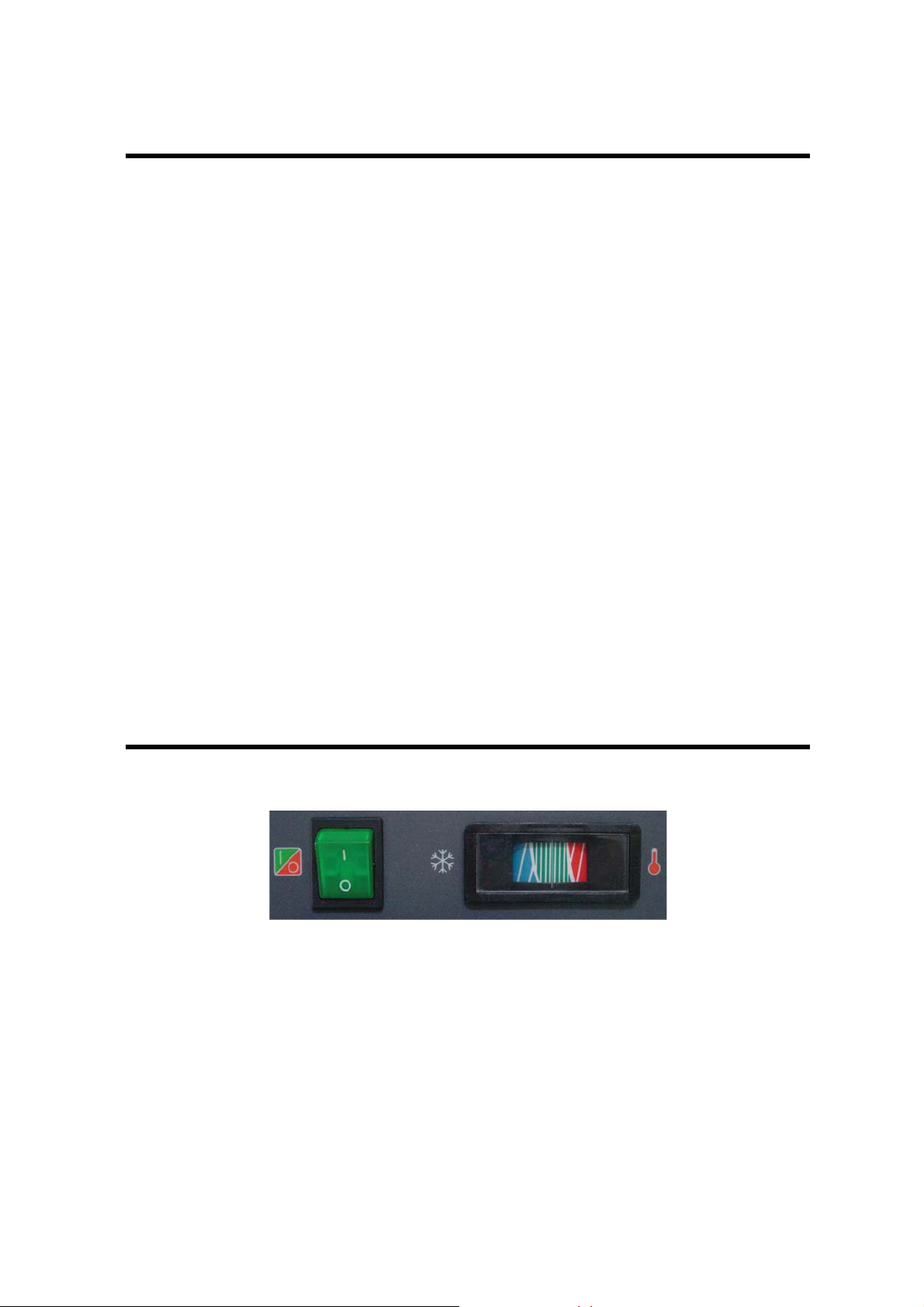
Color Indicator (HX76K~151K)
Figure 1. Color Indicator
The dryers (HX76K~151K) are equipped with a color indicator which indicates dryer
conditions as follows:
It is normal for the indicator color to be in the red zone when the dryer is first turned on
and then move to the green zone when the dryer reaches its normal operating
temperature. If this indicator is in the red zone during normal operation, turn the dryer off
to avoid compressor damage. Refer to the Field Service Guide, for additional information,
or call your local distributor.
Goodnal STP ST041 Site Services (Jemaco HXK Series Refrigerated Air Dryers HX76K to HX601K Installation
Q-Pulse Id VM409
Active 29/10/2013
Page 7 of 24
8
ELECTRONIC DRAIN VALVE
The dryers(HX76K~151K) are equipped with an electronic drain valve that automatically
discharges condensate from the dryer. The drain valve and its controls are accessible from
the left side of the dryer. The electronic drain valve has two indicators and a test button to
help verify operation. Pushing the test button causes the drain port to click open. If either
indicator fails to turn on at the proper time, refer to the maintenance section of this manual.
Drain valve operation is controlled by an electronic timer. The drain opening can be set
from 0.5 sec to 10 sec. The drain cycle can be set from 0.5 min to 45 min.
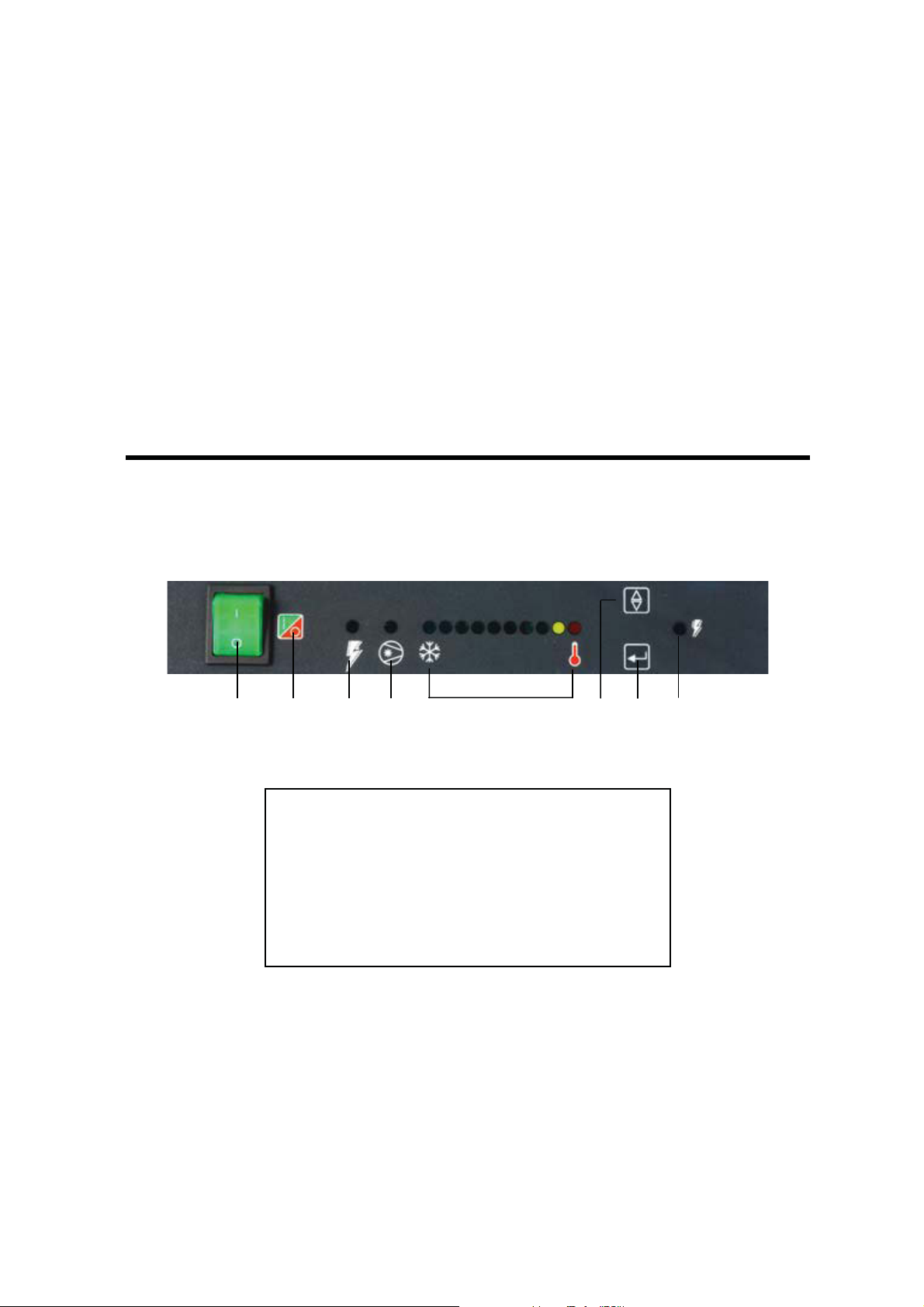
DCB, Digital Control Board (HX201K~601K)
G
The dryers(HX201K~601K) are equipped with LED type dew point indicator.
G
G
G
G
GGGGGGGGGGGGGGGGGG
G
hGGGGGGGiGGGGG
G
GjGGG
GGG
kG G G G G
GGGGGG
GGGlGGGGGGGGGGGGG
GG
Gm
G
G
GGG
G
nG G G G G oG
Figure 2. Digital Control Board
G
GA : On/off Switch
B : Switch Legend
C : Power On Light, On Time Setting Mode
D : Compressor On Light, Off Time Setting Mode
E : Dewpoint Temperature Indicator
F : Selection Button
G : Enter Button (Drain Test Button)
H : Drain On LightG
G
G
G
G
DCB has LED type dew point indicators and electronic drain valve operation time adjusting,
When the dryer is normal running, the green LED will light on. The red indicator light
indicating a need for dryer operating condition checking. If all LEDs light on, the sensor for
dew point monitor is malfunction. The automatic drain valve controls allow the period of
drain opening to the set from 0.5 sec to 9 sec and drain valve closed time to be set from
0.5 min to 15 min. When the “G” button(drain test button) is pushed, the “H” LED is on and
the drain port clicks open with a cleaning audible sound.
Goodnal STP ST041 Site Services (Jemaco HXK Series Refrigerated Air Dryers HX76K to HX601K Installation
Q-Pulse Id VM409
Active 29/10/2013
Page 8 of 24

9
AUTOMATIC DRAIN VALVE SETTING
"E" LAMP 1st 2nd 3rd 4th 5th 6th 7th 8th 9th
ON TIME
(SEC) 0.5 1 2 3 4 5 7 9
Continuous
(Drain Trap
Option)
OFF TIME
(MIN) 0.5 1 2 3 5 7 9 10 15
1. Press the “F” and “G” buttons at the same time for 3 seconds, the “C” LED will start to
flash, and the illuminated LED on the “E”(Dew Point Temperature Indicator) LED will
identify the factory setting for “On Time”. (See table)
2. Press and release the “F” button to sequence from left to right until reaching your
selection. The “Red” LED is not used.
3. To store the On time and set the Off time, press the “G” button and set as step 2.
4. Exiting the Program will cause the Timer Drain to discharge and begin a new cycle.
Note: Failure to perform step 3 within 10 seconds of completing step 2 will cause the unit
to revert back to the previous setting.
* Operating check points
Check the following on a periodic basis:
A. Green power on light is illuminated.
B. Dewpoint indicator is in green area.
C. Condensate is discharging from drain.
Electronic Drain Valve Adjustment
To minimize air losses, the drain valve control time should be adjusted to open the drain
port just long enough to discharge accumulated condensate. Set the drain valve operating
time so that only air discharges at the end of the open period. Recommended initial
settings are a 1 to 2-second drain opening and 30 seconds drain closed time (cycle). If
liquid discharges as the port is closing, set the timer for a shorter cycle or a longer opening.
Goodnal STP ST041 Site Services (Jemaco HXK Series Refrigerated Air Dryers HX76K to HX601K Installation
Q-Pulse Id VM409
Active 29/10/2013
Page 9 of 24

10
START-UP
Follow the procedure below to start your dryer. Failure to follow the prescribed start-up
procedure will invalidate the warranty. If problems arise during start-up, call your dis-
tributor.
1. Turn the dryer ON/OFF switch to OFF.
2. Turn on the main electrical power to the dryer.
3. Don’t turn the power switch to ON directly! Refer to the below.
To start dryer :
1. Turn the power switch to ON. The refrigerant compressor will turn on.
2. Confirm that condensate is discharging from the drain valve.
3. Check drain valve timing. See Electronic Drain Valve section for drain valve adjust-
ment procedure.
4. Check that the main electrical supply voltage matches the voltage specified on the
dryer data plate.
5. Check proper connection and support of compressed air lines to the dryer; check
bypass valve system, if installed.
6. Ensure adequate ventilation for air-cooled dryers.
7. Confirm that the inlet air temperature, pressure and airflow to the to the dryer meet the
specified requirements (see Table 4 & 5)
8. confirm that the condensate lines from the drain valve discharge into a collection tank
or an environmentally-approved disposal system.
9. If the refrigerant Suction Pressure Gauge is out of range, refer to the Field Service
Guide for information or contact your local distributor.
The dryer is designed to run continuously. Let the dryer run even when the demand for
compressed air is interrupted; the dryer will not freeze up.
IMPORTANT
Energize dryer for 4 hours before refrigeration compressor is started! Never use the
disconnect switch to shutdown the dryer for an extended period of time (except for
repair). Failure to follow these instructions may result in a non-warrantable compressor
failure.
Goodnal STP ST041 Site Services (Jemaco HXK Series Refrigerated Air Dryers HX76K to HX601K Installation
Q-Pulse Id VM409
Active 29/10/2013
Page 10 of 24

11
SHUTDOWN
When the dryer must be shut down for maintenance or other reasons, use the following
procedures.
If electrical repairs must be made :
1. Turn off the power switch.
2. Disconnect the main power supply.
3. Lock out and tag the power supply in accordance with OSHA requirements.
DANGER
Portions of the control circuit remain energized when the power switch is in the OFF
position. Disconnect supply power to the dryer before performing maintenance on the
electrical system.
Dismantling or working on any component of the compressed air system under
pressure may cause equipment failure and serious personal injury.
Before dismantling any part of the dryer or compressed air system, completely
vent the internal pressure to the atmosphere.
If mechanical repairs must be made, vent the internal pressure of the dryer to atmospheric
pressure. After the refrigerant compressor become cool, restart the dryer according to
the start-up instructions.
Goodnal STP ST041 Site Services (Jemaco HXK Series Refrigerated Air Dryers HX76K to HX601K Installation
Q-Pulse Id VM409
Active 29/10/2013
Page 11 of 24

12
MAINTENANCE
The dryers require little maintenance for satisfactory operation. Good performance can be
expected if the following routine maintenance steps are taken.
DANGER
Dismantling or working on any component of the compressed air system under
pressure may cause equipment failure and serious personal injury. Before dis-
mantling any part of the dryer or compressed air system, completely vent the
internal pressure to the atmosphere.
General
For continued good performance of your refrigerated dryer, all refrigeration system
maintenance should be performed by a competent refrigeration mechanic. Before correc-
tive maintenance is done during the warranty period, call your local distributor and
proceed according to instructions.
Daily
Check the operation of the electronic drain valve at least once during each 8-hour shift.
See the Field Service Guide for remedies to drain valve malfunctions. See the
ELECTRONIC DRAIN VALVE section for drain valve adjustment.
Monthly
For air-cooled condensers, it is recommended to inspect the condenser coils monthly. If
necessary, remove dirt or other particles with compressed air from an OSHA-
approved air nozzle that limits its discharge pressure to 2.1 kgf/cm².
Returns to Manufacturer
If the dryer or a component of the dryer must be returned to the manufacturer, first call
your local distributor for a return authorization number and shipping address. Your
distributor will inform you whether the dryer or only a component must be returned. Mark
the package with the return authorization number and ship freight prepaid as directed by
your local distributor.
Electronic Drain Valve Disassembly and Servicing
The valve body is mounted on the frame bottom; a hose connects the valve body to the
Goodnal STP ST041 Site Services (Jemaco HXK Series Refrigerated Air Dryers HX76K to HX601K Installation
Q-Pulse Id VM409
Active 29/10/2013
Page 12 of 24

13
heat exchanger vessel.
CAUTION
Do not disassemble drain valve timer or attempt to repair electrical parts.
Replace timer if defective.
The drain valve discharges condensate through a full-port drain opening. The valve body
may need to be cleaned under conditions of gross particulate contamination.
To disassemble the drain valve body for cleaning and other maintenance :
1. Turn power switch off.
2. Disconnect main power supply to dryer.
3. Lock out and tag power supply in accordance with OSHA requirements.
WARNING
If power supply is not disconnected before disassembly, serious personal injury
and valve damage may result.
4. Remove hoses that connect the drain valve to the drain valve strainer.
5. Remove screw and washer from front of the drain valve.
6. Remove the power supply connector and gasket(with the timer assembly if attached)
from the solenoid coil housing. Do not damage or lose the gasket.
7. Remove coil fixing nut and spring washer from top of solenoid coil housing.
8. Lift solenoid coil housing off solenoid core in valve body.
9. Unscrew solenoid core from valve body.
Once the drain valve is disassembled, the following maintenance can be performed.
1. Inspect internal parts of valve body; clean or replace as required.
2. Remove debris from valve body.
3. Wipe solenoid core components with a clean cloth or blow out debris with com-
pressed air from an OSHA-approved air nozzle that limits its discharge pressure to
2.1 kgf/cm².
4. Check that the inside part assembly is clear and solenoid coil moves freely in housing
5. If timer is attached to valve body, check electrical continuity across timer assembly.
To reassemble the drain valve, reverse the sequence of the preceding steps. After the
drain valve is reassembled, connect the main power supply to the dryer.
When the dryer is returned to service, check the drain valve for air or condensate leaks;
tighten connections as required to correct leaks. Check the drain cycle; adjust the timer
according to the procedure in the drain valve adjustment section.
Goodnal STP ST041 Site Services (Jemaco HXK Series Refrigerated Air Dryers HX76K to HX601K Installation
Q-Pulse Id VM409
Active 29/10/2013
Page 13 of 24

14
FIELD SERVICE GUIDE
Problems most frequently encountered with refrigerated dryers are water downstream of
the dryer and excessive pressure drop. Most causes can be identified and remedied by
following this guide.
DANGER
Closed refrigeration systems are potentially dangerous. Work on the refrigeration
system must be done only by a competent licensed refrigeration mechanic.
Do not release fluorocarbon refrigerants to the atmosphere. Do not discharge
liquid refrigerants into floor drains. Refrigerant vapors may accumulate in low
places. Inhalation of high concentrations may be fatal.
Do not smoke while working on the refrigeration system or when a refrigerant leak is
suspected. Burning materials may decompose refrigerants, forming toxic gas or acids
that may cause serious injury and property damage.
The refrigerant valves are adjusted at the factory with the refrigerant system operating
and no airflow through the dryer. While the dryer is operating, the suction pressure may
fluctuate slowly with changes in the refrigeration load. To determine the suction
pressure, see the Refrigerant Suction Pressure Gauge mounted on the front panel.
Goodnal STP ST041 Site Services (Jemaco HXK Series Refrigerated Air Dryers HX76K to HX601K Installation
Q-Pulse Id VM409
Active 29/10/2013
Page 14 of 24
15
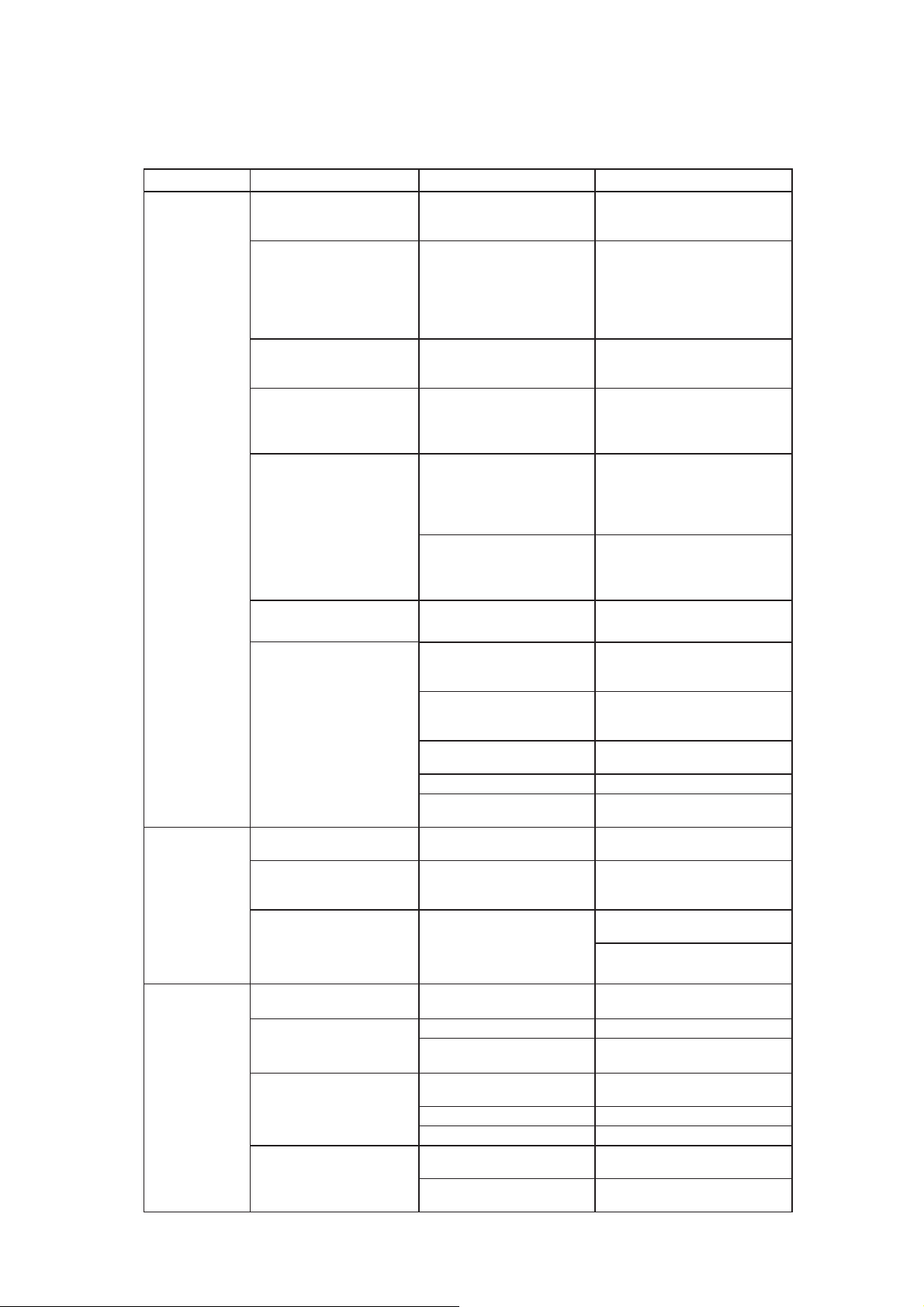
FIELD SERVICE GUIDE
PROBLEM SYMPTOM POSSIBLE CAUSE REMEDY
Water
downstream
of dryer.
No discharge from
automatic drain valves
(ADV).
ADV failure or accumula-
tion of dirt in drain valve
strainer.
Dismantle drain valve:
clean, repair or replace.
See maintenance section.
Inlet air temperature is
too high. Aftercooler malfunction.
Check aftercooler discharge
temperature. Reduce tem-
perature to 49ഒmax.;
reduce airflow if tempera-
ture is above 35ഒ.
Liquid water entering
dryer. Aftercooler drain valve
malfunction.
Dismantle aftercooler drain
valve ; clean, repair or
replace.
Excessive airflow
(may also cause high
pressure drop). Dryer improperly sized.
Check airflow and dryer
capacity(see Table 4).
Reduce airflow or resize
and replace dryer.
Compressor cuts out
on internal overload.
Inadequate ventilation of
refrigerant compressor.
Ensure adequate ventilation
of the condensing unit (see
Clearance). Motor will
restart automatically when
compressor is cool.
Leak in refrigeration
system.
Locate leak, repair and re-
charge. Motor will restart
automatically when
compressor is cool.
Compressor windings
read open or shorted. Compressor burned out. Have a refrigeration
mechanic check and replace.
The red LED light on
Inlet air temperature too
high.
Reduce aftercooler discharge
temperature to design con-
ditions(see Table 5).
Excessive airflow. Check airflow and system
capacity. Reduce airflow or
resize and replace system.
Condenser fouled or
clogged. Clean or replace condenser.
Fan motor inoperative. Replace fan motor.
High ambient temperature. Ventilate area.
See Table 5
High pressure
drop across
dryer.
Inlet air temperature
is too low. Low ambient temperature. Consult your local
distributor.
Excessive airflow(may
also cause water
downstream of dryer). Dryer improperly sized. Check airflow and dryer
capacity. Reduce airflow or
resize and replace dryer.
Dryer icing up. -
Adjust operating conditions
to meet sizing conditions.
Adjust Expansion valve to
raise suction pressure
No condensate
from automatic
drain valve
(ADV)
Valve venting. But no
condensate from valve. Accumulation of dirt in
valve strainer. Dismantle valve strainer.
Strainer clean or replace.
Valve continuously
venting.
Clogged valve orifice. Replace valve.
Short in electrical
component. Check and replace connector
or DCB assembly.
Valve not cycling. No electrical power. Check and correct power
supply and connections.
DCB malfunction. Replace DCB assembly.
Solenoid coil malfunction. Replace solenoid coil.
No response when test
button is pushed.
No electrical power. Check and correct power
supply and connections.
Burn out fuse Check solenoid coil and wiring
cable and replace fuse.
Goodnal STP ST041 Site Services (Jemaco HXK Series Refrigerated Air Dryers HX76K to HX601K Installation
Q-Pulse Id VM409
Active 29/10/2013
Page 15 of 24

16
PROBLEM SYMPTOM POSSIBLE CAUSE REMEDY
Dew Point
indicator
malfunction All LED indicator light on Sensor malfunction Replace sensor assembly
Color indicator
out of green
zone
Indicator in red zone
Inlet air temperature too
high
Reduce aftercooler discharge
temperature to design
conditions (see Table 1).
Excessive airflow Check airflow and system
capacity. Reduce airflow or
resize and replace system.
Condenser fouled or
Clogged Clean or replace condenser.
High ambient temp. Ventilate area.
Improper adjustment of
Expansion valve.
Remove cap from the exp.
valve and turn the screw until
the indicator is in the green
zone.
Indicator in blow zone Improper adjustment of
Expansion valve Adjust the exp. valve until the
indicator is in the green zone.
Table 1
SUCTION PRESSURE
REFRIGERANT WITHOUT AIRFLOW WITH AIRFLOW
R-134a (HX76K/101K) 2.2s0.1 bar 2.6s0.5 bar
R-407C (HX151K~601K) 4.2s0.1 bar 4.8s0.7 bar
Do not adjust refrigerant valves without factory authorization. Adjustments must be made
only with no airflow into the dryer.
CAUTION
Do not introduce mineral oils into the refrigeration system of the dryers.
Servicing equipment should contain NO TRACE OF MINERAL OILS.
Table 2
REFRIGERANT PRESSURE SWITCH SETTINGS
MODEL Fan Pressure Switch Setting
ON OFF
HX76K ~101K 12 ·1 bar 7 ·1 bar
HX151K~601K 21 ·1 bar 15 ·1 bar
MODEL High Pressure Switch Setting
Cut-out Cut-in
HX76K~101K 21 ·1 bar Manual Reset
Goodnal STP ST041 Site Services (Jemaco HXK Series Refrigerated Air Dryers HX76K to HX601K Installation
Q-Pulse Id VM409
Active 29/10/2013
Page 16 of 24

17
HX151K~601K 28 ·1 bar Manual Reset
Table 3
DIMENSIONS AND CONNECTION SIZES
MODEL
DIMENSIONS
( mm ) INLET-OUTLET
CONNECTIONS
(PT, Male, inch)
HWD
HX76K / 101K 601 363 861 1
HX151K 601 363 921 1
HX201K / 251K 761 443 971 2
HX351K / 426K 811 493 1151 2
HX500K 811 493 1251 2
HX601K 811 543 1321 2 1/2
Table 4
DRYER SPECIFICATIONS
MODEL
RATED
CAPACITYa
(N
/min)
POWER
SUPPLY
(V / PH/Hz)
WEIGHT
(kg)
INPUT
POWER
(kW)
REFRIGERANT
TYPEb
HX76K 2.50 230/1/50 50 0.58 R134a
HX101K 3.00 230/1/50 53 0.60 R134a
HX151K 4.92 230/1/50 58 0.87 R-407C
HX201K 6.67 230/1/50 78 1.39 R-407C
HX251K 8.00 230/1/50 85 1.58 R-407C
HX351K 10.08 230/1/50 100 2.06 R-407C
HX426K 13.33 230/1/50 112 2.61 R-407C
HX500K 15.00 230/1/50 134 2.82 R-407C
HX601K 18.02 380~420/3/50 152 3.40 R-407C
aRating conditions are 35inlet temperature, 7barg inlet pressure, 100% inlet relative humidity, 25ambient temperature
@ 50Hz.
bRefer to dryer data plate for refrigerant charge.
Table 5
DRYER OPERATING CONDITIONS
MODEL NO.
Maximum
Inlet Air
Pressure
Minimum
Inlet Air
Pressure
Maximum
Inlet Air
Temperature
Minimum
Inlet Air
Temperature
Maximum
Ambient Air
Temperature
Minimum
Ambient Air
Temperature
All models 16barg 3barg 494434
Note : Continuous operation in the above maximum and minimum operating conditions is not allowable.
Goodnal STP ST041 Site Services (Jemaco HXK Series Refrigerated Air Dryers HX76K to HX601K Installation
Q-Pulse Id VM409
Active 29/10/2013
Page 17 of 24

18
Goodnal STP ST041 Site Services (Jemaco HXK Series Refrigerated Air Dryers HX76K to HX601K Installation
Q-Pulse Id VM409
Active 29/10/2013
Page 18 of 24
19
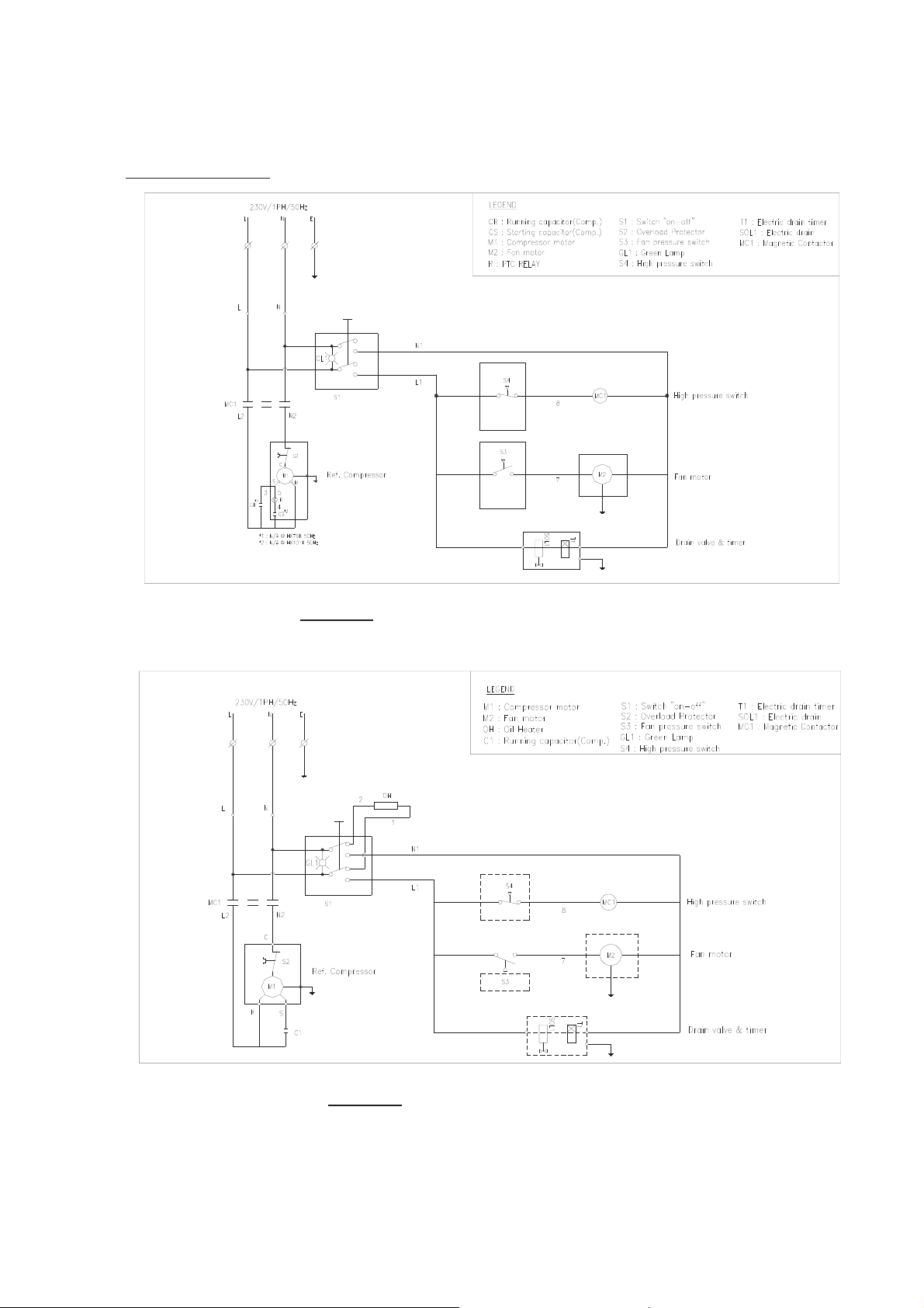
Drawings
G
lGzG
Figure 3.a Electric Schematic – HX76K / HX101KG
G
G
Figure 3.b Electric Schematic – HX151K
G
G
G
G
G
G
Goodnal STP ST041 Site Services (Jemaco HXK Series Refrigerated Air Dryers HX76K to HX601K Installation
Q-Pulse Id VM409
Active 29/10/2013
Page 19 of 24
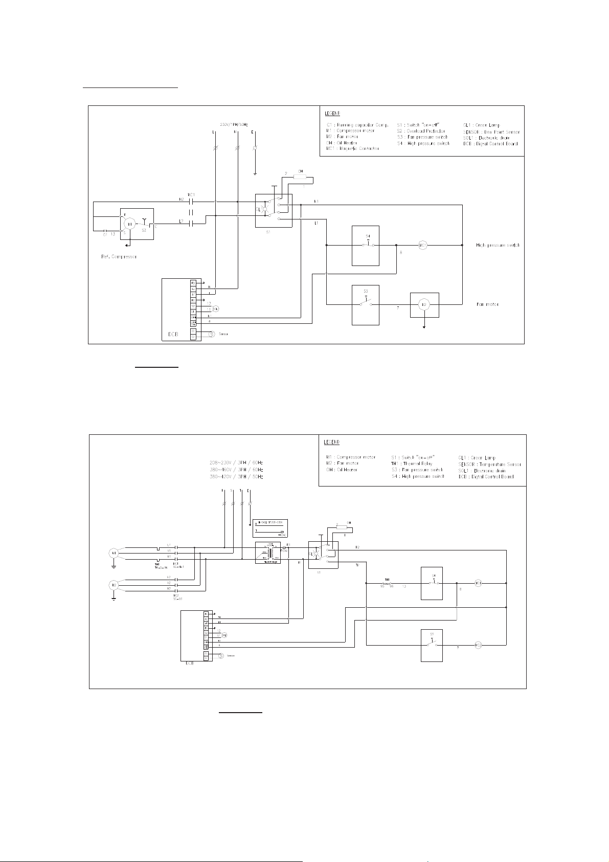
20
lGzG
G
Figure 3.c Electric Schematic - HX201K / HX251K / HX351K / HX426K / HX500KG
G
Figure 3.e Electric Schematic – HX601K
G
G
G
G
G
G
G
Goodnal STP ST041 Site Services (Jemaco HXK Series Refrigerated Air Dryers HX76K to HX601K Installation
Q-Pulse Id VM409
Active 29/10/2013
Page 20 of 24
This manual suits for next models
8
Table of contents
Other SPX Dryer manuals

Popular Dryer manuals by other brands

LG
LG SteamDryer LSDG389VS owner's manual

Whirlpool
Whirlpool LE5805XP Use and care guide

Alliance Laundry Systems
Alliance Laundry Systems ADG41F1 installation instructions

Beko
Beko DCU 9330 Installation & operating instructions and drying guidance

Miele
Miele TKR 650 WP operating instructions

Samsung
Samsung DV419AE series user manual


Bosch
Bosch WTA74201IN Installation and operating instructions

GE
GE DuraDrum GTDX200GM Dimensions and installation information

Asko
Asko TL751 XXL Training program

Whirlpool
Whirlpool W10804668A quick start guide

Siemens
Siemens WQ45G2AFDN User manual and installation instructions

Whirlpool
Whirlpool LE5721XS Use & care guide