SST NR-900S User manual

PORTABLE NONLINEAR
JUNCTION DETECTOR
“
NR-900S
”
User manual
- 2018-

PORTABLE NONLINEAR
JUNCTION DETECTOR
“
NR-900S
”
User manual
- 2018-

NR-900S Operation Manual
2
CONTENTS
1 Application.…………………………………. 5
2
NR-900S complete set……………………….
6
3
Main technical parameters…………................
7
4 Function ……………………… 8
5
Design ……………………………................
Main unit ………………………….…
Control unit ……………………………....
9
9
10
6
Accessories ……………………………..…
Imitator ………………………
Headphone
NR-900S power supply…………………….….
Charger …………………………….
11
11
12
12
13
7
NR-900S operation
Operation condition and restriction
Getting started
NR-900S workability test
NR-900S safety precaution
Detector operation in 'LISTEN' mode
Detector operation in 'SEARCH' mode
14
14
15
16
17
18
18
8 Packing 19
9 Emergency actions 20
10
Battery charging
21
11
Maintenance ……………………………….
24
12 Shipping and storage ………………… 26
13 Certificate of acceptance …………………….. 26
14 Warranty ………………………………….. 27

NR-900S Operation Manual
3
This Manual is intended
for explanation
“NR-900S” Non-linear Junction Detector
design & principle of operation
as well as directions for its use.
For proper equipment use,
study this Manual in depth.

NR-900S Operation Manual
4
The Device has an open UHF radiator
of electromagnetic energy.
In active mode it represents
a source of active interference
that could cause certain malfunction
of radio-electronic equipment
located in close proximity
It is the responsibility of the User
to comply with the corresponding
Radio Communication Regulations
of the country
where ‘NR-900S’ NLJD is being used
It is highly recommended not to aim
the device antenna to any human body or pets
from the distance less than 1 meter
NR-900S Operation Manual
5
1. APPLICATION
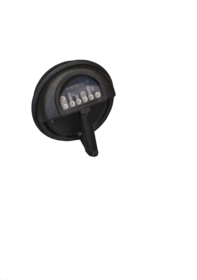
NR-900S Non-linear Junction Detector (fig. 1) is intended for
searching concealed eavesdropping devices as well as other electronic
items that contain semi-conductor elements.
NR-900S typical
targets:
−Radio-mikes.
−Microphone amplifiers.
−Wired mikes.
−Devices with IR or
ultrasonic data & control
channels.
−Video & audio
recorders.
−Electronic timers,
actuating devices of
improvised explosive
devices (IED) and etc.
NR-900S can detect typical targets in every operational mode: active,
stand-by or even switched-off.
NR-900S ensures comprehensive searching capabilities and reliable
localization of ‘bugs’ in fabric constructions, furniture and various
office or home items.
NR-900S provides its operator with an opportunity to discriminate
between industrial electronic elements and metal-to-metal contacts, so
called ‘corrosion diodes’.
NR-900S provides the unique possibility to reveal active electronic
targets at the electromagnetic background produced by various
electric devices.
Fig. 1 NR-900S

NR-900S Operation Manual
6
2. NR-900S COMPLETE SET (fig. 2)
Table 1
1
NR-900S
main unit 1
2 Carry case 1
3 Headphones 1
4 Car power adapter 1
5 Soshine SC-S1 battery charger 1
6 AC power adapter 1
7 Target imitator (test unit) 2
8 Soshine 18650 rechargeable cells 4
- Operation manual (not shown) 1
1
2
3
4
5
6
7
8
Fig.2 NR-900S Complete set

NR-900S Operation Manual
7
3. MAIN TECHNICAL PARAMETERS
Table 2
Average probing signal power in Searching
mode
not less 400 mW
Maximal probing signal pulse power in
Searching mode
not less 2 W
Maximal probing signal continuous power in
Listening mode
not less 2 W
Probing signal level -max
-mid
-min
0 dB
-6 dB
-12 dB
Receiver input signal attenuation
10 dB, 20 dB,
30 dB, 40 dB
Received signal level indication -visual
-audio
LED display
Headphones
Modulation
Pulse-amplitude
Power supply
2 x 18650 Li-ion
rechargeable cells, 3.7V
Operational condition:
Operating temperature
Storage and shipping temperature
Relative humidity (under +35°±2
°
С)
-30°С … +40°С
Minus 40°С … +50°С
93±3 %
Continuous operation time
with one set of fully charged cells
-Searchnig mode
-Listening mode
not less 3 h
not less 1 h
Weight
Device in a ready for operation state
Complete set in a standard packing
1.4 kg
8,0 kg

NR-900S Operation Manual
8
4. FUNCTION
NR-900S represents a portable tool that consists of antenna system,
transmitter and two receivers adjusted for double and triple frequency
of the transmitter’s signal.
Two operational modes are available: SEARCH and LISTEN.
In a SEARCH mode the probing signal is converted into a poly-
harmonic one on the radiated nonlinear elements (semi-conductive
items or corroded metal-oxide-metal junction) and retransmitted,
better say – scattered into ambient space.
Retransmitted 2nd & 3rd harmonics of the probing signal are received
and processed by receivers. Signals strength is indicated by LED bar-
graph display: scales 2and 3accordingly. Moreover, it is reproduced
via headphones in the form of interrupted beep-beep audio signal: 1
kHz for the 2-nd harmonic and 1.5 kHz for the 3-rd one. The audio signal
volume is proportional to the received harmonic signal level.
The receiver inputs switching as well as headphones volume control
is available from the device control panel.
NR-900S has three output levels for radiated probing signal with 6 dB
step and four levels of the receiver input signal attenuation each of 10
dB. The probing signal output level and receiver input signals
attenuation can be switched over by Control panel buttons. This info
is confirmed by LED display.
An auxiliary LISTEN mode is intended for the 2nd & 3rd harmonic
signals investigation for possible modulation imposed by internal
processes in some active electronic circuits irradiated by the probing
signal generated by NR-900S transmitter.At that, ‘active’ means the
circuit is in an operational mode carrying out its particular function.
Moreover, this can be done against the existing interference
environment.
It should be noted that Operator should be skilled enough to recognize
such features of retransmitted signals and be familiar with possible
reply of certain targets (electronic & electro-mechanical timers, clocks
or voltage transducers).

NR-900S Operation Manual
9
5. DESIGN
MAIN UNIT
NR-900S main unit (see also fig.3) represents a mono-block that
consists of antenna system and electronic unit: transmitter with two
receivers, control module and LED display - indication panel.
NR-900S antenna system consists of two directional antennas
(transmitting and receiving) with linear polarization attached to
reflector and are covered by a plastic dome. Main lobes of antennas
radiation pattern are oriented along their geometrical axis..
Meanwhile, this fact forces an Operator to rotate the antenna
module at least ±90
°
around its imaginary axis passing
perpendicularly to antenna front surface for assured possible target
investigation.
5
1
2
3
4
Fig. 3. NR-900S
ready for operation.
1-main unit, 2- control unit with
display, 3
-headphone, 4 – handle, 5 - socket
NR-900S Operation Manual
10
On the back side of the main unit the Control unit with a handle and
operation display are placed.
NR-900S is made in dust- and waterproof version and has robust
enclosure, ensuring safe operation within wide range of temperatures.
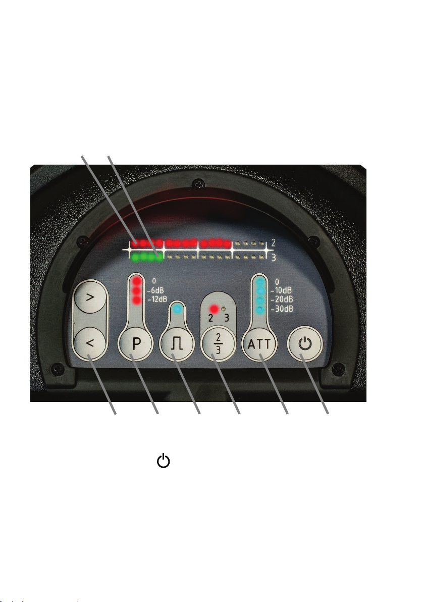
CONTROL UNIT
1. Power ON/OFF button .
2. Receiver sensitivity control (ATT - attenuator) with 4 blue LEDs
indication (0, -10 dB, -20 Db, -30 dB)
3. Headphone commutation button with LED confirmation ‘2/3’ –
what receiver is coupled to the headphone: 2-nd or 3-rd one.
Fig.4 NR-900S Control unit with display
1
2
3
4
5
6
7
8

NR-900S Operation Manual
11
4. Operational mode switch Search Listen with LED
confirmation (blue LED corresponds to Searching mode).
5. Probing signal output power switch Pwith LED confirmation:
0, -6 dB, -12 dB. If the LEDs are dead - the transmitter is off.).
6. Headphone volume control buttons <, >for audio signal
adjustment.
7. 2nd harmonic bar-graph indicator (16 red LEDs).
8. 3rd harmonic bar-graph indicator (16 green LEDs).
NOTE: Both signal level bar-graph displays are divided to 4
equal sections with 4 LEDs in each.
Every LED corresponds to 2.5 dB, thus every section matches to
10 dB of a probing signal level harmonic - 2-nd or 3-rd.
The battery compartment for two Li-Ion Soshine 18650 rechargeable
cells is located inside an ergonomic handle
(see pos. 4 at the fig. 3).
Its bottom cover is supplied with rotating lock.
The jack for headphone connection is on the left side of the
device body (pos. 4 at the fig.3).
6. ACCESSORIES
IMITATOR
Target Imitator (test unit)
is intended for NR-900S
workability control (fig.
9). Imitator represents
high-frequency semi-
conductor diode in a solid
plastic body.
Fig. 9 NR-900S Imitator (test unit)

NR-900S Operation Manual
12
HEADPHONE
Headphone allows Operator
not only to confirm the target
response but also to identify it
in a certain way judging by
the typical audio reply signal
from an active device.
NR-900S POWER SUPPLY
NR-900S power supple is provided by the battery of two Li-Ion
rechargeable cells -18650 form factor (fig. 11). Cell rated voltage is
3.7V with 2800mAh
capacity.
For battery charging
Soshine SC-S1 max
Charger (supplied) is
used.
NOTE: After battery
discharge below 5,7 V :
the LED starts
blinking.
In this case replace the
battery as soon as
possible.
Fig. 11 Soshine 18650 cells
Fig. 10 Headphone
NR-900S Operation Manual
13
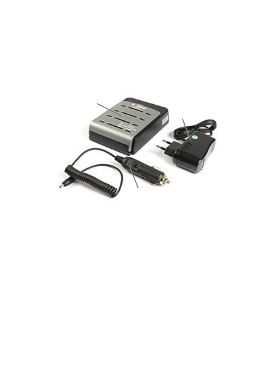
CHARGER
Soshine SC-S1 max Charger (fig. 12) is intended for rechargeable
cells charging. The battery charging is performed in an automatic
mode and does not need any operator’s assistance.
NOTE:
Soshine AC adapter (fig. 12, pos. 3) allows to charge the battery from
the mains 100 – 240 V, 50/60 Hz.
In case of another AC adapter in a supplied set – check its parameters
referring the label on AC adapter body.
Soshine DС12V car adapter (fig.12, pos. 2) is intended for battery
charging from the motocar 12V DC net.
1
2
3
Fig. 12 NR-900S standard Charger complete set.
1 – Soshine SC-S1 max charger unit
2 – Soshine DС12V car adapter
3 – Soshine AC power adapter

NR-900S Operation Manual
14
7. NR-900S OPERATION
OPERATION CONDITION AND RESTRICTIONS
After long-term equipment exposure to a low temperature keep the
device packed in a standard packing at least 2 hours for evening up
its temperature with the environment.
Operating NR-900S keep corresponding safety measures.
Safety precautions for open RF emitters:
-Do not direct NR-900S antenna to the human eyes from the
distance less than one meter.
-Avoid prolonged presence of personnel in a main lobe
of NR-900S antenna’ diagram.
NOTE: Probing signal power density at the distance of 1 meter
along the maximum of NR-900S antenna directional radiation
pattern does not exceed Russian State Standard 12.1.006-84
(Russian State Sanitary Norm) for UHF-equipment
serviceman under continuous 8-hours operation.
Keep NR-900S detector from mechanic damages and protected its
connectors from moisture and dirt.
Packing NR-900S into the case use packing layout for reference
Wrong packing can lead to mechanic damage and breakdown of the
equipment.

NR-900S Operation Manual
15
GETTING STARTED
Take NR-900S components out of standard packing.
Insert two fresh rechargeable cells (fig. 12) into the battery
compartment keeping the cells polarity specified on the compartment
side wall .
- Close the battery compartment cover and lock it.
- Plug headphones to the jack (5) on a side wall of Control unit (fig.3).
- Press button to switch on the device.
At that the following operational modes are initiated:
-the device is in Searching mode confirmed by blue LED;
-the probing signal power is minimal (confirmed by red LED –
‘12dB’ at the control panel);
-the receiver sensitivity is also minimal – the input signal
attenuation 30 Db activated (confirmed by one blue LED ‘-30 dB’
at the ATT scale of control unit);
-the headphone is coupled to the 2-nd harmonic receiver output
(confirmed by red LED ‘2’ at the scale ‘2/3’ of control unit);
-the volume control is in the ‘mid’ position.
Fig. 13 Inserting
rechargeable cells
Watch cells polarity

NR-900S Operation Manual
16
NR-900S WORKABILITY TEST
- Use button ATT to set maximal sensitivity of the receivers (every
LED at the ATT scale are ON).
- Use button ‘P’ to adjust maximal output power of the probing
signal (all 3 red LEDs are ON).
- Put on the headphone.
- Analyze the interference environment aiming antenna system to
different directions.
- In case of noticeable interference antenna unit should be oriented
so that the interference signal is not heard in the headphones.
- Make sure that no 2-nd , no 3-rd harmonic reply is indicated by
corresponding LEDs or audio signals (use 2/3 button to check this).
- Use Pbutton to adjust the device minimum output.
- Place the test
unit vertically 0.4 m
in front of the device
antenna unit.
- The interrupted audio signal should be heard in the headphone, as
well as 6 red & 6 green LEDs shine at the corresponding bar-graph
scales.
- Altering the target imitator location in front of antenna system try
to obtain the full 2nd harmonic LED-scale indication.
- Use 2/3 button to switch headphone for 3-rd harmonic reply and
check the device operation in this mode (this manipulation should
be confirmed by audio signal of a higher tone)
0.4 m
Imitator
Fig. 14 NR-900S operation test
by means of standard imitator

NR-900S Operation Manual
17
- Keeping the Test-unit position try to alter the device sensitivity and
control its corresponding indication.
- Moreover, boost the device output by means of ‘P’ button and be
convinced of a corresponding display indication.
The device is fully functional and ready for operation.
USEFUL HINT:
An original schematic design enables to supply NR-900S
operator with an outstanding feature: searching for illegal
electronics the NLJD Operator takes notice of an audio
alarm signal (tiny beep-beep) prior to custom LED
indication.
This point is very important when an operator (a sapper) is
searching for such a dangerous target like IED, and all his
attention (and eyesight) is concentrated on the environment
that might conceal a mine (not blinking lights on display).
NR-900S SAFETY PRECAUTIONS
NR-900s Detector represents a high sensitive radio-electronic device.
Getting started remove from your pockets and outfit any items that
contains semi-conductive components.
Searching for radio-electronic devices that are in active mode, please,
take into account that pulse EM signals radiated by Detector can affect
the function of these devices.
Searching for improvised explosive devices (IED), start from the
position not less than 10 meters from the area to be inspected.
Keep antenna head at least one meter from an article or surface
under control.
To avoid accidental triggering of a target, reduce output power to its
minimum level immediately after receiving a steady reply.

NR-900S Operation Manual
18
DETECTOR OPERATION IN ‘LISTEN’ MODE
Switch over Detector to the ‘LISTEN’ mode: LED is off.
Direct the device to the possible target position.
Control the audio signal in the headphone switching the button 2/3 to
obtain the 2-nd and the 3-rd harmonic reply. The presence of a certain
audio modulation in the reply signal indicates that the target is in an
active mode. Judging by the typical signal features try to identify the
device as a part of a target.
And if no reply signal was detected try to increase the receiver’s
sensitivity by ‘ATT’button as well as boost the transmitter output by
‘P’ button and only after that (in case of no reply) start moving in a
chosen direction.
DETECTOR OPERATION IN ‘SEARCH’ MODE
-Switch on Detector and carry out its workability test referring p.16
of this Manual.
-Switch over Detector to the ‘SEARCH’ mode (LED is on).
-Push ATT button to adjust maximal receiver sensitivity.
-Direct Antenna head to the questioned area starting from the close
proximity. Check the ambience scanning it from left to right step-by-step
expanding the zone of inspection tilting-up Antenna module.
-If there is no visual indication on 2nd and/or 3rd bar-graph display
and no audio signal in the headphones – push ‘P’ button to increase
probing signal level to maximal if necessary.
-When the reply signal appears, identify the signal source (target)
location by the peak level of the 2nd &3rd harmonic display and the
maximal sound level in the headphones. If necessary decrease the
receivers sensitivity by means of button ATT.
-Start moving towards the target adjusting (if necessary) probing
signal level and receivers sensitivity by means of P and ATT
buttons.

NR-900S Operation Manual
19
NOTE: The practical probing signal level and receivers sensitivity
are defined by the interference environment right on spot of the
operation. There might be certain outside signals on the receivers
adjustment frequencies and/or the presence of nonlinear reflectors,
that cannot be removed from the examination area.
-Comparing the 2nd and 3rd harmonics levels make the conclusion
concerning the possible nature of the target revealed.
NOTE: If the 2nd harmonic level is higher than the 3rd one more than
by 10 dB (difference is more than 4 LEDs) - the target is likely to be
an electronic device.
On the contrary, if the 3rd harmonics level excesses 2nd one more than
by 10 dB, the signal source is likely to be an object with metal-to-metal
contacts.
NOTE: If the target reply at the 2nd harmonic is about
25±5 dB (from 8 to 12 red LEDs shining at the scale)
- don’t move closer to the target and reduce the probing
signal output. Subsequent target investigation should be
done under low device output.
-When the target location is determined switch off Detector and
follow the Standing Instruction handling with the revealed target.
8. PACKING
By the end of practical operation do the following:
−Switch off the Detector.
−Remove cells from the battery compartment.
−Unplug headphones from the Main unit.
−Check Detector’s components condition, wipe them with rag if
necessary.
−Cover all sockets with corresponding rubber caps.
−Put Detector’s components into the carry case and fasten it.
Table of contents


