Stadt GLACIER User manual
Rev1/Nov ‘98
1
~ The future in heating and cooling ~
GLACIER
EVAPORATIVE
COOLERS
OPERATING GUIDE

Rev1/Nov ‘98
2
How do they work?
Fresh outside air is drawn into the unit through a series of wet filter pads. This causes
evaporation to take place and the resulting air eing lown through the duct work is filtered and cooled.
The resulting cool air is then dispersed into each room (to e cooled) through an outlet at a rate pre-
determined y your contractor at the time of sale. This rate of air is governed y the outlet size and the
duct layout. Adequate air flow is essential for optimum operation of evaporative cooling and it is
necessary to exhaust air via open windows or doors. It is advisa le that each room that has an outlet
has the window slightly open. This allows the cool air to flow from the outlet across the room and out
via open windows. In some circumstances you can channel the air through the house y leaving a
door/window open at one end of the house, however you should consult your contractor for the est
way to do this.
Humidity
Evaporative coolers are particularly suited for dry regions. If outside air is particularly humid
then the est result from your cooling unit may e to run the unit on fan mode only (without operating
the water pump). This is done y pressing the fan only utton and adjusting the fan speed to your
desired setting via the step utton.
Electronic Control
The low voltage electronic control is designed to provide automatic and manual operation. It
provides the following features:
•Automatic Fan Speed Control in “COOL” Mode
•Manual Fan Speed Override for “COOL” Mode
•Fan Only Mode for Ventilation
•Timer Control for automatic switch off
Note that all commands use a delay of approximately ten seconds. For example, having
chosen a particular fan speed a change will not e noticea le for 10 seconds.
Rev1/Nov ‘98
3
Operation
This section explains how to operate your Stadt Glacier evaporative cooler, and the functions
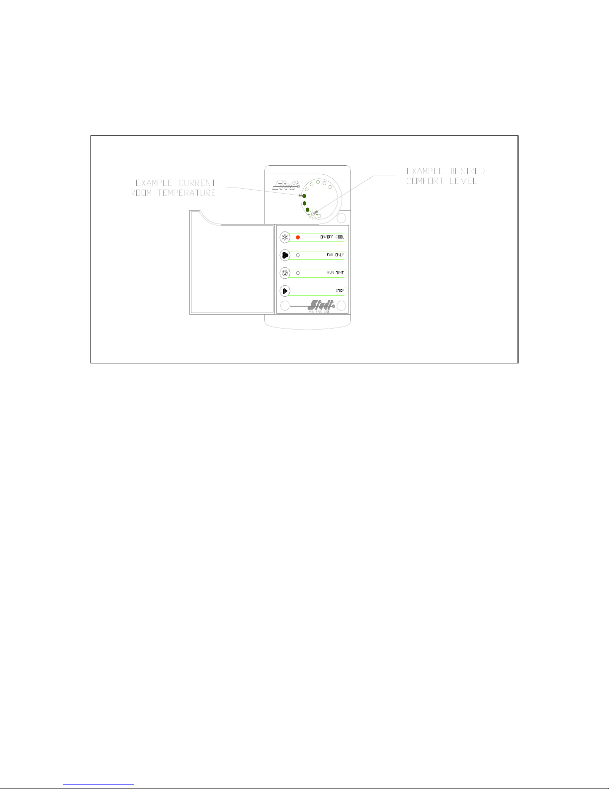
of each of the uttons featured on the evaporative cooling wall controller. Figure 1 shows the controller
for your evaporative cooler. It features four uttons which are used to control the operation of the unit,
and an array of lights which are used to display the operation of the unit.
Figure 1. Wall controller showing automatic cooling operation.
Step Button
As explained throughout these instructions the “STEP” utton is used to increment various
features such as the comfort level, fan speed or the time after which the unit will turn off.
On/Off Cool Button (Automatic Mode)
Press the utton marked “ON/OFF COOL” once and the sequence of events listed elow will
occur automatically.
1. A range of lights will appear on the display. The top light will indicate the current room
temperature. The lower flashing light will indicate your required comfort level.
2. Each press of the “STEP” utton will change your required comfort level. For example at comfort
level two (2) the unit will cool less than comfort level one (1).
3. Your unit will not operate the fan immediately. Should the unit e fitted with a dump valve the unit
will fill the water sump. Should the unit not e fitted with a dump valve the sump will already e filled
with water.
4. Next, the pump will move water over the filter pads (pre-wetting) thus saturating your pads so the
first urst of air will e cool.
5. After the pre-wet cycle is finished the pump will continue to operate and the fan will come on
automatically. The fan will adjust its own speed according to the difference in temperature etween
that inside your house and your selected comfort level.
6. As the room temperature nears the preset comfort level the fan of the unit will automatically slow
down and the num er of lights will decrease, indicating the lowering temperature. As your house
temperature rises the fan speed will automatically increase to reduce the temperature to your
required comfort level or as close as possi le. Note that the desired comfort level is not always
achieva le as the humidity of the outside environment is varia le.
7. To turn your unit off simply press the “ON/OFF COOL” utton once again.

Rev1/Nov ‘98
4
8. At each press of the “STEP” utton the lower flashing light will move in a clockwise direction.
If the mains power to the unit has not een interrupted the next time the “ON/OFF COOL”
utton is activated the comfort level setting will e as last programmed.
If the mains power has een interrupted the comfort level setting will revert ack to the lowest
setting when automatic cooling is next activated.
On/Off Cool Button (Manual Mode)
Whilst in the automatic mode the fan selects its own speed, although at times you may wish to
manually adjust the fan speed whilst still in the cooling mode. You can do this y pressing the “FAN
ONLY” utton after pressing the “ON/OFF COOL” utton. Pressing the “STEP” utton will increase the
fan speed to your desired level. In this mode the display changes to show a continuous line of lights
indicating the manually set fan speed and a light eside the ON/OFF COOL utton and a light eside
the “FAN ONLY” utton. This overrides your automatic comfort level and the fan will operate at your
speed setting until you further adjust the speed setting or turn the unit off. Should you wish to return to
automatic cooling operation press the “FAN ONLY” utton once more.
Figure 2. Wall controller showing manual fan operation.
Fan Only Button
To operate the fan only press the “FAN” utton once, then press the “STEP” utton to select
the desired fan speed. This speed will e displayed y a solid series of lights. The speed increases as
you press the “STEP” utton. The lights will illuminate in a clockwise direction, as shown in Figure 3.
The operation of the fan only is normally used to move fresh air through the house or on particularly
humid days.

Rev1/Nov ‘98
5
Figure 3. Wall controller showing changes to fan operation.
Run Time Button
This utton allows you to preset the time at which your cooler turns on or off.
If the unit is operating and you press the “RUN TIME” utton all the light indicators will go
lank. If you press the “STEP” utton the lowermost light will e illuminated. This indicates that the
unit will turn off in one (1) hour (the off time). Each su sequent press of the “STEP” utton delays the
unit turning off y one more hour. This will e indicated y the light moving clockwise around the dial
as shown in Figure 4. If having reached the ten (10) hour mark and the “STEP” utton is pressed
again the off time will return to zero (0). If the “RUN TIME” utton is pressed again the display will
return to the state it was in efore activating the “RUN TIME” utton for the first time, i.e. it will return to
that shown in Figure 1 or Figure 2, depending on which mode the unit is operating. The light eside
the “RUN TIME” utton will now flash, indicating the num er of hours left efore the unit turns off. At ½
an hour to the turn on or turn off time the small red light eside the “RUN TIME” utton will flash rapidly,
until the unit either turns on or off.
If the unit is not operating and the “RUN TIME” utton is pressed this will set the time at which
the unit will turn on. If you press the “STEP” utton the lowermost light will e illuminated. This
indicates that the unit will turn on in one (1) hour, the “on time”. Each su sequent press of the “STEP”
utton delays the unit turning on y one more hour. This will e indicated y the light moving clockwise
around the dial as shown in Figure 4. Unlike in Figure 4 the lights eside either of the “ON/OFF COOL”
or “FAN ONLY” utton will not e illuminated, as the unit is not currently operating. Again, if having
reached the ten (10) hour mark and the “STEP” utton is pressed again the on time will return to zero
(0). Pressing the “RUN TIME” utton a second time will clear the main display of lights. The light
eside the “RUN TIME” utton will now flash, indicating the num er of hours left efore the unit turns
on. Having counted down to the on time the unit will automatically turn on and select the lowest
temperature setting which also automatically sets the fan speed.

Rev1/Nov ‘98
6
Figure 4. Wall controller showing changes in run time.
Figure 5. Wall controller showing countdown to "on time".

Rev1/Nov ‘98
7
Maintenance
Regular maintenance is essential for ensuring that your evaporative cooler operates at
maximum efficiency and comfort levels. To ensure that your evaporative cooler remains in good
working condition for many years it should e thoroughly serviced every year. This service should e
performed at the eginning and end of each cooling season.
FOR S RVIC CALL 03 9800 2409
Table of contents
Popular Freezer manuals by other brands


Zanussi
Zanussi ZRB36104WA user manual

Electrolux
Electrolux ST265 user manual

Miele
Miele FN 35402 i Operating and installation instructions

Silver King
Silver King SKFMW34-ELUS1 Technical manual and replacement parts list

Beko
Beko TZDA 568 FW Installation & operating instructions

Haier
Haier Chest Freezer Instructions for use