Stalgast 880173 User manual

Freezer/cooling cabinet
MODEL: 880173, 880174, 880175, 880176, 880177,
880400, 880401, 880402, 880405, 880406, 880600, 880601,
880602, 880603, 880604
USER MANUAL
Stalgast sp. z o.o. ul. Staniewicka 5 03-310 Warszawa
v8.0 - 03.2018

- 2 -
TABLE OF CONTENTS
1. SAFETY INSTRUCTIONS ....................................................................................................... 3
2. PURPOSE OF THE DEVICE .................................................................................................... 3
3. TECHNICAL DATA .................................................................................................................. 3
4. ASSEMBLY ............................................................................................................................... 3
4.1. Device setting ...................................................................................................................................................... 3
4.2. Connection to the power supply source............................................................................................................ 4
5. CONTROL PANEL OPTION 1 ................................................................................................ 4
5.1. Main functions ..................................................................................................................................................... 4
5.2. Technical parameterse: ...................................................................................................................................... 4
5.3. Description of the parameters........................................................................................................................... 5
5.4. Button functions ................................................................................................................................................. 5
5.5. Control of compressor operation and defrost function.................................................................................... 6
5.6. Error messages.................................................................................................................................................... 6
6. CONTROL PANEL OPTION 2 ................................................................................................ 6
6.1. Description of indicator ...................................................................................................................................... 7
6.2. How to check the duration of the alarm and the minimum and maximum temperatures............................ 7
6.3. Deleting a saved alarm - recurring .................................................................................................................... 7
6.4. How to view the setpoint ................................................................................................................................... 7
6.5. Changes in settings ............................................................................................................................................. 7
6.6. Start manual defrost .......................................................................................................................................... 7
6.7. Changing the value of the parameters............................................................................................................... 7
6.8. Locking the keyboard ......................................................................................................................................... 7
6.9. Unlocking the keyboard...................................................................................................................................... 7
6.10. Continuous cycle ............................................................................................................................................... 8
6.11. Alarms ................................................................................................................................................................ 8
7. CLEANING AND MAINTENANCE ........................................................................................ 8
8. PROCEDURE IN THE EVENT OF POWER FAILURE............................................................. 8
8.1. Starting the device in the case of going above the alarm temperature value................................................. 8
8.2. Starting the device in the case of going below the alarm temperature value ................................................ 8
9. DISPOSING OF USED EQUIPMENT...................................................................................... 8
10. WARR ANTY............................................................................................................................. 9

- 3 -
Thank you for purchasing our product. Please carefully read this instruction manual before rst use.
Reproduction of this manual without the consent of the manufacturer is prohibited.
The photos and drawings are illustrative and may differ from the purchased device.
CAUTION: The manual should be kept in a safe place, available to the staff. The manufacturer reserves the right to change the
technical parameters of the device without prior notice.
1. SAFETY INSTRUCTIONS
•Incorrect operation and improper use can cause serious damage to the device or injuries to persons.
•The device should only be used for the purpose for which it was designed.
•The manufacturer assumes no liability for any damages caused by incorrect operation and improper use of the device.
•During operation the device and the power cable plug must be protected against contact with water or other liquids. If the
device accidentally falls into water, it is necessary to immediately pull the plug out from the socket, and then commission
the inspection of the device by a professional.
Failure to follow this instruction may cause life-threatening situations.
•Never open the housing of the device by yourself.
•Do not stick any items into the housing of the device. Do not touch the power cord plug with wet hands.
•Regularly inspect the condition of the plug and the cable. In the event any damage to the plug or the
•cable is found, it should be repaired in an authorized repair point.
•In case the device falls or is damaged in any other way, before further use it is always necessary for it to
•be inspected and possibly repaired at a specialized repair point.
•Never try to repair the device by yourself - it could lead to life-threatening situations.
•Protect the power cable from contact with sharp or hot objects and keep it away from open ames. If you want to discon-
nect the device from the electrical socket, always grab it by the plug and never pull by the cord.
•Secure the cable (or its extension cord) to ensure that no one pulls it from the socket by mistake and that no one trips
over the cable. Control the operation of the device during use.
•It is prohibited for the device to be used by minors, people with physical or mental disabilities and people with impaired
mobility, as well as persons without the appropriate experience and knowledge regarding the proper use of the device.
Such persons can operate the device only under the supervision of a person responsible for safety.
•If the device is not currently in use or is cleaned, it is necessary to always unplug it from the power source by removing the
plug from the socket.
•Caution: If the plug of the power cord is connected to the electrical socket, the device remains energized. Switch the
device off before pulling the plug from the socket.
•Never pull the device by the power cord.
2. PURPOSE OF THE DEVICE
• Refrigeration tables are designed for short-term storage of pre-chilled CHILLED food products.
• Freezer tables are designed for storage of pre-frozen food products.
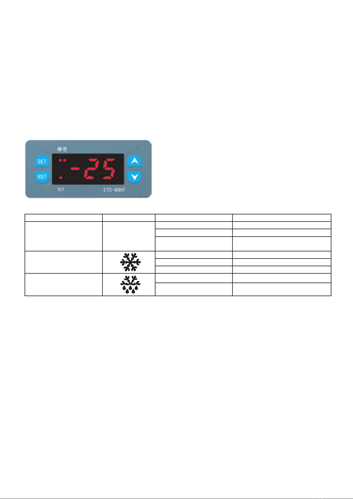
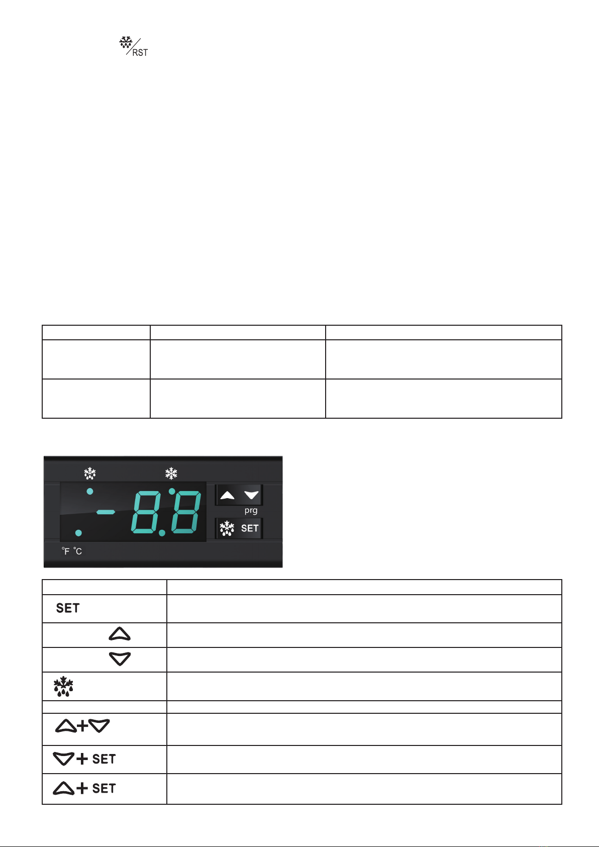
3. TECHNICAL DATA
Model 8 80173,
88 0175
88 0174,
88 0176
88 0177 880400,
880405
880402 880401,
880406
880600,
880602
880601,
880603
880604
Power supply 230 V / 50 Hz
Power 0.09 kW 0.11 kW 0.12 kW 0.11 kW 0.19 kW 0.11 K W 0.19 kW 0.35 kW 0.185 kW
Temperature
range
0 ~+1 0 -10 ~ -25 +2/+8 0 ~+10 0 ~+1 0 -10 ~ -25 0 ~ +10 -10 ~ -25 +2 /+8
Dimensions
(WxDxH)
600x600x850
mm
600x600x850
mm
600x585x855
mm
600x600x1850
mm
600x600x1850
mm
600x600x1850
mm
775x695x1900
mm
775x695x1890
mm
780x695x1895
mm
Capacity 130 l 120 l 129 l 350 l 350 l 350 l 600 l 600 l 620 l
Coolant/
quantity
R134a R134a R134a R134a R134a R134a R134a R134a R134a
100 g 130 g 100 g 160 g 160 g 160 g 215 g 250 g 215 g
Climate class 4 4 4 4 4 4 4 4 4
4. ASSEMBLY
4.1. Device setting
UThe device should be placed in a dry, adequately ventilated room. In order to ensure proper operation of the device, do not
place the device near heat sources and do not expose it to direct sunlight. The optimal temperature range in the room where
the device operates is within the following limits:
+16°C to +35°C.

- 4 -
If the device is installed in a room with high humidity, you may need to buy an additional tray for condensed water.
Avoid placing the device in rooms with a high chlorine content and acids in the air (e.g. swimming pools), as this may cause
corrosion of the stainless steel surface.
The device is intended for installation as a free-standing unit by the wall.
Important: The device should be placed in an area ensuring proper ventilation and free air ow around it. The correct
distance from the rear panel of the device is ensured by special components located on the back of the device..
4.2. Connection to the power supply source
The device should be connected to a source of alternating current.
Before connecting the device to the electric network, make sure that the voltage and frequency at the location where the
device is installed are consistent with the values indicated on the name plate.
The power source must be grounded and equipped with a residual-current circuit breaker in accordance with the applicable
laws
5. CONTROL PANEL OPTION 1
Descr:
Indicator lamp Symbol Status Meaning
Settings light SET
Light on Setting parameters
Light off Measurement and control
Flashing light Checking parameters, entering the
password
Cooling control light
Light on Cooling
Light off Cooling stop
Flashing light Cooling delay
Defrost light
Light on Defrosting
Light off Defrosting stop
5.1. Main functions
•Interior temperature control: Defrost control in accordance with the value set + temperature difference value.
•Defrost control: defrosting when the compressor stops, defrosting temperature control through dening the defrosting
time + defrosting end temperature.
•Two-channel temperature sensor system: Interior temperature sensor, evaporator sensor (the user decides whether to
activate this sensor or not).
•Menu locked with a password.
5.2. Technical parameterse:
•Temperature measurement in the range: -40°C ~+70°C Display with an accuracy of up to 1°C
•Accuracy: ±1°C (at a temperature between -40°C ~+50°C); ± 2°C (at a temperature between -50°C ~+70°C). Tempe-
rature range: -40°C ~+50°C
•Power supply: 220VAC±10%, 50/60Hz Power consumption: <3W
•Working conditions:
•cooling: 30A/240VAC, always active, (only needs single-phase supply with maximum load 1.5HP(240VAC)
•defrosting: defrosting in a natural way (without engaging power)
•Dimensions of the installation opening: 71 x 29 (mm)
•Appliance dimensions: 75 x 34.5 x 58 (mm)
•Ambient temperature during operation: 0°C ~+60°C
•Storage temperature: -30°C ~+75°C
•Relative humidity: 20%~85% (no condensate)

- 5 -
5.3. Description of the parameters
Code Function Setup Range Default value Unit
F01 Menu password
00-99
00: canceling the
button lock function
55 NONE
F02 Setting the temperature value -40 ~+50 2 °C
F03 Setting the temperature
difference 1 – 15 4 °C
F04 Delay of compressor
activation time 1 – 15 3 min.
F05 Interior temperature
calibration -5 ~ +5 0 °C
F06 Maximum defrosting time 1 – 60 20 min.
F07 Defrosting cycle 1 – 30 units 12 1 unit = 30 min.
F08 Defrost end temperature -20 ~+30 7°C
F09 Activation or lack of activation
of the evaporator sensor
00: inactive
01: active 1NONE
5.4. Button functions
Button Function
SET Press to enter the password; Parameter setting mode; Switching between menu and parameter modes
Press to check the value of the set temperature; Choosing menu function; Changing parameter and
password settings
Press to check the value of the evaporator sensor; Choosing menu function; Changing parameter and
password settings
Exit from the parameter setting mode; Manual defrosting activation or deactivation
Temperature measurement and control mode
•Press the “SET” button and hold it for 3 seconds
In case the keypad password has been set to „0”, the setting indicator lights up, the display shows the „F1” code from the
menu, the password is not conrmed and you must directly enter the menu mode to set the parameter
If the keypad password has not been set to „0”, the control light ashes and the display shows„00”, press the button „
and „ ”, to enter the password, then press the „SET” button to conrm the password. If the password is compatible,
the system will go to the settings menu. If the password does not match, the control light will go out and the system will return
to normal measurement and temperature control.
Checking parameter settings:
Press the button „ ”. The „SET” setting indicator light ashes and the display shows the set value temperature.
Press the button „ ”. The „SET” setting indicator light ashes and the display shows the temperature value evaporator
sensor.
After entering the settings menu, press „ ” and the „ ”, to select the desired menu function (from F01 to F09)
After selecting the desired menu function, press the „SET” button to set the parameter, press „ ” and „ ” ” and
select the desired parameter value, then press the „SET” button again to return to the function selection from the menu.
In the settings selection mode, press „ ” l” or do not press any buttons for 30 seconds, the system will save the set
parameter values and exit the parameter setting mode..

- 6 -
Press the button „ ”and hold for 3 seconds to manually activate or deactivate defrosting.
5.5. Control of compressor operation and defrost function
•Compressor:
The compressor will be activated when the time of its activation delay has elapsed if the temperature sensor shows that it is
higher than the „set temperature value + value of the temperature difference”.
When the temperature sensor shows that it is lower than the set temperature value, the compressor will stop working.
•Defrosting:
The system will start defrosting in accordance with the preset defrost cycle, or when defrost is activated manually. If the
evaporator sensor has been activated and the temperature detected by it is higher than the defrosting end temperature, it is
not possible to activate the defrost function manually.
Defrosting will end when the temperature detected by the evaporator sensor reaches a value equal to the preset value of the
defrost end temperature, or when the defrosting time has elapsed, or when defrosting is turned off manually
If the evaporator sensor has not been activated or if an error occurs, the defrosting will be interrupted when the set defrosting
time has elapsed, or if the defrost is deactivated manually.
5.6. Error messages
Prompt Cause Effect
E1 Chamber sensor error Have the maintenance service replace the chamber
sensor. After removing the fault, the system will
recalculate the compressor activation delay time.
E2 Evaporator sensor error
The defrost end temperature is
incorrect
Have the maintenance service replace the evaporator
sensor.
6. CONTROL PANEL OPTION 2
Button Function
it is used to display the setting; in the programming cycle it serves to select a parameter or
conrm an operation
Up arrow
using this arrow, you can display the last alarm; in the programming cycle it is used to scroll
the parameters or to increase the displayed value
Down arrow
The down arrow is used to display the last alarm; in the programming cycle it allows scrolling
through the parameters or decreasing the displayed settings
DEF
This button is used to start the defrosting process manually.
Button combinations
is used to lock and unlock the keyboard
It is used to enter the programming process
back to the chamber temperature display

- 7 -
6.1. Description of indicator
On compressor activated
Flashes the programming phase has been started
On defrosting activated
Flashes Programming phase, dripping
oF
oC
On Degrees Fahrenheit
Degrees Celsius
6.2. How to check the duration of the alarm and the minimum and maximum temperatures
If the alarm symbol appears in the display; to view the type of alarm, min (max) temperature, alarm duration, proceed as
follows.
1. Press the up or down arrow button
2. The display shows the following „HAL” message for high temperature alarm, or „LAL” for low temperature. Then „tIM”
(time) displays the duration of the alarm in minutes
3. The next step returns to the temperature display
6.3. Deleting a saved alarm - recurring
1. Hold down the SET button for more than 3 seconds; in the meantime, the remembered alarm is displayed. (rSt message
will be displayed)
2. To conrm the operation, „rSt” will ash and the normal temperature will be displayed.
6.4. How to view the setpoint
Press SET and release immediately, and the display will show the settings. After pressing and releasing the SET button or
holding down for 5 seconds the sensor value is displayed again.
6.5. Changes in settings
1. Press the SET button for more than 2 seconds to change
2. The value of the settings will be displayed and the LED starts to ash
3. To change the settings, press or for 10 seconds
4. In order to save new settings, hold down the SET button for 10 seconds
6.6. Start manual defrost
To start the defrosting process manually, press and hold the SET button for 2 seconds, which will trigger the defrosting
process.
6.7. Changing the value of the parameters
To change the parameters, proceed as follows
1. Enter the programming mode by pressing the SET button and the down arrow for 3 seconds; SET and starts ashing
2. Choose a parameter
3. Press “SET” to display its value ( now it will only be ashing )
4. To change the settings, use the up or down arrows
5. Press „SET” to save the new parameters
6. To exit, press SET + up arrow or wait 15 seconds without pressing any buttons
6.8. Locking the keyboard
1. Hold up and down for 3 seconds
2. The display will show POF and the keypad will be blocked. In this mode, only the maximum and minimum temperature
information can be displayed
3. If any button is pressed and held for 3 seconds, POF will be displayed
6.9. Unlocking the keyboard
Hold the up and down arrow for 3 seconds until the message “Pon” appears

- 8 -
6.10. Continuous cycle
If the defrosting process is not activated, the continuous process can be activated by pressing and holding the up arrow
button for 3 seconds. The compressor will run in continuous mode until the Cct parameter is reached. This process can be
interrupted before its end by holding the up arrow for 3 seconds.
6.11. Alarms
Information Cause
P1 Chamber sensor error
P2 Evaporator sensor error
HA Maximum temperature reached
LA Minimum temperature alarm
7. CLEANING AND MAINTENANCE
Note: Before starting any maintenance work, disconnect the device from the power supply.
The device should be washed with water and dishwashing liquid. It is not advisable to clean the device with detergents, as they
may damage the walls of the device. The plastic device components can be washed with water with a maximum temperature
of 85°C.
During daily device cleaning, remember to thoroughly clean the gasket of crumbs and sticky substances, as they can eventually
damage the gasket.
The compressor’s vent should be cleaned regularly, as soiling may block the free ow of air.
The compressor should also be cleaned regularly. To this end, it is recommended to use a vacuum cleaner and a soft brush.
8. PROCEDURE IN THE EVENT OF POWER FAILURE
If the device is disconnected from the power supply (both due to a failure as well as accidentally pulling the plug from the
socket), the element controlling the compressor will cause the device to start working again in accordance with the current
temperature control knob.
8.1. Starting the device in the case of going above the alarm temperature value
The compressor starts working immediately after reconnecting the device to the power supply. The display will show the
„HH” alarm message until the preset temperature is reached. Then the current temperature value inside the device will be
displayed.
8.2. Starting the device in the case of going below the alarm temperature value
The compressor starts working 10 minutes after connecting the device to the power supply. The display shows the current
temperature value inside the device until the value preset by the temperature control knob is reached.
9. DISPOSING OF USED EQUIPMENT
Information for users on the correct principles of dealing with waste electrical and electronic equipment
•Leave your old appliances at the store where you are buying a new one. Each store has an obligation to take your old equ-
ipment free of charge if you buy new equipment of the same type and in the same quantity. The only condition is to deliver
the equipment to the store at your own expense.
•Bring your used equipment to a collection point. You will nd information about the nearest location on the municipal
website or bulletin board of the municipal ofce, and at www.electro-system.pl.
•Leave your equipment at the point of service. If the repair of the device is uneconomical or impossible for technical re-
asons, the technical service is obliged to accept the device free of charge.
•Return your used equipment without leaving your home. If you don’t have the time or ability to transport your equipment
to a collection point, you can use the services of specialized companies.
Remember! Do not dispose of used equipment along with household waste.

- 9 -
The symbol of the crossed-out waste bin on the product, its packaging or the instruction manual means that the
product should not be disposed of to normal waste bins. The user is obliged to hand over the used equipment to
a designated collection point for proper processing
10. WARR ANTY
The seller shall be liable under the warranty or guarantee.
In case of damage resulting from the formation of lime scale deposits in the device, it is not subject to repair under the
warranty. The warranty does not cover damages caused by external forces such as lightning, changes in supply voltage,
incorrect setting of the voltage value, supply from an inadequate power outlet, mechanical, thermal, chemical damages to the
equipment and the defects caused by them.
Warranty exchange does not cover such elements as: light bulbs, rubber components, heating elements damaged by lime
scale, screws and elements undergoing natural wear, e.g. burners, rubber seals and all kinds of mechanically damaged
elements.
This manual suits for next models
14
Table of contents
Other Stalgast Freezer manuals