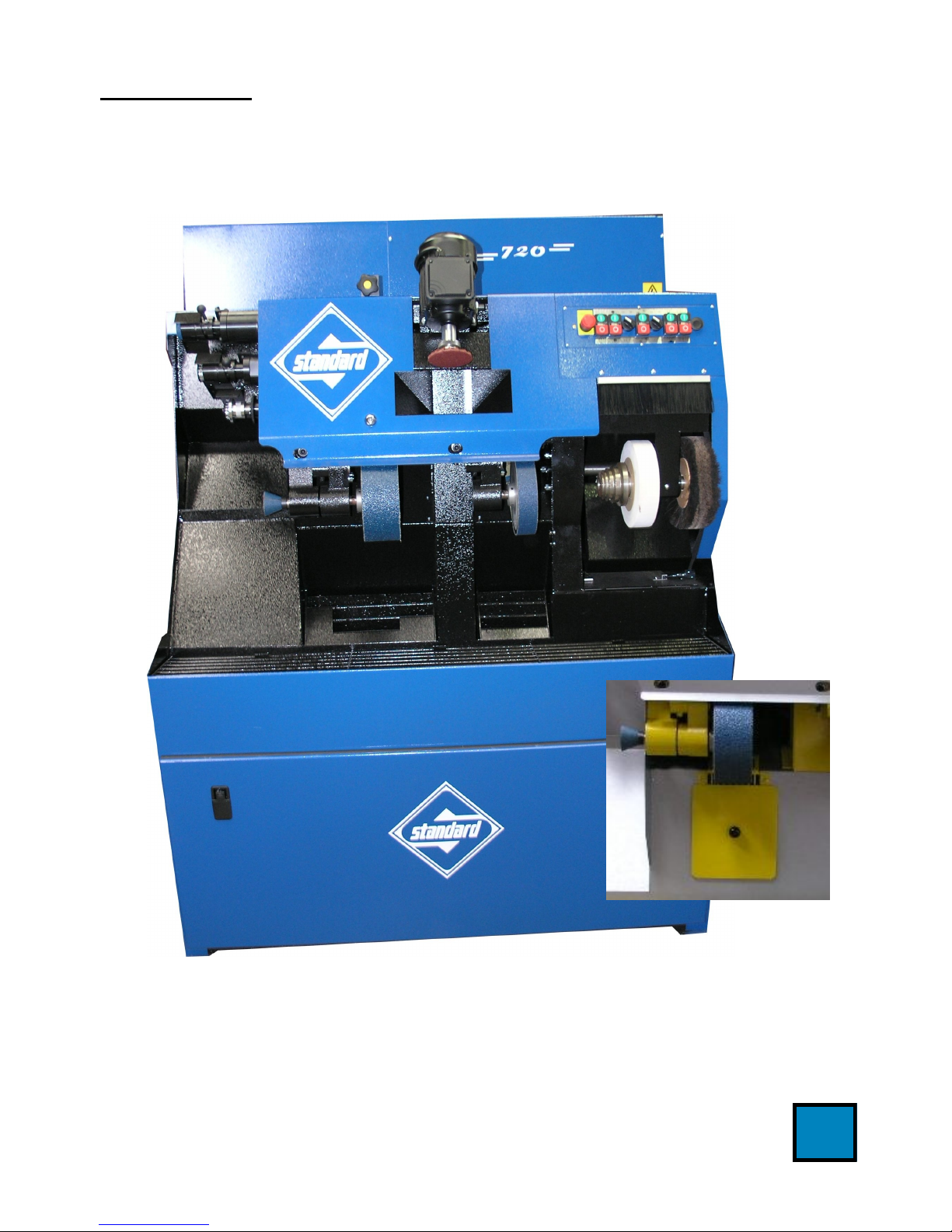
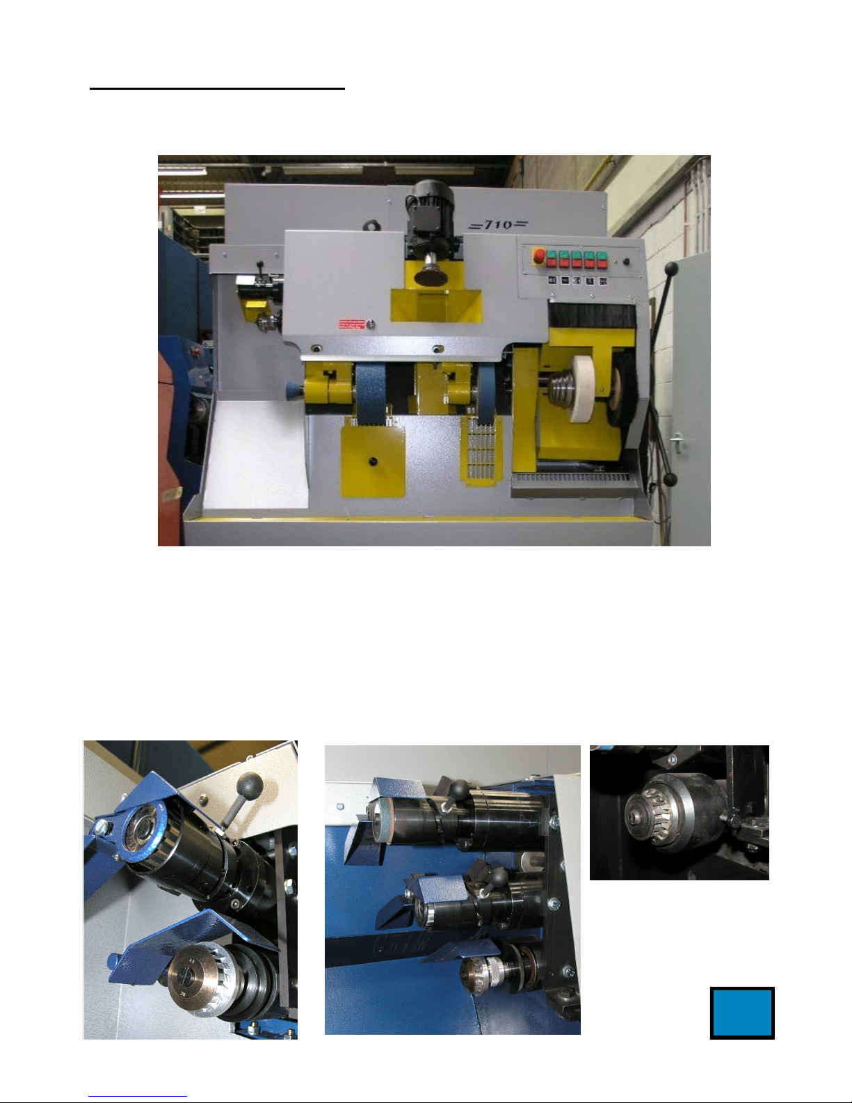
Machine Model 700 / 710 / 720 / 730 Finishing Machine
Markings - continued
Marking for the bag shaker activator: -
“Bag shaker operating knob.”
Electrical safety marking under front flap: -
“Tested for electrical safety”
Mass of machine - 390kilos
Dimensions: -
700 / 710 / 720 Finishers
1232mm W (plus additional 150mm for manual tumble on brush section)
x 780mm D x 1720mm H
730 Finisher
1232mm W (plus additional 150mm for manual tumble on brush section)
x 780mm D x 1480mm H
Handling Push back the front of the machine at a point above the centre of gravity
(approx. 900mm high and 600mm in from the left of the machine) to lift the
front base, and insert a lifting device under one end of the machine.
Use lifting device to raise one end of the machine and insert roller.
For short distance movement push at end of machine on roller (s). For
longer distance movement insert wheeled trolley or set of corner wheels,
and remove roller (s)
When in position required, reverse the above procedure.
Commission The machine shall stand firm and level. Use suitable packing material as
necessary to level, balance and secure the machine.
Position machine at least 100mm - 150mm from a rear wall to enable the
filter bag to remain clear of the wall when inflated.
The machine shall be connected by a competent person to the electrical
power supply and earthed through a suitable, lockable isolator conforming to
IEC 204/EN 60204. The electrical data are given on a plate attached to the
machine, and are as follows: -
5