Starizona Hyperion User manual
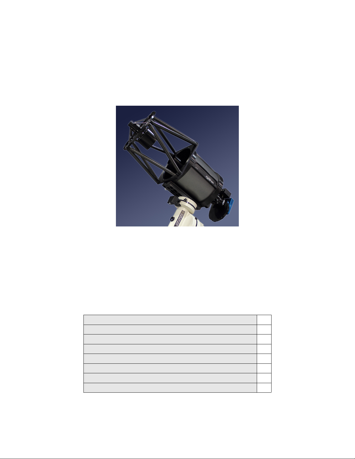
Hyperion
12.5” f/8 Astrograph
Operating Instructions
Thank you for purchasing a Hyperion telescope. You now own the most state-of-the-art
astrograph available. In addition to providing a large aberration-free flat field, the
Hyperion comes standard with a wealth of features.
This instruction manual will describe in detail the proper use of the Hyperion and its
many features. Please note the Warnings given in the ne t section in order to avoid
damaging your Hyperion.
Table of Contents
Warnings 2
Overview 5
Collimation 10
Telescope Control Panel 13
Telescope Control Software 17
Cleaning the Optics 24
ppendix 27
Specifications 30

Contact Information 30
Warnings
Things Not to Touch
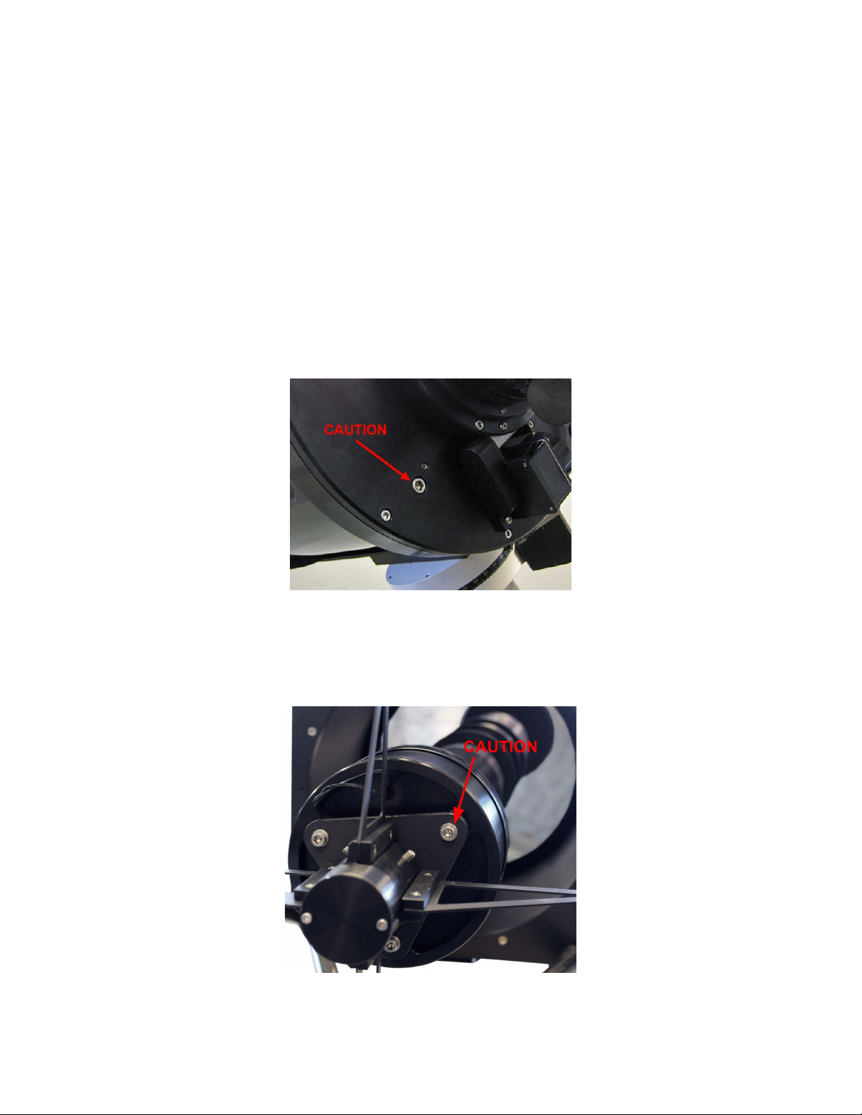
There are two adjustments made when the telescope is assembled and tested that should
not be adjusted by the user. First is the secondary mirror spacing. This is adjusted by a
nut located under the cover plate on the spider hub.
Don’t go there
Second is the corrector lens tip/tilt adjustment. This is located about halfway down the
outside of the primary baffle tube.
Don’t go there
Caution
Colli ation Bolts
The primary mirror assembly (including the mirror cell, mirror, baffle tube, and corrector
lenses) is held in place by the primary mirror collimation screws on the telescope back
plate. Do not loosen these screws too much or the whole assembly will fall off (this is a
bad thing), or more likely one screw will pop loose and you will have to take off the back
plate to reattach it. When collimating the telescope, make only small adjustments as the
telescope was collimated before shipping and should require only a little tweaking.
Same goes for the secondary assembly. It is held in place by its collimation screws.
Again, don’t loosen these too much or the assembly can become detached (another bad
thing). Make only small adjustments to the collimation screws. More details are in the
section on collimation.
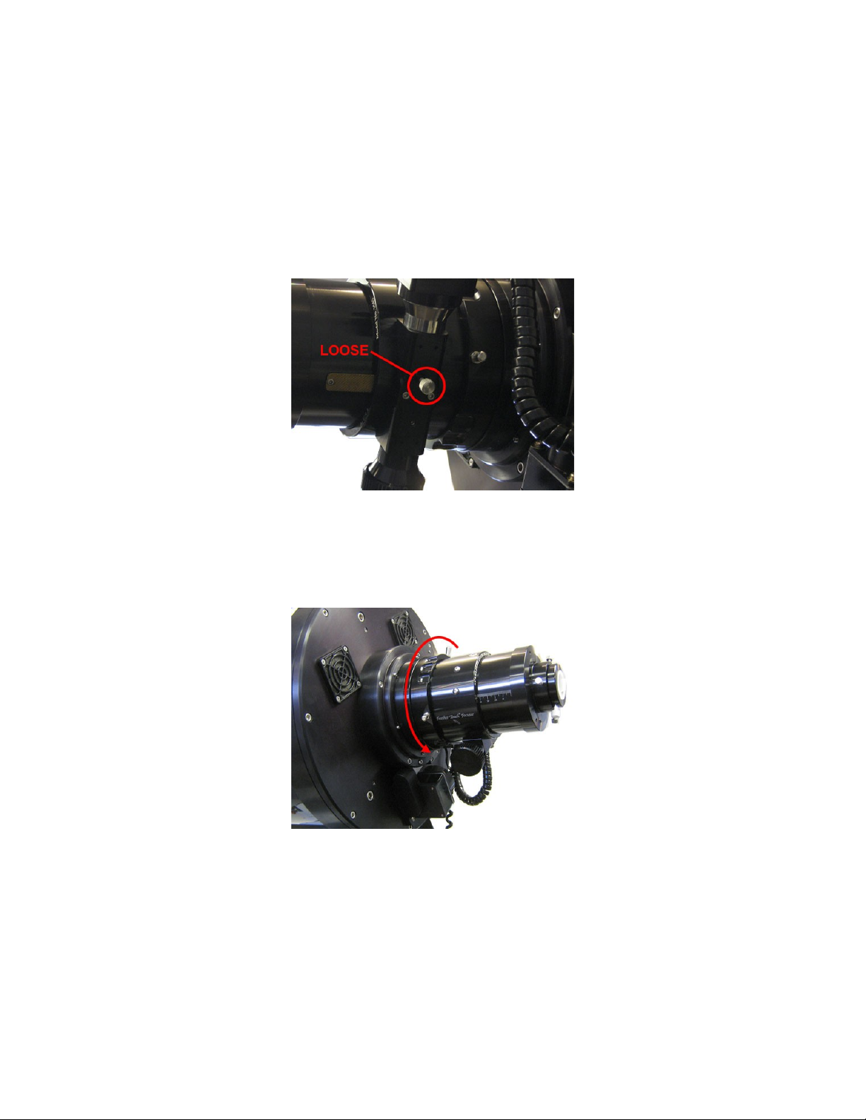
Focuser and Instru ent Rotator
The focuser and instrument rotator are designed to be moved electronically with their
motors. Do not attempt to move these units by hand. If for some reason is it necessary to
move the focuser drawtube manually, you may remove the motor and turn the focus knob
by hand. Note that there is a tension knob on the bottom of the focuser. When the
focuser motor is attached and in use, the tension knob should be loose.
The instrument rotator should never be moved by hand. Manual rotation of the focuser
can be achieved by loosening the lock collar on the Feathertouch focuser. Note that the
inde ing of the rotator is independent of the position of the focuser, so adjusting the
focuser’s rotation from its initial position is not necessary.
Telescope Overview
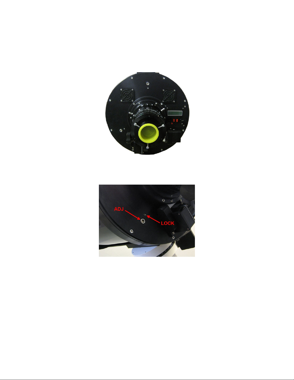
Back Plate Features
Located on the Hyperion’s back plate are the primary mirror collimation screws,
Telescope Control Panel, instrument rotator, focuser, and cooling fans.
There are si collimation screws—three adjustment and three lock screws. Recall that
the large screws are the only thing holding the primary mirror assembly. Use caution
when adjusting these screws. The screws are described in more detail in the section on
collimation.
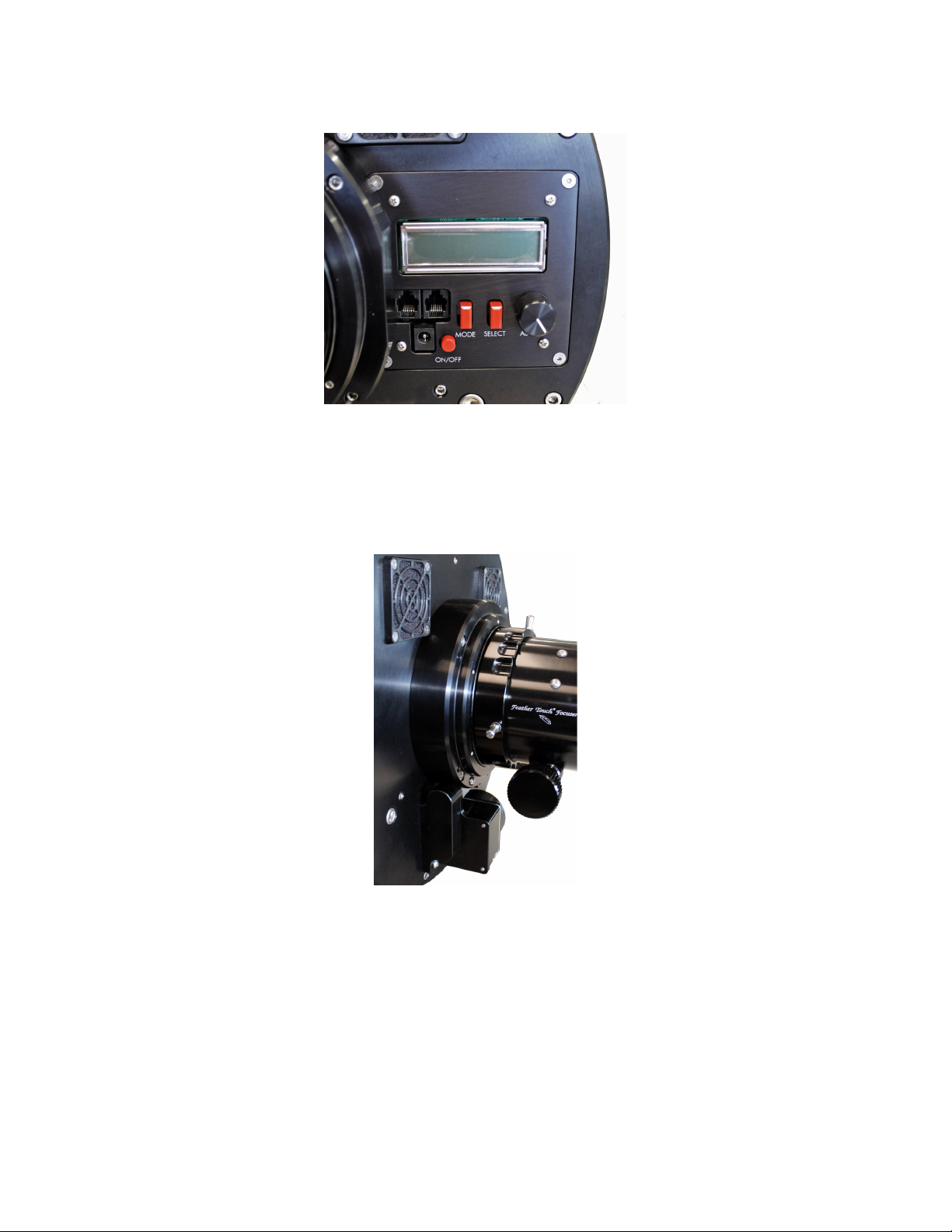
The Telescope Control Panel is the brains of the operation. This panel features an LCD
display and controls the instrument rotator, main Hyperion focuser, an optional
piggyback instrument focuser, cooling fans, and dew heaters. These features can also be
controlled remotely from a computer using the Telescope Control Software. More details
are in the section on the Telescope Control Panel and Telescope Control Software.
The high-precision instrument rotator allows accurate positioning of the camera for
framing a target or finding a guidestar. It can be controlled through either the Telescope
Control Panel or the Telescope Control Software.
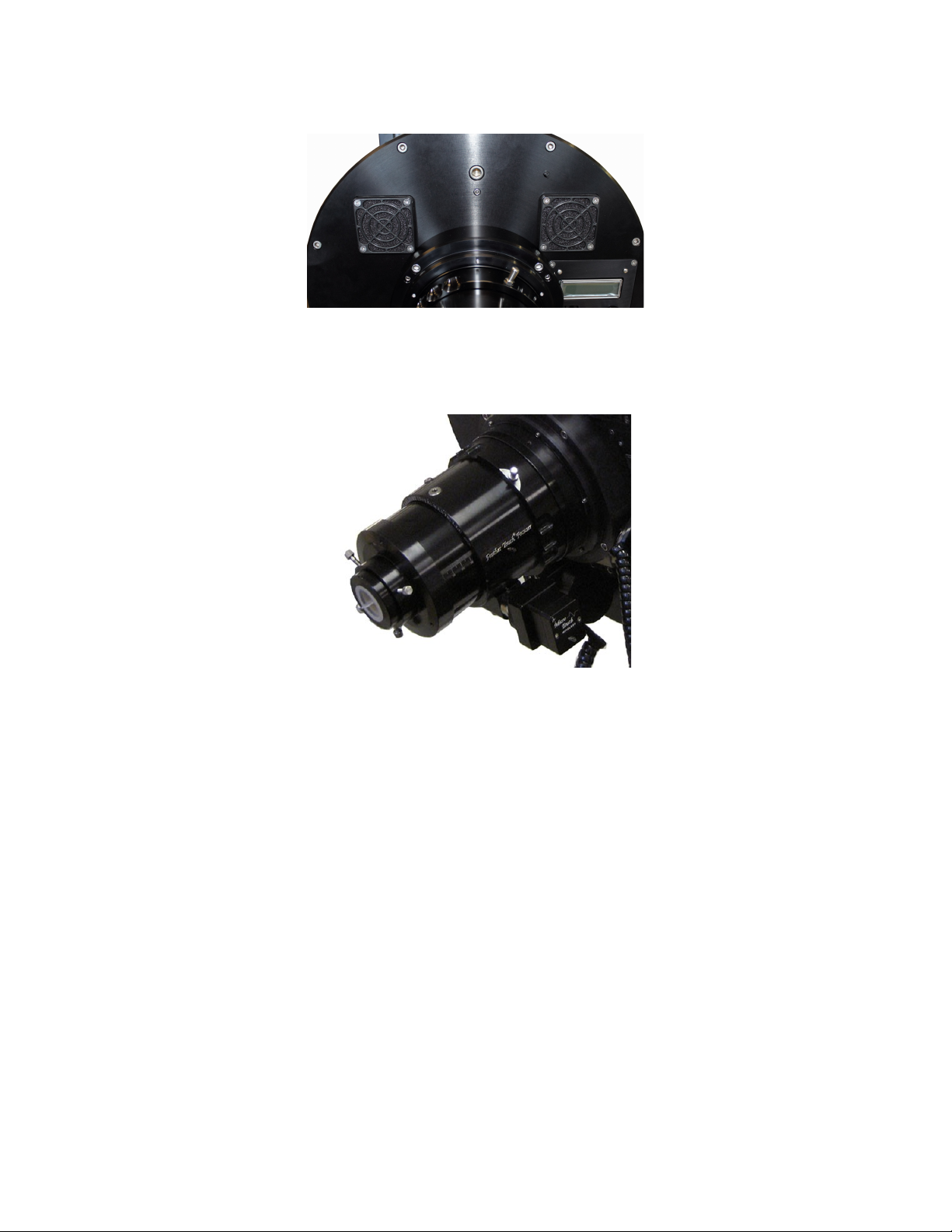
Dual cooling fans move filtered air around the primary mirror and through the optical
tube to accelerate thermal stabilization of the optics. This reduces the effect of tube
currents which can degrade seeing conditions.
The Hyperion uses a 3.5” Feathertouch Focuser for precise focusing. The focuser is
automated using Starizona’s MicroTouch autofocuser. The Feathertouch has 4.5”
(115mm) of focus travel and tick marks on the side of the focuser drawtube indicate the
current travel of the focuser in mm. The Hyperion has 7.33” (186mm) of backfocus from
the racked-in focuser drawtube to the focal plane. This distance does not include the
thickness of the focuser adapter, which varies by camera, but is appro imately 1”
(25mm) thick.

Other Features
The Hyperion features top and bottom Losmandy-style dovetail plates. The top dovetail
is ideal for piggybacking an optional guidescope or other wide-field instrument. The
dovetail will accept standard Losmandy accessories such as mounting rings and allows
you to balance the telescope by sliding the piggybacked instrument front to back. When
adding a second instrument, consider not only the weight of the instrument but also the
leverage due to the distance from the mount. This may make some instruments
impractical for some mounts. The distance between dovetails is 16” (406mm) and each
dovetail is 19.75” (502mm) long.
The secondary mirror is collimated with three screws attached to the triangular plate on
the spider assembly. A reminder that these three screws are the only thing holding the
secondary mirror assembly in place. Use caution when adjusting these screws. These
screws are described in more detail in the section on collimation.
The Hyperion has both primary and secondary mirror dew heaters to prevent moisture
from building up. The heaters can be controlled through either the Telescope Control
Panel or the Telescope Control Software.

Unique to the Hyperion is the ability to control all electronic features wirelessly. This is
done through the wireless control bo . The control bo plugs into your computer via a
USB cable and talks wirelessly to the Hyperion up to 300 feet away.

Colli ation
While the Hyperion was collimated and tested before being shipped, it likely will need
some slight adjustment after arrival. This section describes the full procedure for
properly collimating the Hyperion. The adjustments should be made in the order outlined
below.
Secondary Mirror Tilt
This is best evaluated using an optional laser collimator. Use the included 2” end cap for
the Feathertouch focuser to attach the laser collimator.
With the laser in place, look in the front of the scope. Look for the reflection of the
secondary mirror in the primary mirror. You should see the laser being emitted from the
bottom of the laser collimator. You should also see that the beam bounces off the
secondary and returns right on itself. If you see two red spots on the collimator, the beam
is not returning e actly onto itself and you need to adjust the secondary mirror.
This adjustment is done using the secondary collimation bolts. In order to adjust the
secondary mirror tilt, begin by loosening one of the collimation bolts (say, ¼ turn), then
tighten one or both of the other bolts. Remember that the bolts are the only thing holding
the secondary mirror assembly, so do not loosen them too much. Once the laser beam is
returning e actly on itself, the secondary mirror is appro imately collimated.

Star Test
To precisely collimate the Hyperion, a star test is required. Before beginning the star test,
allow the telescope to thermally stabilize for at least 30 minutes, preferably with the
cooling fans running. This eliminates any thermal distortion of the star image, which can
take on the same appearance as collimation error.
The star test is best done with a camera, while looking at the images on the computer
screen to evaluate the collimation. Aim the telescope to a moderately bright star. It is
important that the star is well centered in the field. Begin the star test by defocusing the
telescope. You will see a donut-shaped star image. If the telescope is out of collimation,
you will see the central obstruction is not concentric with the outer edge of the star image
(the donut hole will appear offset).
If adjustment is necessary, begin by loosening one of the collimation screws. Begin by
trying a small turn of the screw, say 1/8 turn, and begin by tightening the screw to bring
the mirror back. If this adjustment is the wrong way, return the adjustment screw to its
initial position and try one of the other screws.
Once the out-of-focus star image is concentric, the secondary mirror is collimated.
Adjustment of the primary mirror is done using the si screws on the back plate of the
telescope. The three smaller screws are lock screws, holding the mirror in place. The
three larger screws are the adjustment screws. These screws have springs on the them
inside the telescope, pushing on the primary mirror cell. Tightening them pulls the mirror
back; loosening them pushes the mirror forward.
Remember that the large screws are the only thing holding the primary mirror assembly
in place, so do not loosen them too much. Very little adjustment should be required.
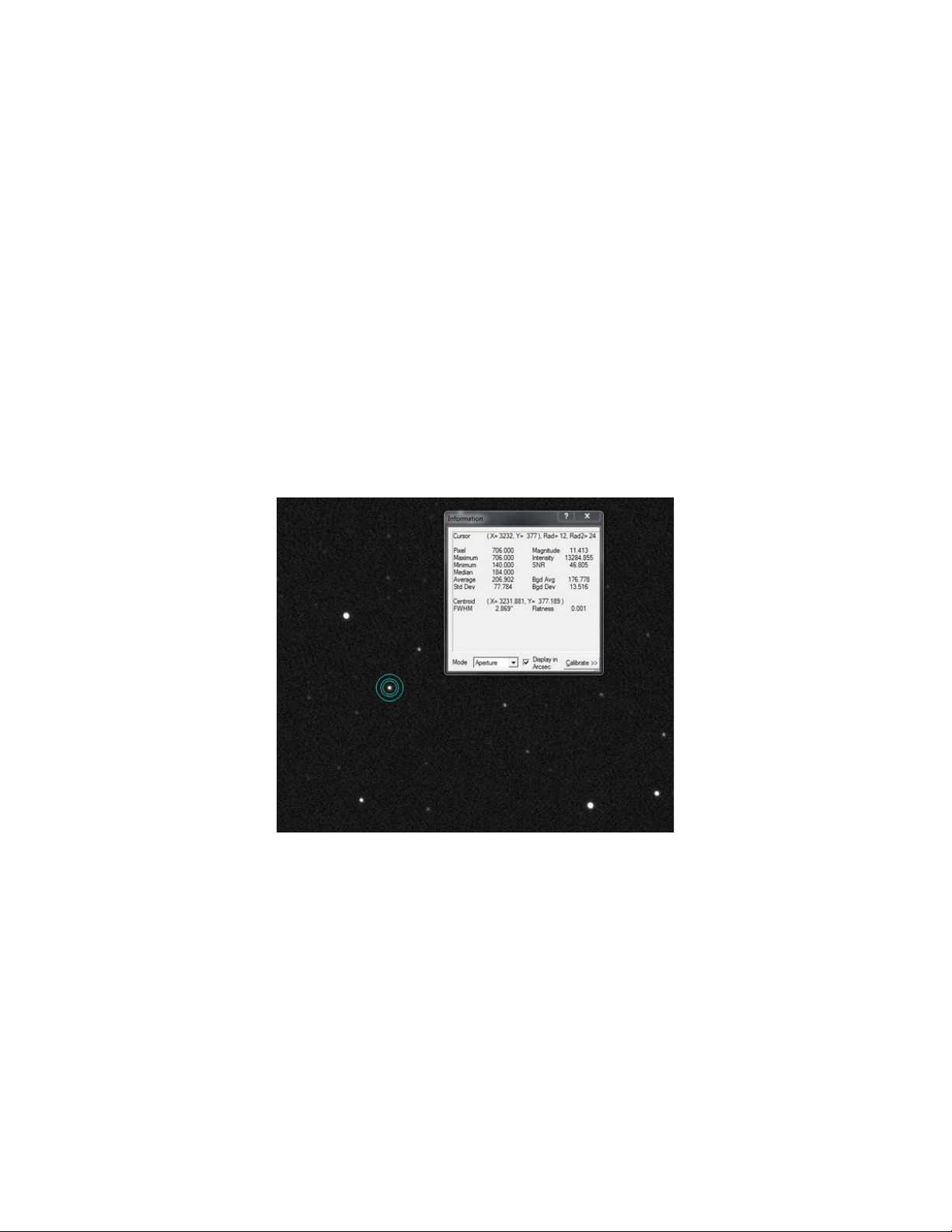
Bring the telescope to focus. Take a single frame e posure, about 5-10 seconds long, at
1 1 binning (full resolution). E amine the corners of the image at 100% magnification.
The stars should appear equally round in each corner. If using a program such as Ma Im
DL, you can make use of inspection tools to measure the average size of the stars in each
corner of the image.
If the star sizes are not equal, fine tuning is possible by making very small adjustments to
the primary mirror.
Begin by loosening one of the (small) collimation lock screws about 1/8 turn. Then
tighten the (large) adjustment screw.
Take another e posure. If needed, refocus the telescope. If things have improved,
continue until the stars are sharp across the full field. If things got worse, return the
adjusted pair of screws to their original position and select a different set of screws. Your
Hyperion is now perfectly collimated and ready for imaging!
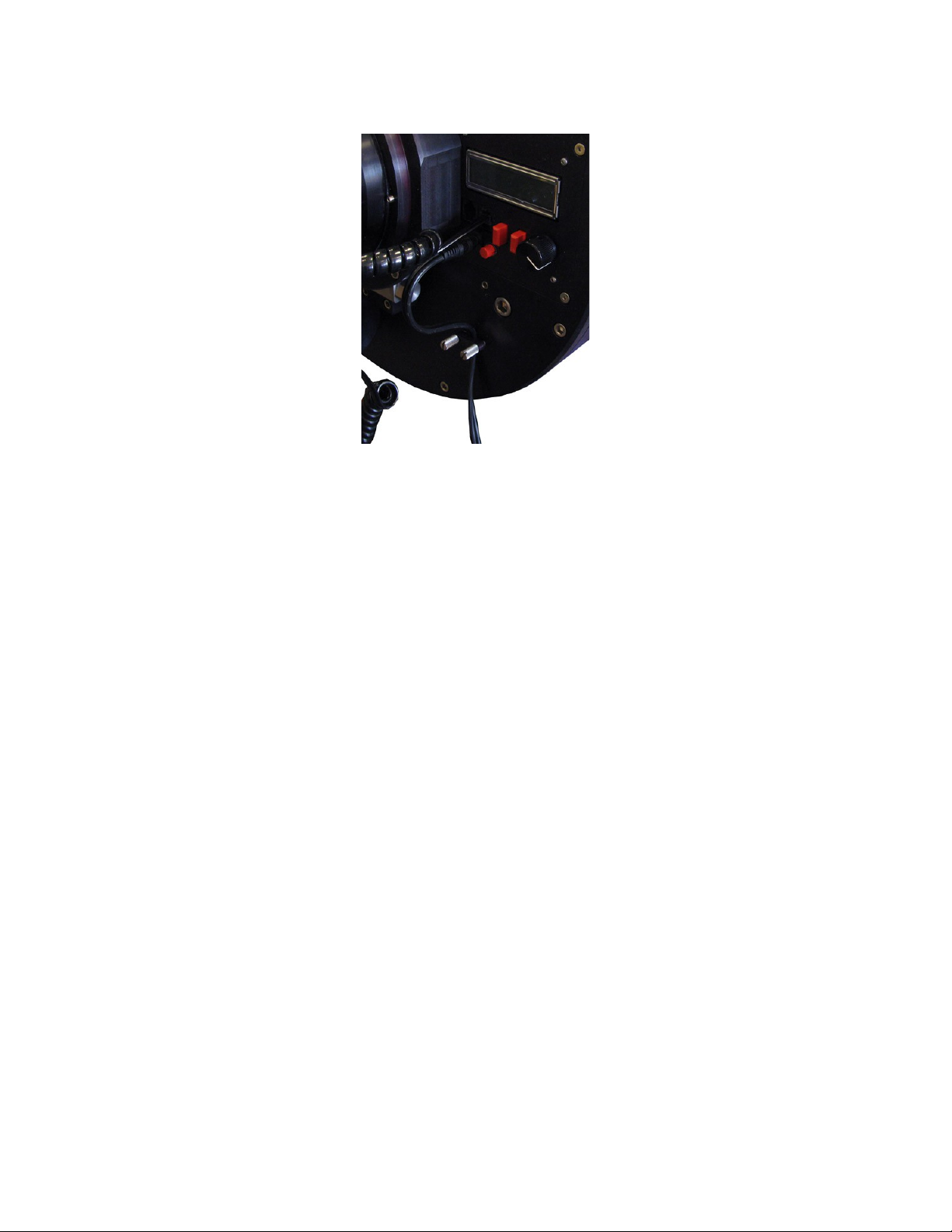
Telescope Control Panel
The integrated Telescope Control Panel operates all the electronic features of the
Hyperion. The controls on the panel consist of a Power button, Mode button, Select
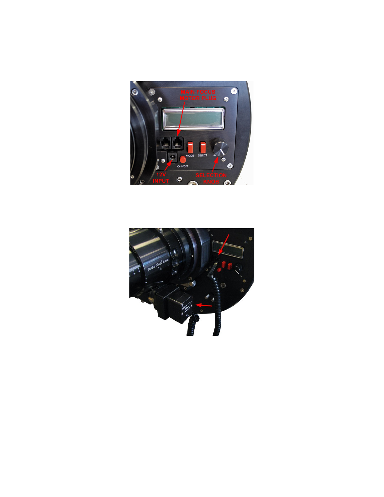
button, and Control dial. There are two focus motor plugs and one 12v power plug.
Start by connecting the included focus motor cable. The main focuser plug is the one on
the right. Connect this to the MicroTouch motor on the Feathertouch focuser.
To operate the control panel, begin by plugging in the 12v power supply. You can lock
down the cable with the clamp below the panel.
Press the Power button to turn the panel on. The cooling fans will run for a couple
seconds when power is first applied.
The default display on the LCD screen is for control of the main focuser motor. Turning
the Control dial will rack the focuser in or out. The screen displays both the requested
focus position and the current position. Turning the dial clockwise moves the focus
drawtube out, with the focuser position count increasing. Turning the dial counter-
clockwise decreases the position count and moves the focuser in. See the section below
on Setup for instructions on resetting the focuser position and reversing the direction of
travel.
Pressing the Mode button will scroll the menu on the LCD screen through the various
electronic features.
Guider
First is the Guider focuser, for an optional MicroTouch focuser on an optional piggyback
instrument.
Rotator
Ne t is the rotator control. The rotator can be inde ed in any position—see the section
below on Setup. Turning the Control dial clockwise turns the rotator clockwise. Position
angle of the rotator increases clockwise.

Fans
The ne t menu is for the cooling fans. Fan power is controlled by turning the Control
dial clockwise. Fan power is indicated in percent.
Heaters
Ne t is control of the primary mirror heater (Heater 1). Heater power goes from 0 to 100.
Secondary mirror heater (Heater 2) is controlled in the same way by the ne t menu.
Te perature
The following menu indicates ambient temperature. The default display is in degree F,
but it can be changed to degrees C by pressing the Select button. Rotate the Control dial
to view primary mirror temperature and secondary mirror temperature.
Telescope Control Panel Setup
The last menu on the panel is Setup. Press the Select button to enter the Setup menu.
The Mode button will scroll through the various devices. Pressing the Select button
enters that device’s setup menu.
Focuser Setup
Select Focuser in the Setup menu and press the Select button. The menu will display
Reset to 30000? Press and hold the Select button for 3 seconds to reset the focuser to
30000 counts, the middle of the default range.
Pressing the Mode button moves the menu to the ne t setting, Min Val: 0. Zero is the
default minimum value for the focuser. This can be increased using the Control dial.
Mode again will choose Max Val: 60000, which is the default ma imum focuser count.
This can be decreased using the Control dial.
Pressing Mode again will bring up Motor Rev: OFF. Press the Select button to turn on
the Motor Rev. This reverses the direction of the focus motor.
Ne t is Steps/Tick: 1. This can be increased up to 10 steps per tick. The number of
steps determines how far the focus motor will move per tick of the focus count. In other
words, the default setting of 1 pulses the motor once for every position count—increasing
the count by 1000 moves the motor 1000 steps. At 10 steps per tick, increasing the count
by 1000 moves the motor 10000 steps.

Lastly is Temp Comp: mbient. You can set the focuser’s temperature compensation
mode to use either ambient, primary mirror, or secondary mirror temperature for
reference.
Guider Setup
This works e actly the same as the Focuser Setup above, but controls the optional second
MicroTouch focuser on a piggybacked instrument.
Rotator Setup
The first selection is Reset to 0.0? Press and hold the Select button for 3 seconds to reset
the rotator position angle to 0.0. This initializes the position of the rotator. Normally this
would be set with the camera oriented orthogonal to the north-south line in the sky and
with the guide CCD above (north of) the main CCD.
Ne t is Motor Rev: ON. This is the default and turns the rotator clockwise when the
Control dial is turned clockwise and when the position angle increases. Press the Select
button to turn the motor reverse off.
Finally there is Wrap: 0. This sets the wrap limit on the rotator. It is set in number of
degrees that the rotator will turn past 180 degrees. You can dial in any number up to 360.
The default is zero, meaning the rotator will never turn more than 180 degrees before
taking the other direction to a given angle. This prevents cord wrap issues with the focus
motor and camera cables.
Te perature Co pensation Setup
The first setting in the Temp Comp menu allows you to turn on temperature
compensation and to select which device to use. Pressing the Select button turns the
temperature compensation on or off. Turning the Control dial selects the main focuser,
guider focuser, or both.
Pressing Mode switches to Learning mode. Turning this on begins the procedure for the
focuser to learn the temperature compensation characteristics of the Hyperion. Again,
each device can be selected with the Control dial.
Finally, there is Setup: Offsets. Here you can select ambient, primary, and secondary
temperatures and input offsets from the measured temperature to the actual temperature
for more precision. For e ample, if the ambient temperature is reading 75 degrees on the
control panel, and you know the actual temperature is 72 degrees, you can dial in a -3.0
degree offset in this menu.

Telescope Control Software
The Hyperion control software lets you operate all the telescope’s electronic features
remotely.
Power up the Hyperion telescope control panel and start the Hyperion software. Make
sure the USB wireless bo is plugged into the computer and press Connect.
The default window is for Main Focuser control. Once connected, you should see the
current focuser position displayed. You can manually change the focuser position by
clicking and holding on either the up or down arrows to the right of the position display.
To send the focuser to a given position, type the desired position into the Target Position
bo and press Goto. Note that the focuser has a range of 0-60000 counts.
To inde the focuser to a given position, enter that number in the Target Position bo and
press Reset to Target Position. This will set the current position to the targeted number.
Under Favorite Locations you can define up to three preset focus positions.
The Guide Scope Focuser window works identically to the Main Focuser window but
controls an optional piggyback instrument.
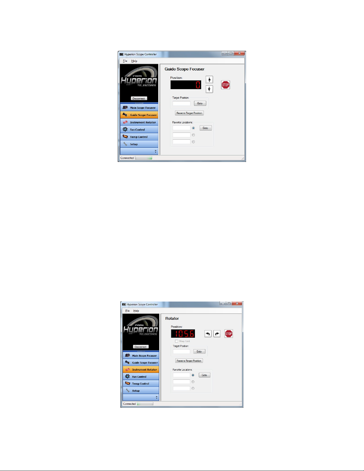
The Instrument Rotator window allows you to control the position of the Hyperion’s
instrument rotator. The current position is shown in the Position display.
By pressing the left or right arrows, you can manually move the rotator to any angle.
To send the rotator to a given position, type the desired angle (0-359) into the Target
Position bo and press Goto.
To inde the rotator to a given position, enter that number in the Target Position bo and
press Reset to Target Position. This will set the current position to the targeted angle.
Checking the Wrap Limit bo will enable the wrap limit set in the Setup window (see
below).
As with the focuser, you can preset up to three Favorite Locations.
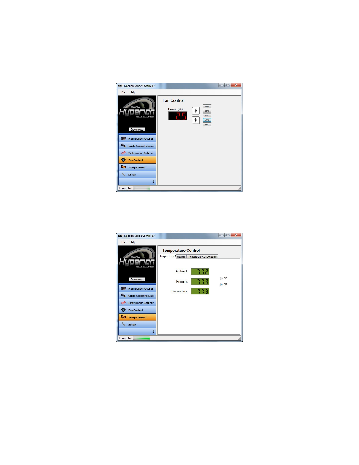
The Fan Control window displays the current fan power level. Pressing the up or down
arrows will manually increase or decrease the fan speed in 1% increments. You can also
select a predefined power level using the % buttons to the right of the arrows.
The Temperature Control window has three tabs. The first, Temperatures, shows the
current ambient temperature as well as the current temperatures of the primary and
secondary mirrors. The mode can be changed from degrees F to degrees C.
The Heaters tab allows you to manually set the power for each heater. Heater 1 controls
the primary mirror heater. Heater 2 controls the secondary mirror heater. The up and
down arrows will increase or decrease the heater power in 1% increments. Preset heater
powers can be set using the % buttons to the right of the arrows.

The Temperature Compensation tab allows you to control the temperature compensation
parameters. There are two ways to set the temperature compensation.
You can click on the Snapshot button to capture the current temperature data. Then, at a
later point in the night, click on the Comp. Immediate button. This will calculate the
temperature differential between the current conditions and those when you clicked the
Snapshot button earlier. The temperature compensation will be based on this differential.
Alternatively, you can let the Hyperion learn the correct temperature compensation
characteristics. Check the Learn bo . The current temperature information is recorded.
At a later time, uncheck the Learn bo and the differential will be calculated.
Check the Enabled bo to activate temperature compensation.
Table of contents
Popular Telescope manuals by other brands

Celestron LABS
Celestron LABS C90 MAK instruction manual

Celestron
Celestron 80AZS Quick setup guide

TwinStar Telescopes
TwinStar Telescopes 80mm Reflector Telescope Assembly guide

ORION TELESCOPES & BINOCULARS
ORION TELESCOPES & BINOCULARS SkyView Pro 100 EQ 9864 instruction manual

TMB Optical
TMB Optical TMB Optical TMB-80CF instruction manual

Celestron
Celestron TRAVEL SCOPE 60 instruction manual


