NPZ TAL -2 User manual

TELESCOPE ТАЛ -2 (ТАЛ-2Т)
SERVICE MANUAL

2
CONTENTS
Page
. General directions 3
2. Specifications 4
3. Standard equipment 5
4. Design and principle of operation of telescope 6
5. Preparation for operation 5
5.. Telescope assembling 5
5.2. Telescope balancing 6
5.3. Precautionary measures 6
6. Order of operation 9
6.. Operation with telescope 9
6.2. Photographic observations 2
6.3. Telescope and atmospheric conditions 22
7. Maintenance 23
8. Possible derangements and methods of their elimination 24
9. Rules of storage 26
0. Acceptance certificate 26
Supplement. Table of close stellar pairs for testing
image quality of the telescope 27
The telescope is subject to continuous development and improvement,
consequently it may incorporate minor changes in detail from the
information contained herein.
0.03

3
1. GENERAL DIRECTIONS
ATTENTION!
The telescope forms the inverted image like any
astronomical instrument does.
The direct observations of the Sun through the
black light filter are permitted only with the use of
a solar diaphragm.
Telescope ТАЛ-2 (ТАЛ-2Т) (hereinafter in the text referred to as
"telescope") is designed for visual observation of the celestial objects.
The telescope can operate normally at the ambient temperature from
30°C to minus 30°C.
When buying the telescope one should pay attention to the
package safety ensured by the seal of the manufacturing plant.
After unsealing the case one should check compliance of the complete
set denoted in the list of enclosure. Prior to using the telescope
one gets acquainted with its handling and order of operation.

4
2. SPECIFICATIONS
Diameter of primary mirror 50mm
Focal ratio f/8
Focal length 200mm
Magnifications:
-with the eyepiece of f'=40 mm 30x
-with the eyepiece of f'=25 mm 47x
-with the eyepiece of f'=7.5 mm 60x
-with the eyepiece of f'=40 mm and Barlow lens 95x
-with the use eyepiece of f'=25 mm and Barlow lens 58x
-with the eyepiece of f'=7.5 mm and Barlow lens 37x
Angular field of view of the telescope at magnification:
30x °2'
47x °
60x 0°29'
95x 0°29'
58x 0°7'
37x 0°8'
Resolution "
Limiting magnitude 2m
Range of slow-motion control on the declination axes ±4°
Rotation of the telescope:
in right ascension 360°(24h)
in declination 360°
Polar axis altitude adjustment 0° to 70°
Minimum distance of observation, mm 440
Voltage of the supplying mains 220/0±0°
Current frequency 50Hz (60Hz)
Output voltage of supply unit, V 2±0°
Angular field of view of the finderscope 7°
Magnification of the finderscope 8x
Sizes of the telescope:
length tube 200mm
height in the operating position 700mm
Weight of the telescope, maximum 40kg

5
3. STANDARD EQUIPMENT
Name Qty
Telescope
Supply unit
Eyepiece of f'=40 mm
Support 3*
Finderscope of 8x magnification
Pier *
Tripod *
Equatorial mounting
Bundled conductors
Bracket 2
Control panel **
Cable for car mains **
Accessories and Parts
Reticle
Barlow lens
Eyepiece of f'=25 mm
Eyepiece of f'=7.5 mm
Yellow light filter
Black light filter (solar)
Blue light filter
Red light filter
Green light filter
Neutral light filter (gray, lunar)
Blind
Fuse link ВПТ 9-0.6А (220V)
Fuse link ВПТ 9-0.32А (0V)
Cover
Adapter
Stopper
Cap

6
Name Qty
Screen (for observation of the Sun)
Market Containers
Housing
Housing
Service documents
Service manual
* Telescope can be completed with a metal pier (TAЛ-2) or
tripod (TAЛ-2T)
** Optional accessories
4. DESIGN AND PRINCIPLE
OF OPERATION OF TELESCOPE
The telescope consists of four basic units: the telescope tube, equatorial
mounting, pier with supports or tripod, supply unit.
The tube 5 (fig. ) is thebasic part of the telescope which embodies
the optical units: a primary mirror, a diagonal mirror, finderscope 3 fixed
in the locating rings 4, eyepieces and Barlow lens which are inserted in
focusing mechanism .
The primary mirror (fig. 3) is mounted in the cell and can be adjusted
by means of the screws and 2.
The diagonal mirror (fig. 4) is cemented to the cell and fixed in the
telescope tube by means of a spider. The inlet hole of the tube is covered
with cap 3 (fig. 9) after operation.
Finderscope 3 (fig. ) is a scope with 8x magnification and field of
view of 7°.
The focusing mechanism 1 (fig. ) is composed of a rack and pinion.
The pinion axle carries the handwheels which help to move the eyepiece

7
- focusing mechanism; 2 - bushing; 3 - finderscope; 4 - ring;
5 - telescope tube; 6 - equatorial mounting; 7 - pier;
8 - bundled conductors; 9 - supply unit; 0 - cord; - supports;
2 - control panel
Fig. . General view of telescope with metal pier:
1
2
3
4
6
5
11
8
7
9
10
12

8
Fig. 2. General view of telescope with tripod:
,2 - stops; 3 - objects table

9
tube. The smoothness of the tube movement can be controlled. For this
purpose the left handwheel is held by one hand and the right handwheel
is rotated clockwise (with some effort) relative to the left handwheel by
the other hand. The chosen position of the tube can be fixed in this way,
if necessary.
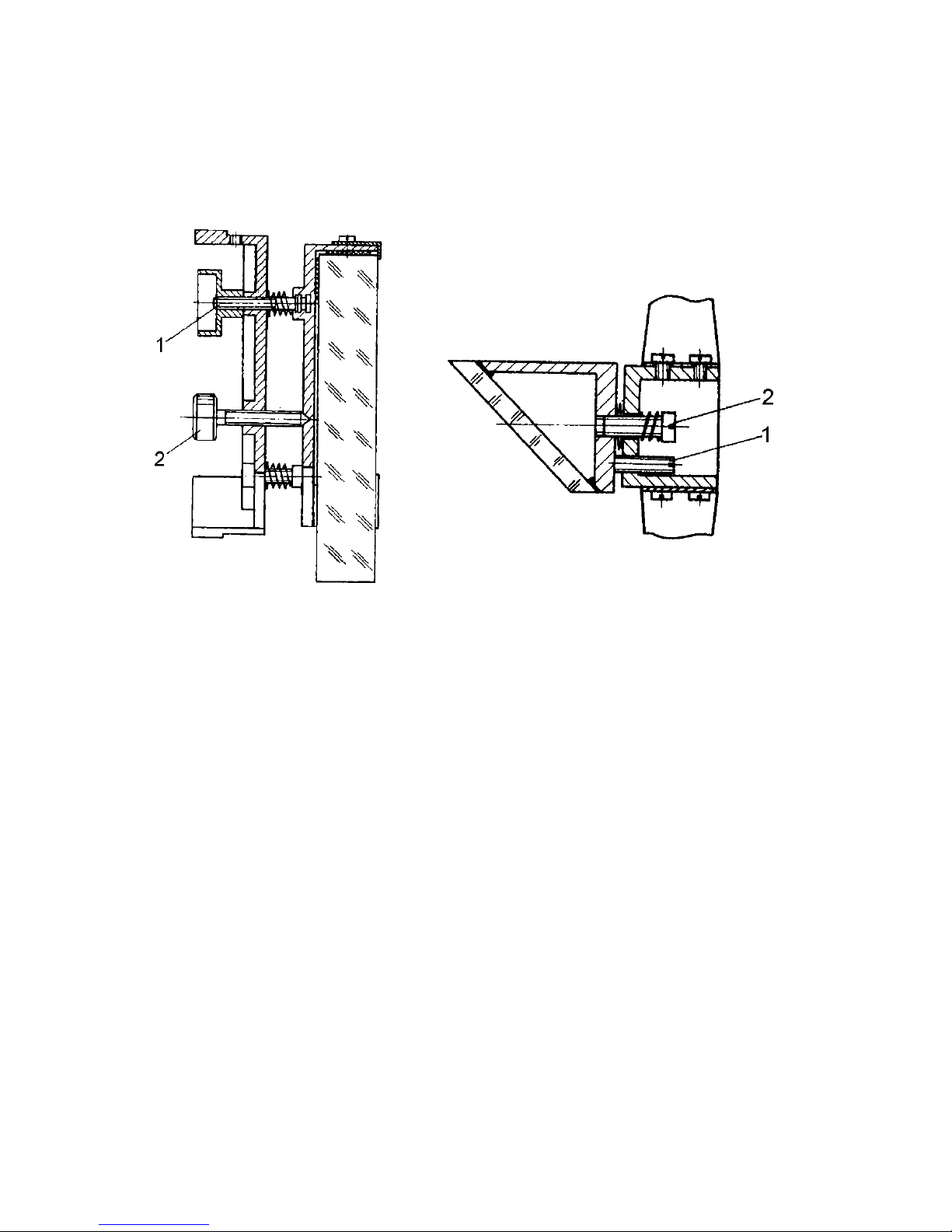
Fig. 3. Primary mirror: Fig. 4. Diagonal mirror:
- set screw; 2 - adjusting - adjusting screw; 2 - set
screw screw
The telescope is complete with six light filters 6 (fig. 9)
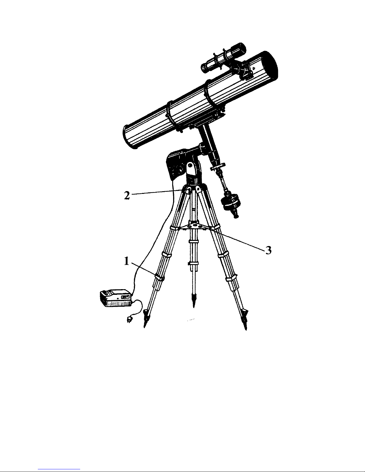
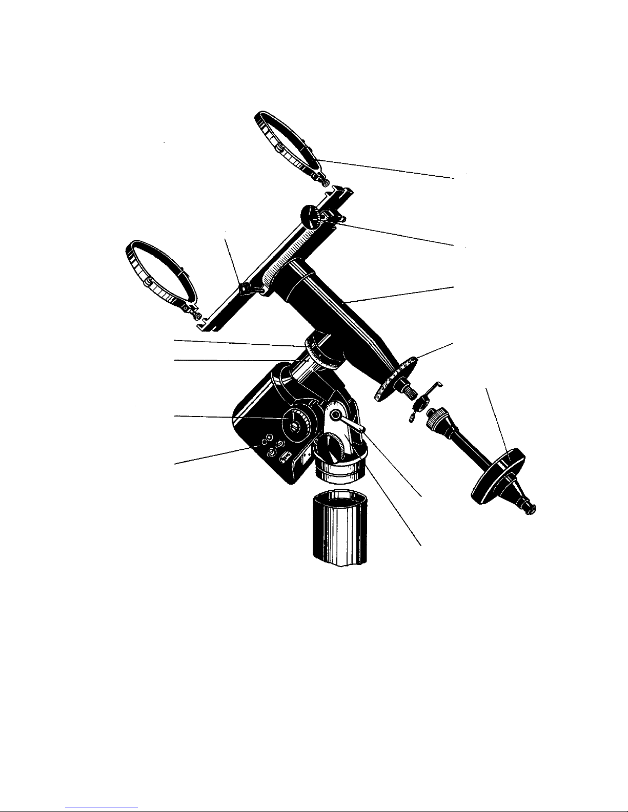
The equatorial mounting (fig. 5) consists of polar axes 0 and
declination axis 3 perpendicular to the polar axis.
Fastened on one end of the declination axis is the saddle with hinged
clips in which the telescope tube is mounted; fastened on the other
end of the axis is the counterweights 5 which can move along the
axis for balancing the telescope tube. Solar-screen (fig. 9) can be
fastened on the same axis as well.
The casing of the polar axis is fastened on the bracket 7 (fig. 5) provided
with a scale of latitudes by which the polar axis is set to the latitude
of the observer’s site.
The southern (lower) end of the polar axis embodies electric clock drive 8,
the northern (upper) end embodies the casing of declination axis 3.
Both axises are provided whith a setting circles which shows an
hour angle or declination of the object visible in the telescope field of
view. Setting circle 4 on the declination axis which shows the object

0
1
2
12
11
3
4
5
10
9
8
6
7
Fig. 5. Equatorial Mounting:
- folding clips; 2 - micrometer screw of slow-motion mechanism;
3 - declination axis; 4 - circle of declinations; 5 - counterweights;
6 - bolt; 7 - bracket with scale of latitudes; 8 - electric watch drive;
9 - handwheel of micrometer screw of polar axis;
0 - polar axis; - circle of hour angles; 2 - screw of axis brake

declination is figured from 0 to 90° with a division value of °. Circle
positioned on the polar axis (the circle of hour angles) is figured from
0 to 24 hours with a division value of 0 minutes.
The declination axis has braking screw 2 and mechanism 2 of
slow motion which moves the tube in the range of ±4°. By using this
mechanism it is possible to correct the position of the object in the field
of view. The equatorial mounting is connected to the pier.
Pier 7 (fig. ) consists of a pipe with three supports .
The tripod (fig. 2) allows to adjust a height of telescope and to fix each
leg of tripod with the help of stops and 2.
Supply unit 9 (fig. ) powers the watch drive tracking the celestial
objects. It is designed for 220 V/ 50 Hz (0V/60Hz) mains and activated
with the key. If the control panel is provided the car’s mains or storage
battery 2 V can be used through the car’s cable.
The control panel (fig.6) is designed to select modes of watch drive
by means of buttons 2. The watch drive provides the sun, celestial and
moon speed modes. The control panel is equipped with the local lighting
which can be switched on by button 4.
The reflecting telescope is the Newton optical system (fig. 7).The
parallel beam of rays enters the telescope tube, falls on the primary
mirror and, after reflecting from it deflect by diagonal mirror 3, at 90°
and is viewed with the help of the eyepiece 2.

2
Fig 6. Control Panel:
- indicator; 2 - speed selection buttons; 3 - correction buttons;
4 - lighting button; 5 - plug

3
Fig. 7. Optical train of telescope:
- primery mirror; 2 - eyepiece; 3 - diagonal mirror; 4 - finderscope

4
Fig. 8. Diagram of setting Barlow lens
Eyepiece
Barlow lens
Eyepiece
Focusing mount
Focusing mount

5
5. PREPARATION FOR OPERATION
5.1. Telescope assembling
Prior to assembling the units and parts should be cleaned from the
slushing compound of the plant.
The telescope is assembled in the following way.
Three supports provided with captive screws are fixed to the lower
end of the pier through holes. The equatorial mounting is set on the upper
end of the pier. At the same way it is fixed on the tripod.
In order to aim the polar axis turn the equatorial mounting by the value
of the observation site latitude by means of elevation gear and latitude
scale. Lock the direction adjusted with the lock handle.
Mount the axle with the counterweight 5 (fig. 4) on the declination
axis unit and fasten it with the nut. Mount the clips on the bracket and
then the telescope 5 in them (fig.).
The telescope tube is mounted on the supports of the saddle and fixed
by means of two clips with the help of hinged screws.
The finderscope is mounted on the tube in two rings and fixed with
six set screws available on the rings.
In transportation and storage a hole in the eyepiece tube is plugged
with a stopper which should be removed and put in the case in preparation
for operation.
For obtaining the required magnification of the telescope the
respective eyepiece or the eyepiece with Barlow lens 4 (fig. 9) is inserted
in the eyepiece tube.
A toggle switch of the supply unit is to be set in position "0".
Connect bundled conductors 8 (fig. ) to the clock drive and to the
supply unit through a socket designated, connect a plug of cord 0 of
the supply unit to the mains of 220/0V. Set the toggle switch of the
supply unit in position "I", set the toggle switch of the drive in position
"I". A light indicator on the clock drive must light.
The control panel if provided is connected to the mounting by means
of the plug 5 (fig. 6).
Set the switch of control panel operation on the mounting into “I”
position. The watch drive is activated by one of the buttons 3. When it

operates the indicator lights. The switch of autonomous operation on
the mounting and the key of supply unit must be set into “I” position
previously.
5.2. Telescope balancing
For smooth motion of the telescope and reliable operation of the
slow motion knob it is important to balance its movable parts on the
axes of the equatorial mounting.
For this purpose one should set the telescope tube in the horizontal
position, unscrew the bolt of brake 6 (fig. 5) of the declination axis and
holding slightly the tube by hand see to it whether it remains in the
indifferent equilibrium. If the tube is not in balance, undo the screws
of the clips which fix the tube and move the tube along its axis until it
will be in balance. After that one screw in the screws of the clips.
For balancing the telecope relative to the polar axis it is necessary
to set the declination axis in the horizontal position.Then it is necesary
to slacken each of three screws 2 through cap of the watch drive
(fig. 0). Holding the axis by hand see to it whether the telescope is in
balance about the polar axis. If the telescope is not in balance, move
counterweight 8(fig.5) along the declination axis. After balancing tighten
screws 2 of the friction clutch (fig. 0) on the polar axis so that the
telescope can not rotate easily.
The adjustment of the friction clutch is considered to be finished if the
telescope tube moves due to the minor effort of the hand.
When mounting the various devices on the telescope, for example,
a camera, it is required to balance the telescope additionally.
5.3. Precautionary measures
The rate of the fuse link mounted in the supply unit must be in
compliance with the rate denoted under the fuse link holder.
Mount the fuse link only after complete disconnection of the supply
unit from the mains.
Connect the bundled conductors to the watch drive and supply unit
when the supply unit is disconnected from the mains.
6

Fig. 9. Tools and accessories:
- solar screen; 2 - cap-diaphragm; 3 - cap; 4 - Barlow lens;
5 - eyepieces; 6 - light filters; 9 - blind; 0 - reticle; - adapter
7

8
Fig. 0. Watch drive:
- worm gear wheel; 2 - cap; 3 - screw; 4 - handwheel; 5 - screw;
6 - screw; 7 - motor; 8 - screw; 9 - worm with gear wheel;
0 - worm wheel; - cap; 2 - screw; 3 - cover
1
2
3
4
5
6
78
9
10
11
12
13

9
6. ORDER OF OPERATION
6.1. Operation with telescope
Before mounting the telescope it is required to choose a place and
prepare a site. It must be even and solid. Mount the telescope on the
site and check it for reliable stability.
For pointing to an object the telescope should be rotated about two
axes. For rotation of the declination axis it Is necessary to undo braking
screw 2 (fig. 5), rotate the telescope and screw in the bracking screw.
If backlash is arisen in the worm gear it is necessary to disengage motor
7 (fig. 0). For this purpose it is required to take off cap 3, slacken three
screws 8, displace motor 7 upwards and fix it with screws 8. Remove
handwheels 4 after unscrewing screws 5. After that slacken screws 6
which fasten worm 9 in the bearings. After pressing the worm to worm
wheel 0 fix it with screws 6. Mount handwheels 4 and secure them
with screws 5. Then slacken screws 8, displace the motor downwards
until engagement with the toothed wheel of the worm takes place and
secure them with screws 8. Mount cap 3 on the casing.
The smoothness of rotation of toothed wheel together with the toothed
wheel of worm 9 is checked by rotation of the handwheels, in doing so
probable sliding or jamming of the friction clutch may take place.
For its adjustment it is required to displace cap 2 and tighten or slacken
three screws 3. The friction clutch adjustment is considered to be finished
if handwheels 4 rotate smoothly.
The telescope rotates about the polar axis owing to minor effort
and is not fixed. The axis is connected to the watch drive with the help
of a friction mechanism.
The celestial sphere and all astronomical objects perform a complete
rotation for twenty four hours. As a result the object in the telescope field
of view displaces constantly. The speed of its displacement increases with
the increase of the telescope magnification. Therefore, the telescope is
provided with electric clock drive 8 (fig. 5) which rotates uniformly the
telescope which follows the object. As a result, in the process of obervation
the object remains constantly at the centre of the field of view.

20
In the process of observation it is often required to perform minor
corrections in the diurnal run of the telescope. For this purpose one
makes use of handwheels 4 (fig. 0) or the buttons 3 (fig. 5) of the control
panel. The buttons 3 speed up or slow down the tracking speed of the watch
drive relative to the nominal providing the correction of right ascension
angle. The correction modes are activated when one of the buttons 3 is
pressed continuously and the indicator blinks. If the button 3 is released
the tracking speed returns to the nominal.
The telescope has high magnifications and, hence, small fields of
view, therefore it is provided with a finderscope.
After mounting the telescope it is necessary to set parallel of the optical
axes of the telescope tube and finderscope. For this purpose one should
mount a reticle with cross into the eyepiece f'=25 mm. One should make
an adjustment by remoted object.
By operating with the set screws of rings 4 (fig. ) of the finderscope
one brings the chosen remote object to the centre of the finderscope
field of view. This operation is performed once. In the future before
observation only a check-up of parallelism of the telescope and
finderscope optical axes is needed.
In order to avoid corrections of the declination axis during operation
of the watch mechanism it is required to set the telescope polar axis
in parallel to the celestial axis. In this case the northern (upper) end
of the polar axis faces the celestial pole positioned near Polaris (a
Ursae Minoris). For visual observations it is enough to incline the poral
axis at an angle equal to the latitude of the observing site and direct it
approximately along the line the South - the North. With such coarse
setting of the telescope the object will “deviate” step by step in declination
(it is lifted or lowered in the field of view). This error is corrected at times
by means of the micrometer screw of the declination axis.
For photographic operations and in the case when the telescope can
be set stationary, the polar axis of the telescope should be set precisely.
For this purpose one observes any bright star in the East, then in the
South and makes notice of the direction of the star displacement.
If in observation of the star in the East it is displaced in the telescope
field of view so that in its tracking the upper end of the telescope tubes
sinks slowly, the north end of the polar axis should be somewhat
lifted.
If the upper end of the tube is lifted step by step, the north (upper) end
of the polar axis should be lowered.
For precise setting of the axiss by azimuth one observes the star
near the meridian circle (above the south point) in the same way.
If in the star tracking one has to lower slowly the upper end of the
This manual suits for next models
1
Table of contents
Other NPZ Telescope manuals
Popular Telescope manuals by other brands

Dorr
Dorr Danubia Atlas 2000 instruction manual

National Geographic
National Geographic NG70FS owner's manual

Celestron
Celestron PowerSeeker 70EQ quick start guide

Celestron
Celestron FirstScope 90EQ Quick setup guide

Burris
Burris BTH 25 user manual

William Optics
William Optics ZenithStar 80 instruction manual

Zhumell
Zhumell SPOTTING SCOPE owner's manual

Bresser
Bresser Space Explorer 90/900 EQ instruction manual

Vixen
Vixen BT81S-A instruction manual

Unistellar
Unistellar eVscope eQuinox user guide

Astronomers Without Borders
Astronomers Without Borders AWB 130 NEWTONIAN instruction manual

Zhumell
Zhumell ECLIPSE 114 user manual