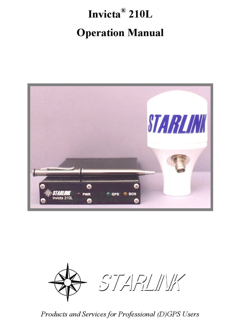
STARLINK INVICTA 210S User manual

INVICTA®210S
DGPS/BEACON RECEIVER
Operation Manual
Products and Services for Professional (D)GPS Users

Starlink Incorporated
500 Center Ridge Drive
Suite 600
Austin, TX. 78753
Voice: 1-512-454-5511
FAX: 1-512-454-5570
www.starlinkdgps.com
Copyrights
© 1999, 2000, 2001 Starlink Incorporated. All rights reserved. No part of this manual may be copied,
photocopied, reproduced, translated, or reduced to any electronic medium or machine-readable form
without prior written consent from Starlink Incorporated.
Printed in the United States of America.
Part No. 016-0171-095 Rev C

Starlink Incorporated
Invicta 210S Operation Manual page 3of 46
Table of Contents
Introduction....................................................................................................... 5
Functional Description ...................................................................................... 5
GPS Receiver ............................................................................................. 5
MSK Radiobeacon Receiver ...................................................................... 6
L-Band OmniStar™ Receiver.................................................................... 6
Front Panel Control.................................................................................... 7
MBA-4 Antenna......................................................................................... 7
Utility Software................................................................................................. 8
Receiver Firmware Updates.............................................................................. 8
Special Features ................................................................................................ 8
Installation....................................................................................................... 10
Initial Power up........................................................................................ 10
Power ....................................................................................................... 12
Receiver ................................................................................................... 12
MBA-4 Antenna....................................................................................... 12
Antenna Cable.......................................................................................... 13
Operation......................................................................................................... 14
Initial Startup ........................................................................................... 14
Activation of OmniStar™ Service ........................................................... 14
Normal Operation .................................................................................... 14
Front Panel Display......................................................................................... 15
Home Screen ................................................................................................... 18
Receiver Display ............................................................................................. 19
GPS Display.................................................................................................... 20
RTCM Display................................................................................................ 22
Beacon Display ............................................................................................... 23
OmniStar Display............................................................................................ 25
Utility Options................................................................................................. 27
Receiver Configuration Menu......................................................................... 29
GPS Configuration Menu................................................................................ 31
RTCM Config Menu ....................................................................................... 32
Beacon Config Menu ...................................................................................... 33
OmniStar Config Menu................................................................................... 34
Output Config Menu ....................................................................................... 36
Troubleshooting .............................................................................................. 38
Checking Your Installation ...................................................................... 38
Receiver Specifications ................................................................................... 39
Antenna .................................................................................................... 39

Starlink Incorporated
page 4of 46 Invicta 210S Operation Manual
Configuration .................................................................................................. 40
Rear Panel Serial Interface....................................................................... 40
Power Connector...................................................................................... 40
Global Positioning System (GPS) ................................................................... 41
Differential GPS (DGPS) Beacon ................................................................... 42
DGPS OmniStar. ............................................................................................. 43
NMEA Messages ............................................................................................ 44
Sample GGA Message Structure..................................................................... 45
Warranty.......................................................................................................... 46

Starlink Incorporated
Invicta 210S Operation Manual page 5of 46
Introduction
The Starlink Invicta® 210S GPS receiver will provide you with highly accurate and reliable
DGPS navigation. This receiver is ideal for GIS, professional marine, precision farming or any
other application where a high performance, rugged, and simple to operate receiver is required.
Functional Description
The Starlink Invicta®210S is a 10 channel high-performance GPS receiver with two built-in
DGPS correction receivers. You can select the built-in MSK Radiobeacon receiver, L-Band
OmniStar™ receiver, or an external RTCM source for your DGPS corrections. You can even let
the receiver automatically select its correction source by using the auto DGPS input mode.
DGPS corrections are needed to improve the accuracy of standard GPS. If you operate without
DGPS corrections, the accuracy will be about 10 meters RMS. This means the receiver can have
errors as far off as 33 feet in any direction 67% of the time, and greater 33% of the time. Prior to
the government turning off Selective Availability (SA), this error was 100 meters RMS. With
DGPS corrections, the receiver can give you positions with a RMS accuracy of 1-meter (an error
equal to about the length of your arm in any direction).
Reference stations measure GPS errors and broadcast correction messages. The Invicta receives
these DGPS corrections either from a free radiobeacon or via the OmniStar™ service and
produces accurate position reports.
Since the Invicta 210S has both a radiobeacon receiver and an L-Band OmniStar™ receiver, you
have a choice of either source for your DGPS corrections. If you can receive one of the free
radiobeacon stations then you can use it for your corrections. If you are not in range of a free
radiobeacon, you can receive corrections via an L-Band satellite service offered by OmniStar™.
The OmniStar™ service is not free but is available over land almost everywhere on the planet.
For the functional description we can break the Invicta 210S into several parts. Each is described
in the following sections.
GPS Receiver
The Invicta 210S GPS receiver provides real-time positions with a RMS accuracy of 1-meter.
The receiver can generate position solutions once per second or optionally at 10 solutions per
second. Position solutions are output on either the front panel or via RS232 in NMEA format
messages.
The Invicta 210S has two RS232 ports and can communicate at 1200, 2400, 4800, 9600, 19.2K,
or 38.4K BPS on either/both port(s). The baud rate and the desired output messages can be
configured either from the front panel or via the serial port using configuration messages.

Starlink Incorporated
page 6of 46 Invicta 210S Operation Manual
NMEA format messages are standard for most GPS receivers and therefore should be
compatible with almost any software or hardware application designed to work with GPS. A
document describing the NMEA messages supported by the Invicta is available on the Starlink
web site.
MSK Radiobeacon Receiver
Invicta receivers include a dual-channel beacon receiver with advanced impulse noise
processing. USCG, Canadian, or IALA (International Association of Lighthouse Authorities)
beacon stations can be used to provide free DGPS corrections for ranges of up to 300 miles.
Dual channels are used to provide reliable automatic station selection. The receiver can track
one beacon to get corrections and use the other channel to test for new or better stations. The
switch between an old and a new beacon occurs instantly with no loss of differential data.
The receiver actually has a third channel to detect impulse noise. Impulse noise is caused by
thunderstorms or by man made sources such as the ignition system on a car. The third channel
detects these pops and clicks in the signal and automatically removes them. Starlink has always
been the absolute leader in impulse noise processing which is the real performance-limiting
factor in beacon receiver design.
L-Band OmniStar™ Receiver
The Invicta 210S has a built in satellite differential correction receiver in addition to the dual
channel radiobeacon receiver. The L-Band receiver gets corrections from a satellite service
offered by OmniStar™. The OmniStar™ service is not free, but it is available over most of the
land on earth.
To receive the L-Band corrections you first must contact OmniStar™ to activate the service.
OmniStar™ contact information is included in the package with the receiver. You can check
service details via the OmniStar™ web site at http://www.omnistar.com.
The OmniStar™ signal offers some possible advantages over radiobeacon signals.
Radiobeacon signals are sometimes interfered with by thunderstorms or other sources of man
made noises commonly found around computer equipment. The OmniStar™ signal is very
high frequency and usually not interfered with by thunderstorms or noise generated by common
computer equipment.
Sometimes the radiobeacon is the best choice because the OmniStar™ signal is line-of-sight. If
you have a tree or hill between you and the OmniStar™ satellite you might not receive the
signal. Radiobeacon signals are low frequency and therefore travel around and over the hills
and through the trees. Which source you choose will depend on your specific environment and
whether or not you can receive a free radiobeacon.

Starlink Incorporated
Invicta 210S Operation Manual page 7of 46
Front Panel Control
Invicta series receivers have a front panel control and display that makes it easy to configure the
receiver and check its status. The front panel includes a two-line LCD display and a four-
button keypad.
The system has several menus, which are displayed in a user-friendly form. The front panel
might display “No DGPS Corr” to indicate that it’s not receiving DGPS corrections. It’s very
easy to use.
A complete description of the menus and key presses are provided for you following the ‘Home
Screen’ section found later on in this manual.
There is an optional remote front panel which can be used to control and monitor the receiver in
applications where the normal front panel is inaccessible. Contact Starlink for more
information. Information on the remote front panel is also on our web site
(http://www.starlinkdgps.com) currently under Receiver accessories.
MBA-4 Antenna
The MBA-4 antenna combines the GPS, radiobeacon, and L-Band correction antennas into a
single package. The antenna can be mounted using a standard marine mount (1”-14), or as an
option to either a survey pole mount (5/8”-11) or to a metal surface using a magnetic mount
adapter. The survey pole and magnetic mount adapters are available separately from Starlink.

Starlink Incorporated
page 8of 46 Invicta 210S Operation Manual
Utility Software
Utility software is not required to setup or use the receiver in most applications. However, several
utility programs are available from Starlink. You can get these programs free from the Starlink
web site at http://www.starlinkdgps.com.
Receiver Firmware Updates
Firmware is the software which resides inside the receiver. Starlink continues to improve the
performance of its receiver products and sometimes makes special features available. When this
happens, a new version of firmware is created. You can download this firmware at no additional
cost from the Starlink web site. You will need to connect the receiver to a PC and run the
included programming software to update the unit. You should check the web site every month
for a new version of firmware.
It should be noted that updates cover such things as bug fixes and performance enhancements.
Sometimes upgrades can also be programmed into the receiver using the utility software. Up-
grades also include things such as the 10 position solutions per second option, which does have
additional cost. The good thing is that you can install these upgrades and updates. You will need
to get a code from Starlink to install the upgrades but the process is simple.
Special Features
The Invicta has several special features that make it ideal for some applications. Starlink is always
interested in adding special features to the Invicta receiver. If you have a good idea, please send
us an email at idea@starlinkdgps.com or give us a call at 800-460-2167. We can’t guarantee that
your idea will be implemented but we do want to consider it.
PPS Out
The PPS output is normally used to provide a timing signal to another device. PPS stands for
Pulse Per Second and that’s what the signal does. Once each second the signal pulses to
indicate the start of a GPS second. The GPS second is a time reference, which can be used to
synchronize systems. If your application requires very accurate time then the PPS output may
be required.
The PPS output can also be used as a RADAR or Speed Log output as described in the
following sections.
Radar Out
The Invicta receivers can simulate a Doppler RADAR commonly used on agricultural
equipment for detecting speed. The GPS receiver is always calculating speed and can generate
the signals, which you would get from a RADAR unit.

Starlink Incorporated
Invicta 210S Operation Manual page 9of 46
To use this feature you will need a special cable from Starlink. It should be noted that the GPS
can only determine speed when it’s navigating. If a tree line blocks too many satellites or if for
some other reason the Invicta is unable to navigate, then the RADAR output could become
invalid.
The scaling factors and timing controls that govern the operation of this feature can be
controlled via a serial configuration message as defined in the Serial Protocol Definition
document. The receiver uses default settings that should provide reasonable operation without
the need for special configuration.
Speed Log
Speed logs are commonly used in marine applications to keep charts aligned on ARPA RADAR
displays. ARPA RADAR is similar to the RADAR systems used by air traffic controllers but is
found on large ships. The user can watch for other ships and even navigate by looking at the
display. Some of these displays have a map overlay that must be moved as the ship moves.
To keep the map displayed correctly, the ARPA gets data from a gyro-compass for direction
and a speed log device for speed. Speed logs are typically made from a paddle wheel, which
sits in the water and spins as the ship moves along.
The speed log output from the Invicta simulates the speed log device and provides considerably
better performance. The normal speed log device is subject to errors caused by currents and is
often slow to respond to changes in the ship speed. The Invicta generates the same signals as
does the speed log but is not subject to errors caused by currents.
To use this feature you will need a special cable from Starlink. The scaling factors and timing
controls that govern the operation of this feature can be controlled via a serial configuration
message. The receiver uses default settings that should provide reasonable operation without
the need for special configuration.
Heading Message Forwarding
NMEA heading messages received on Port B (Aux Port) of the Invicta will automatically be
forwarded to Port A. This is especially useful in applications where a limited number of serial
ports are available for interfacing. For example, a marine charting system can be made using a
standard laptop with only a single serial port. The Invicta would be tied to the PC and the
heading sensor would be tied to the Invicta. The PC charting program would receive both the
GPS position messages and the heading messages using only the one serial port.
Advanced Message Forwarding
The Invicta series receiver supports advanced message forwarding in systems where the
application is designed to take full advantage of this feature. When enabled, all messages
received on Port B of the receiver will be time tagged with GPS time and output on Port A in a
special format.

Starlink Incorporated
page 10 of 46 Invicta 210S Operation Manual
The special format is basically just a prefix that includes the time tag. The time tag is very
important since it is referenced to GPS time and provided with millisecond resolution. It can be
used to completely eliminate latency issues. Latency is usually only an issue in systems where
GPS positions are used to locate data coming from another sensor such as a depth sounder. If
not accounted for, the latency of output can show up as positional errors.
The advanced message forwarding takes care of latency problems in systems where the other
sensor can output NMEA style messages. This feature would also be useful in systems with
limited serial ports if the application developer were to take advantage of this feature.
Installation
Start by selecting a location for each of the various parts of the system. The antenna, for example,
should be carefully located per the guidelines given below. Do not route the cables or
permanently mount the antenna or receiver yet. Once the system is operating, then you can route
the cables and permanently mount the receiver and antenna. This way, you won’t have as much
trouble if a problem is found in your initial locations.
Initial Power up
Invicta receivers are reverse power protected so you should not hurt the receiver if you follow
these steps:
Make sure the receiver is not touching any metal surfaces. Place a piece of paper or something
between the receiver and the metal surface if necessary. If you have the power backwards, a
short will exist between the grounded metal surface and the ground lead (which is power by
accident). This short could burn up the ground wire or blow a fuse. It’s a good idea to isolate
the receiver from your chassis the first time it’s powered up.
Connect the antenna to the receiver but don’t connect any of the other cables. Right now you
should have the antenna temporarily mounted and connected to the Invicta. You should be
ready to apply power.
Turn off all the equipment on your machine. You should have enough battery power to run the
Invicta for an hour or so. You want the other equipment off because it might interfere with the
receiver. Once you get the Invicta working, you will turn on the other equipment and watch for
problems.
Apply power to the receiver. Watch the front panel. It should light up and display a message.
If it does not, you either don’t have power or power is connected backwards. If you’re in a car,
try turning the key on. Check the connections and try again. If you believe that the power
could be reversed, try re-wiring the cable. Starlink uses Red wires for + voltage and Black
wires for ground. If you still have trouble, refer to the Power section below.

Starlink Incorporated
Invicta 210S Operation Manual page 11 of 46
Once you have the receiver power connected correctly go ahead and shut the power off. Mount
the receiver and repeat the previous step. If the power does not work when you mount the
receiver then you may have a positive ground system. If so, the fuse is probably blown. You
will need to isolate the receiver from your chassis at all times in systems with positive grounds.
At this point, we have the power connected to the mounted receiver and the antenna is
connected. Watch the front panel. The Invicta will be looking for satellites, which may take a
few minutes. Eventually, if your antenna has a clear view of the sky, the display should show
that the receiver is tracking several satellites and generating a solution. The display might show
“OK” or “No DGPS”. Either is fine for now.
If you plan on using the OmniStar™ service you should follow the provided instructions now.
Make sure you have a clear view of the sky to the South before you try to use the OmniStar™
service. The instructions should be included with the receiver. If you don’t have them, just call
OmniStar™ at 1-888-OMNISTAR. If you plan on using a free radiobeacon, proceed to the
next step.
Select the desired source for your DGPS corrections. Press the left pointing key several times
until you see a screen with “RTCM Config” on the top line. Press the down arrow once. The
display should show “Source = Auto”. The “Auto” selection instructs the receiver to select the
best source of corrections. In this case, however, you want to specifically indicate radiobeacon.
Press the left pointing key once to make the selection flash. Press the up and/or down keys
until the correct option is shown. “B1” for free radiobeacon or “Sat” for OmniStar™. Then
press the left pointing key again to make the selection.
Now you can check for the DGPS signal. Press both the up and down buttons at the same time
to move back to the home screen. On the top right of the display you should see “SAT” or
“BCN”. You should see “SAT” if you selected OmniStar™ or “BCN” if you selected
radiobeacon as your correction source. Next to the source name you should see a number. The
number shows the time since the last correction was received. The number should move around
between about 2 and about 7 seconds. The smaller the numbers the better. If it’s 0 then no
corrections are coming in. Proceed to the next step even if you’re not getting corrections.
If you’re using radiobeacon corrections, it could take 15 or more minutes before the receiver
finds a station. This initial startup time is necessary only during the first time you use the
receiver. Once a station is found the receiver will power up and start receiving signals after
about 5 seconds. If you don’t get a signal within about 30 minutes there could be some form of
interference or you may not be in range of a radiobeacon.
If you’re using the OmniStar™ service and are not getting corrections, you should confirm the
beam selection you made when the OmniStar™ service was set up. Try selecting beams to
either side of the suggested beam. You can access the beam selection from the “SAT Config”
menu.

Starlink Incorporated
page 12 of 46 Invicta 210S Operation Manual
At this point, your receiver should be tracking satellites and generating good differential
positions. Start turning on the other equipment on your machine. As each device is turned on,
watch for problems on the front panel. A device could interfere with the GPS satellites, L-
Band, or radiobeacon signals. You should wait about 30 seconds after each device is turned on
to see if the receiver stays in differential mode. Finally, start up the machine and again watch
for any prob-lems.
If after you turn something on a problem is found, you can try moving the antenna further away
from that device. Check that the device is functioning properly and also check its power
connec-tions. Some devices can generate too much noise naturally or because of defective
components. A common source of considerable interference is power inverters. These devices
take 12 VDC and make 110VAC. If you’re using one of these inverters, you may have to buy a
better model to reduce the noise produced.
Now you have the receiver working with everything that could interfere. Shut everything off,
mount the antenna, and route the cables. Once this is done, repeat the power up steps.
The last few steps deal with connecting the other equipment that gets data from the Invicta.
Refer to the manufacturer’s documentation for details such as baud rates and required
messages. It is very likely that you only need to connect the interface cable to the device. The
Invicta is configured, by default, to work with most systems without any adjustments.
Power
The Invicta receiver needs DC power between 10 and 32 Volts. DC power is usually provided
by a battery on the machine or via a power adapter of some type. Connect the red wire from the
supplied power cable to your positive (+) power source and the black wire to ground (-) or
negative. The green and white wires are not used. If your unit came with an automotive power
adapter, verify that your vehicle has a negative ground system before you connect to power. If
your unit came with an AC adapter, you need only connect the adapter to an AC source.
Receiver
Mount the receiver using the elongated holes in the flange assembly. Tighten the support
screws securely to prevent jarring or bouncing of the receiver.
MBA-4 Antenna
GPS is a line-of-sight system, which means in order for the receiver to track the satellites there
must be an unobstructed path directly to them. Buildings, trees, machinery, and human bodies
are common obstructions. When locating the antenna, find a place where the antenna will have
an unobstructed view of the sky.

Starlink Incorporated
Invicta 210S Operation Manual page 13 of 46
Items such as electrical motors, generators, alternators, strobe lights, radio transmitters, cellular
phones, microwave dishes, radar, active antennas, etc., all generate electrical and magnetic
fields which can interfere with the GPS, L-Band, or Beacon radio signal. Mount the antenna
away from such potential sources of interference.
The GPS can be de-tuned by close proximity to other objects. For example, if you place the
antenna under fiberglass its performance could be degraded. Usually, if you lower the antenna
so that at least a quarter of an inch gap is made between the antenna and the covering plastic or
fiberglass, acceptable performance can be achieved. Metal or other dense materials will com-
pletely block the GPS signals.
Starlink beacon antennas use magnetic sensing technology. The primary advantage of this
technology is that no electrical grounding is required.
Since the antenna is sensitive to magnetic fields, you should keep it away from any wiring. The
wiring will radiate magnetic fields and could interfere. High-tension power lines can also
interfere.
The antenna is relatively insensitive to electric noise generated by alternators or spark plugs, but
these noise sources can still interfere. A common source of interference is DC motors, which
use brushes (the fan blower motor in your car is an example). Power inverters, which convert
DC to 110VAC, often produce considerable interference.
The antenna can be erected on a standard (one inch diameter, 14 thread per inch) marine
antenna mount. Magnetic mounts and threaded survey pole adapters are also available.
WARNING !!
Do not tighten the antenna on the marine antenna mount by turning on the
antenna cover. Hold the mounting shaft located at the bottom of the antenna
and tighten by hand. Do not thread the shaft deeper than ¾”.
Antenna Cable
The antenna cable should be routed around your machine so that it’s out of the way. Make sure
it is not subject to scraping or excessively sharp bending. Also, make sure the antenna cable
has some slack. It needs just enough to prevent strain on the connections.
It’s important that the cables plastic cover is never broken. Make sure that the cable is routed
away from sharp or abrasive surfaces. Also, make sure the metal surfaces of the connectors on
the cable do not come in contact with the chassis of your machine.
The antenna cable is available in several lengths. If the cable supplied with your system is too
long or short, contact Starlink for an optional replacement cable. The Invicta will work fine
with a long cable but you may prefer a short cable in your application.

Starlink Incorporated
page 14 of 46 Invicta 210S Operation Manual
Operation
Initial Startup
Both the internal GPS and Beacon receiver must perform a Cold Start the first time you power
up the system. The GPS receiver will search the sky for satellites and download data necessary
for operation. The beacon receiver will perform an auto scan using both receiver channels until
a DGPS beacon signal is obtained. The L-Band receiver will track OmniStar™ correction
signals. The cold start will take up to 15 minutes but is only required during the initial power
up.
Always make sure the antenna is connected to the receiver before powering the unit. Connect
power to the Invicta 210S and verify that the front panel display is illuminated.
Connect the serial cable provided between the Invicta 210S and your computer. Allow the
receiver to operate while you install the software program on your computer. Turn off all
unnecessary electrical equipment to minimize electrical noise interference.
Activation of OmniStar™ Service
If you are using the OmniStar™ DGPS correction service, refer to the OmniStar™ card
provided with your receiver.
Normal Operation
Upon completion of the initial “Cold Start”, the receiver begins to operate in “Normal Mode”.
The unit should be operating in full DGPS mode within a few minutes of power on.
All configuration and beacon frequency data is stored in nonvolatile memory inside the Invicta
210S. Configuration changes are made using the front panel display or with utility software.
Be aware of possible satellite obstructions, which may interfere with GPS operation. For high
precision applications, watch your Horizontal Dilution of Precision (HDOP) and Beacon Age of
Data (AOD). The HDOP should be 2 or less and the AOD less than 15 seconds.

Starlink Incorporated
Invicta 210S Operation Manual page 15 of 46
Front Panel Display
Gently peel away the protective film covering the front panel display. The Invicta 210S receiver
is configured at the factory to operate in automatic mode. This allows the receiver to begin
operation immediately following initial installation. The front panel display allows the user to
reconfigure the receiver, activate the OmniStar differential service, and observe how the receiver
is performing. The keypad arrows are used to navigate thru the display and configuration menus.

Starlink Incorporated
page 16 of 46 Invicta 210S Operation Manual

Starlink Incorporated
Invicta 210S Operation Manual page 17 of 46

Starlink Incorporated
page 18 of 46 Invicta 210S Operation Manual
Home Screen
(Recommend using this screen during normal receiver operation.)
You can always return to the home screen by pressing the [↑]and [↓] arrow at the same time.
Pressing enter [↵] on the home screen gets you here, pressing [↵] again returns to Home Screen.
Press [↑]and [↓] arrows to adjust contrast.

Starlink Incorporated
Invicta 210S Operation Manual page 19 of 46
Receiver Display
Displays receiver model, serial number, firmware version, receiver options, and receiver input
voltage.
Displays receiver model (S,M), serial number, and firmware version.
Pressing [↵] will display all options currently installed.

Starlink Incorporated
page 20 of 46 Invicta 210S Operation Manual
GPS Display
Displays differential status, satellites being tracked, DOPS, time and date, position, altitude
reference, and speed.
Displays PDOP, HDOP, VDOP, and TDOP.
The term DOP (Dilution of Precision) is an estimation of error caused by the varying geometry of
satellites used in the position solution.
P=Position
H=Horizontal
V=Vertical
T=Time
Table of contents
Other STARLINK Receiver manuals
