Stewart MacDonald Bluegrass Resomaster User manual

Resonator Guitar Kit
Assembly Instructions
www.stewmac.com

page 1
Getting started . . . . . . . . . . . . . . . . . . . . . . . . . . . . . . . . . . . . . . . . . 1
Assembling the body . . . . . . . . . . . . . . . . . . . . . . . . . . . . . . . . . . . . 3
Gluing the sides to the neck block and tail block. . . . . . . . . . . . . . . . 3
Making the inner-body form and waist clamp . . . . . . . . . . . . . . . . . . 4
Installing the kerfed lining (“kerfing”) . . . . . . . . . . . . . . . . . . . . . . . . . . . 4
Installing the top. . . . . . . . . . . . . . . . . . . . . . . . . . . . . . . . . . . . . . . . . . . . . . 5
Sanding the back kerfing . . . . . . . . . . . . . . . . . . . . . . . . . . . . . . . . . . . . . . 6
Installing the soundwell . . . . . . . . . . . . . . . . . . . . . . . . . . . . . . . . . . . . . . . 6
Installing the back. . . . . . . . . . . . . . . . . . . . . . . . . . . . . . . . . . . . . . . . . . . . . 8
Routing for binding . . . . . . . . . . . . . . . . . . . . . . . . . . . . . . . . . . . . . . . . . . . 9
Installing the binding. . . . . . . . . . . . . . . . . . . . . . . . . . . . . . . . . . . . . . . . . . 9
Assembling the neck . . . . . . . . . . . . . . . . . . . . . . . . . . . . . . . . . . . 11
Installing the truss rod. . . . . . . . . . . . . . . . . . . . . . . . . . . . . . . . . . . . . . . . 11
Shaping the fingerboard . . . . . . . . . . . . . . . . . . . . . . . . . . . . . . . . . . . . . 12
Inlaying the fingerboard. . . . . . . . . . . . . . . . . . . . . . . . . . . . . . . . . . . . . . 12
Installing side dots . . . . . . . . . . . . . . . . . . . . . . . . . . . . . . . . . . . . . . . . . . . 13
Fretting the fingerboard . . . . . . . . . . . . . . . . . . . . . . . . . . . . . . . . . . . . . . 14
Installing the fingerboard. . . . . . . . . . . . . . . . . . . . . . . . . . . . . . . . . . . . . 15
Installing the peghead overlay. . . . . . . . . . . . . . . . . . . . . . . . . . . . . . . . 16
Fitting the tuning machines . . . . . . . . . . . . . . . . . . . . . . . . . . . . . . . . . . 17
Final assembly and setup . . . . . . . . . . . . . . . . . . . . . . . . . . . . . . . 18
Fitting the cone. . . . . . . . . . . . . . . . . . . . . . . . . . . . . . . . . . . . . . . . . . . . . . 19
Truing the spider’s “legs”. . . . . . . . . . . . . . . . . . . . . . . . . . . . . . . . . . . . . . 19
Installing the saddle. . . . . . . . . . . . . . . . . . . . . . . . . . . . . . . . . . . . . . . . . . 20
Installing the nut. . . . . . . . . . . . . . . . . . . . . . . . . . . . . . . . . . . . . . . . . . . . . 20
Spacing the strings at the saddle . . . . . . . . . . . . . . . . . . . . . . . . . . . . . 21
Setting the string height . . . . . . . . . . . . . . . . . . . . . . . . . . . . . . . . . . . . . 22
Install the remaining strings . . . . . . . . . . . . . . . . . . . . . . . . . . . . . . . . . . 22
Cut the saddle notches. . . . . . . . . . . . . . . . . . . . . . . . . . . . . . . . . . . . . . . 23
Tune to pitch . . . . . . . . . . . . . . . . . . . . . . . . . . . . . . . . . . . . . . . . . . . . . . . . 23
Install the fingerboard mounting screws . . . . . . . . . . . . . . . . . . . . . . 24
Burnish the saddle slots . . . . . . . . . . . . . . . . . . . . . . . . . . . . . . . . . . . . . . 24
Installing the cover plate . . . . . . . . . . . . . . . . . . . . . . . . . . . . . . . . . . . . . 25
Finishing with a traditional sunburst. . . . . . . . . . . . . . . . . . . . . 26
Do’s and don’ts . . . . . . . . . . . . . . . . . . . . . . . . . . . . . . . . . . . . . . . . . . . . . . 26
Sanding the body. . . . . . . . . . . . . . . . . . . . . . . . . . . . . . . . . . . . . . . . . . . . 27
Filling fret ends and sanding the neck. . . . . . . . . . . . . . . . . . . . . . . . . 27
Making hangers and masking the neck and body. . . . . . . . . . . . . . 27
Staining . . . . . . . . . . . . . . . . . . . . . . . . . . . . . . . . . . . . . . . . . . . . . . . . . . . . . 28
Applying a wash coat sealer . . . . . . . . . . . . . . . . . . . . . . . . . . . . . . . . . . 28
Filling the wood grain . . . . . . . . . . . . . . . . . . . . . . . . . . . . . . . . . . . . . . . . 28
Sunbursting the body . . . . . . . . . . . . . . . . . . . . . . . . . . . . . . . . . . . . . . . . 29
Lacquer spraying schedule . . . . . . . . . . . . . . . . . . . . . . . . . . . . . . . . . . . 30
Wet-sanding and rubbing out the finish. . . . . . . . . . . . . . . . . . . . . . . 30
Appendix 1: Neck-fitting details . . . . . . . . . . . . . . . . . . . . . . . . . 31
The “cheeks” of the neck heel set the neck angle . . . . . . . . . . . . . . . 31
Neck adjustment: side-to-side . . . . . . . . . . . . . . . . . . . . . . . . . . . . . . . . 32
Neck adjustment: tilt the neck back . . . . . . . . . . . . . . . . . . . . . . . . . . . 32
Neck adjustment: tilt the neck up . . . . . . . . . . . . . . . . . . . . . . . . . . . . . 33
Understanding neck angle geometry . . . . . . . . . . . . . . . . . . . . . . . . . 33
Appendix 2: Intonation check (optional). . . . . . . . . . . . . . . . . . 34
Table of Contents
Welcome to guitar building! You’re about to build a great
square-neck resonator guitar — the instrument that puts the
blues in bluegrass!
We designed this kit with the small shop builder and a mod-
est tool budget in mind. For power tools, we used a small
laminate router and an electric hand drill. With the exception
of a few specialty guitarmaking tools, such as several nut-
slotting files, we used standard woodshop hand tools. These
included a chisel, rasp, half-round bastard file, small razor saw,
a sharp knife, a couple of rulers, and a long straightedge. Of
course, we used some clamps (8 cam clamps, 24 spool
clamps and 50 clothespins), but that’s all.
Please read these instructions before building your guitar. It’s
important for you to “dry run” the fitting, gluing, clamping
and finishing operations before trying them for real. Also, it’s
very important to acclimate the wood to your building envi-
ronment. The ideal temperature is 70-80° Fahrenheit, with a
controlled relative humidity of 45-50%. The kit wood should
be laid out and allowed to “equalize” for one week in your
shop. Flip the wood daily to minimize excessive warping.
Depending upon your location and the season, you may
need to humidify or dehumidify your shop to maintain the
desired relative humidity. It’s a good idea to use a ther-
mometer/hygrometer to monitor your shop’s climate (our
Digital Hygrometer is accurate and inexpensive). If you’re
unable to control the relative humidity in your shop, we dis-
courage building the guitar during the transition from dry to
wet seasons, or vice versa. The radical change in humidity
can cause serious complications from cracks or warping.
Neck assembly and body assembly are two separate process-
es. So, you can work on the neck while glue is drying on the
body, and vice versa.
Use a flat workboard approximately 24" x 36" x 3/4" for keep-
ing the body flat during assembly. Plywood is your best bet,
and Baltic birch is an ideal choice. We used a flat basswood
drafting board.
Be safe when using tools, glues, and chemicals. Wear
eye protection and gloves when needed, and always
use proper ventilation.
Getting started
© 2003 Stewart-MacDonald

page 2
page 3
Determine the center of the neck block and tail block and
draw centerlines in pencil on their outer faces (their gluing
surfaces) and on the tops and bottoms of the blocks.
Place the bent sides on the flat workboard to approximate
the shape of your guitar. The top of your guitar will be facing
down (either edge of the sides can be used as top or back).
One at a time, glue the sides to the neck and tail block. No
trimming to length is necessary; simply butt the ends tightly
together on the centerlines penciled on the blocks.
Throughout these instructions we will use clamping“cauls”to
protect the wood from clamp marks, and to apply even pres-
sure over a glue joint. The outer (gluing) surface of the neck
block is flat, so use a flat caul when you clamp it. However,
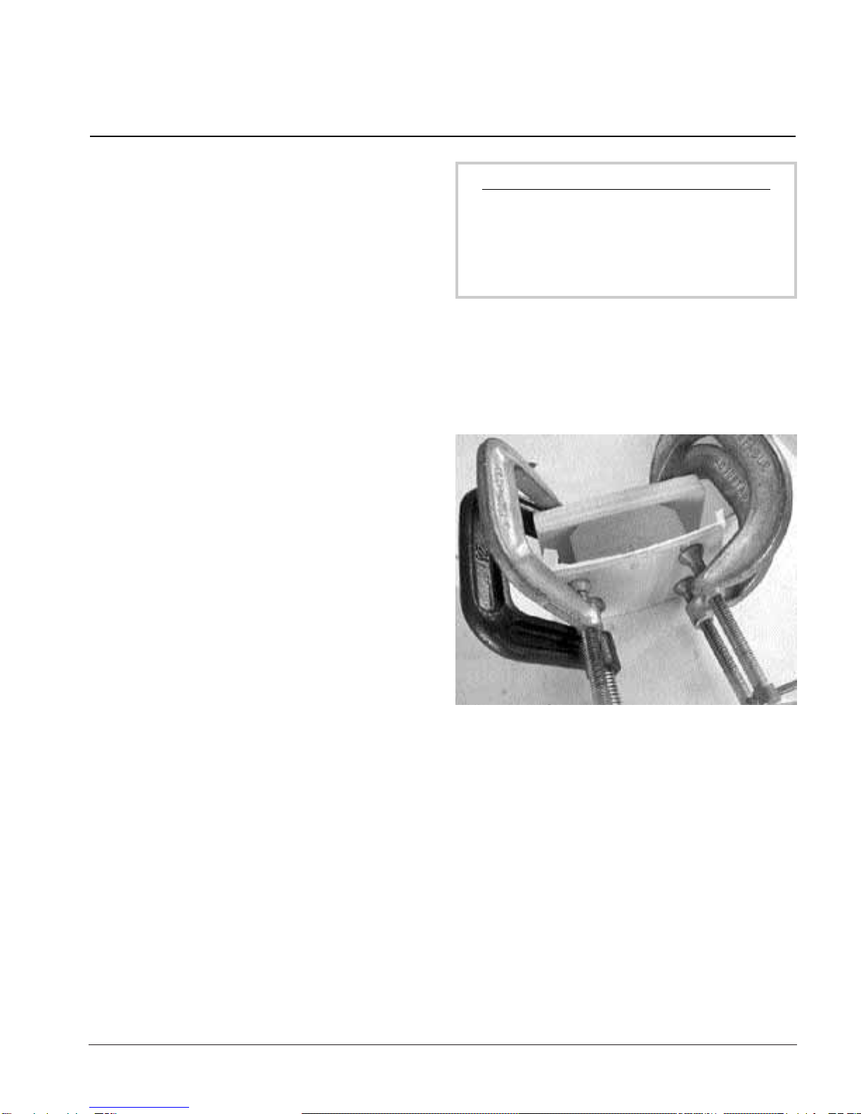
the tail block is radiused. The simplest clamping caul for
squeezing the sides against the radiused tail block is a scrap
of 1/4" plywood or wall paneling as the outer curved caul,
and a scrap wood caul on the backside of the tail block.
The neck block and tail block have beveled corners on their
inner sides. The inner backing caul at the tail block should be
wider than the block itself so the clamps put pressure where
it’s needed to pull the sides into the curve (1). The 1/4" outer
caul, being longer than the block, flexes and forms the sides
to the block. A layer of wax paper between the sides and the
caul will keep them from being glued together accidentally.
During gluing, the neck block and tail-block should rest flat
on the work surface, and flush with the face down top edge
of the sides. A weighted block of wood laid across the sides
helps keep them flat on the table during gluing.
TIP: Use a glue brush
Applying glue with a brush eliminates most of the
glue squeeze-out because the brush spreads just
the right amount of glue. We use are flux brushes,
inexpensive hardware store items used in plumb-
ing. Or, you can spread the glue with your finger!
After the neck and tail blocks are installed and the glue has
dried, use a 9/32" drill bit to drill through the sides to open
up the neck block’s bolt holes. Clamp a piece of scrap wood
over the sides before drilling to minimize tear-out as the bit
breaks through the fragile side wood.
Assembling the body
Gluing the sides to the neck block and tail block
1. The simplest clamping caul for squeezing the sides against the
radiused tail block is a scrap of 1/4" plywood or wall paneling as the
outer curved caul, and a wooden caul on the backside of the tail
block.
Install the waist clamp from the backside of the guitar. (Later,
after the top’s installed, you’ll switch the waist clamp to the
top side). When sliding the waist clamp on, hold the guitar
sides tight against the cardboard form to avoid cracking the
sides. If the fit is too tight, remove small amounts from each
side of the U-shape until the waist clamp slides snugly onto
the waist, but not so tightly that it’s hard to remove.
page 4
The two pieces of heavyweight cardboard supplied with the
kit are for creating a guitarmaking form to support the body
during the early stages of building.
Using the paper pattern, cut two matching pieces in the
shape of the guitar body. Cut carefully on the lines of the pat-
tern, leaving no extra cardboard outside the lines.
Build the cardboard form inside the guitar body. First, place
two scraps of 3/4" plywood onto the work surface inside the
guitar. This will lift the cardboard form up to make room for
the kerfed linings, which will be installed later. Lay the first
cardboard piece onto the 3/4" plywood inside the guitar
body.
Next, glue several 3/4" thick blocks of scrap wood onto the
cardboard, and then glue the second piece of cardboard
onto them. Now the two cardboard forms are fastened
together with blocks of wood between them, creating a
three-dimensional form for supporting the guitar sides (2).
Now use the paper pattern to make the U-shaped “waist
clamp” from 3/4" plywood. The purpose of the waist clamp is
to hold the guitar’s waist tight to the inner cardboard mold,
maintaining a constant shape until the back is glued on.
Use a file to smoothly round the two inner edges of the waist
clamp. Square edges wouldn’t slide over the tight curve of
the guitar sides at the waist, and they could crack the wood.
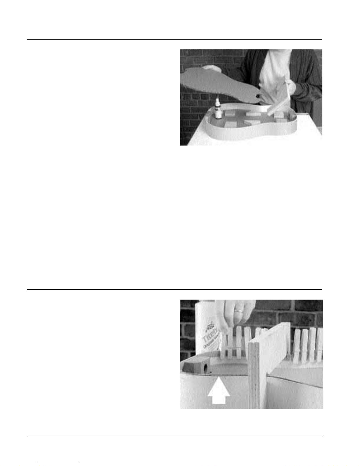
With Titebond glue, and clothespins as clamps, install the
kerfing on the top and back. The kerfing should start at the
inner edge of the neck block and run to the inner edge of the
tail block. Leave the kerfing raised slightly, approximately
1/64", above the side’s edges, both top and back (3). This
guarantees that the kerfing will be flush with the top edge of
the sides after sanding (as described next), and makes up for
any possible misalignment during gluing. In guitar building
it’s safest to err slightly on the high side — you can always
remove wood, but it’s hard to put it back! Let the glue dry at
least 4 hours.
Installing the kerfed lining (“kerfing”)
2. The two cardboard forms are fastened together with blocks of
wood between them, creating a three-dimensional form for sup-
porting the guitar sides.
Making the inner-body form and waist clamp
3. The kerfing is installed with 1/64" exposure above the side's
edges.
page 5
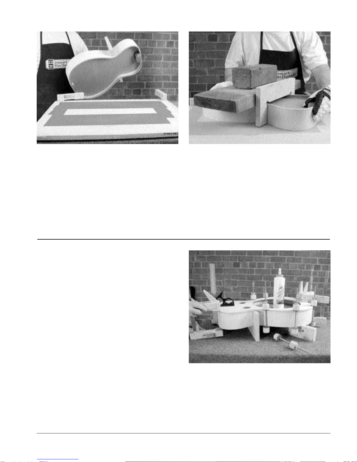
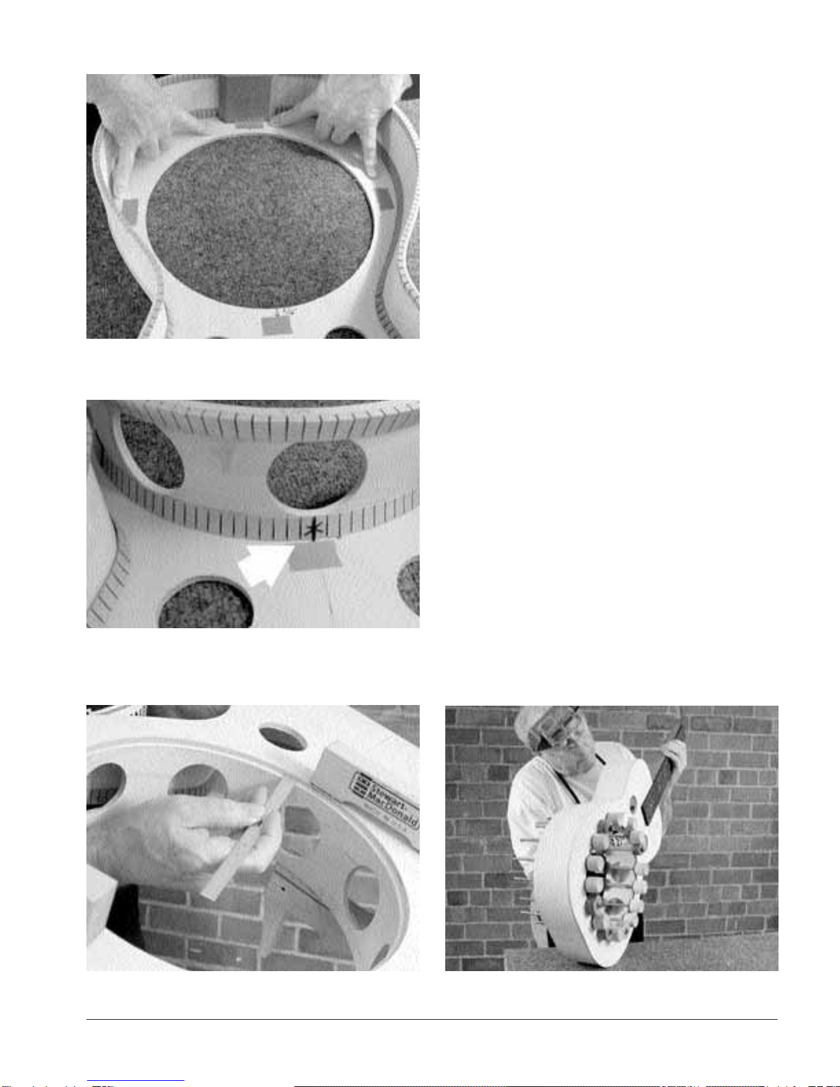
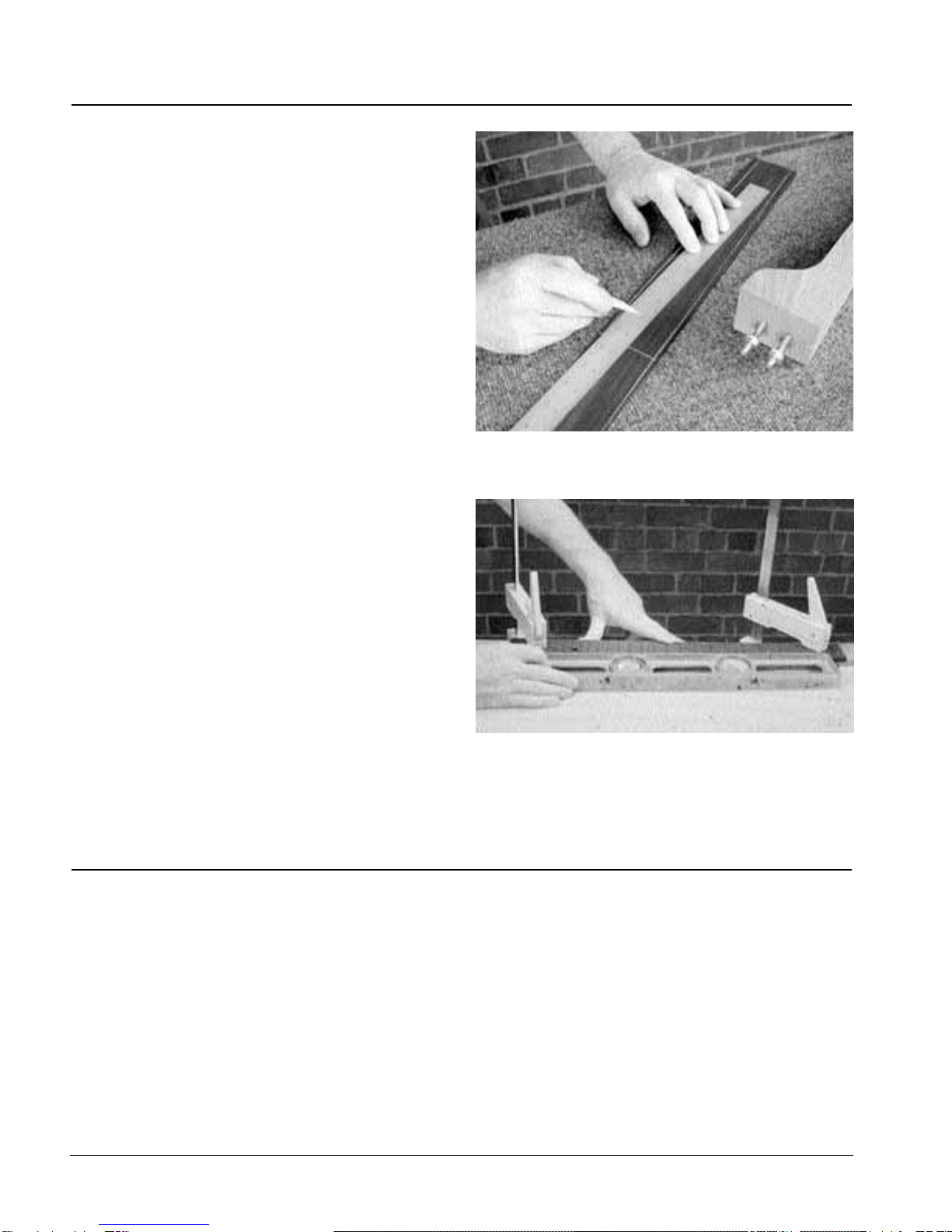
Apply adhesive-backed 80-grit sandpaper (or non-stick sand-
paper and double-stick tape) to an area of the workboard as
shown in the picture (4). Don’t cover the entire board, just a
large enough area so that the kerfing and sides contact the
sandpaper as you move the side assembly, face down, in
small circles to level the kerfed lining. Mark the gluing sur-
5. Try using a weighted board placed across the top side of the rim
for uniform downward pressure.
Choose the best looking surface of the guitar top as the out-
side surface. There two small centering holes at each end of
the guitar top. Center a long straightedge on these holes,
and lightly pencil an erasable centerline on the top.
Next, glue on the top. The most important thing you must do
is to line up the front (machined) edge of the top with the
sides at the neck block. The top and sides must be flush
there. This alignment locates the soundwell, and with it,
accurate intonation. There should not be ANY top overhang
in this area! (If, by accident, you glue on the top so that it
overhangs the sides at the neck block read “Appendix 2:
Intonation Check” at the end of these instructions before
continuing.)
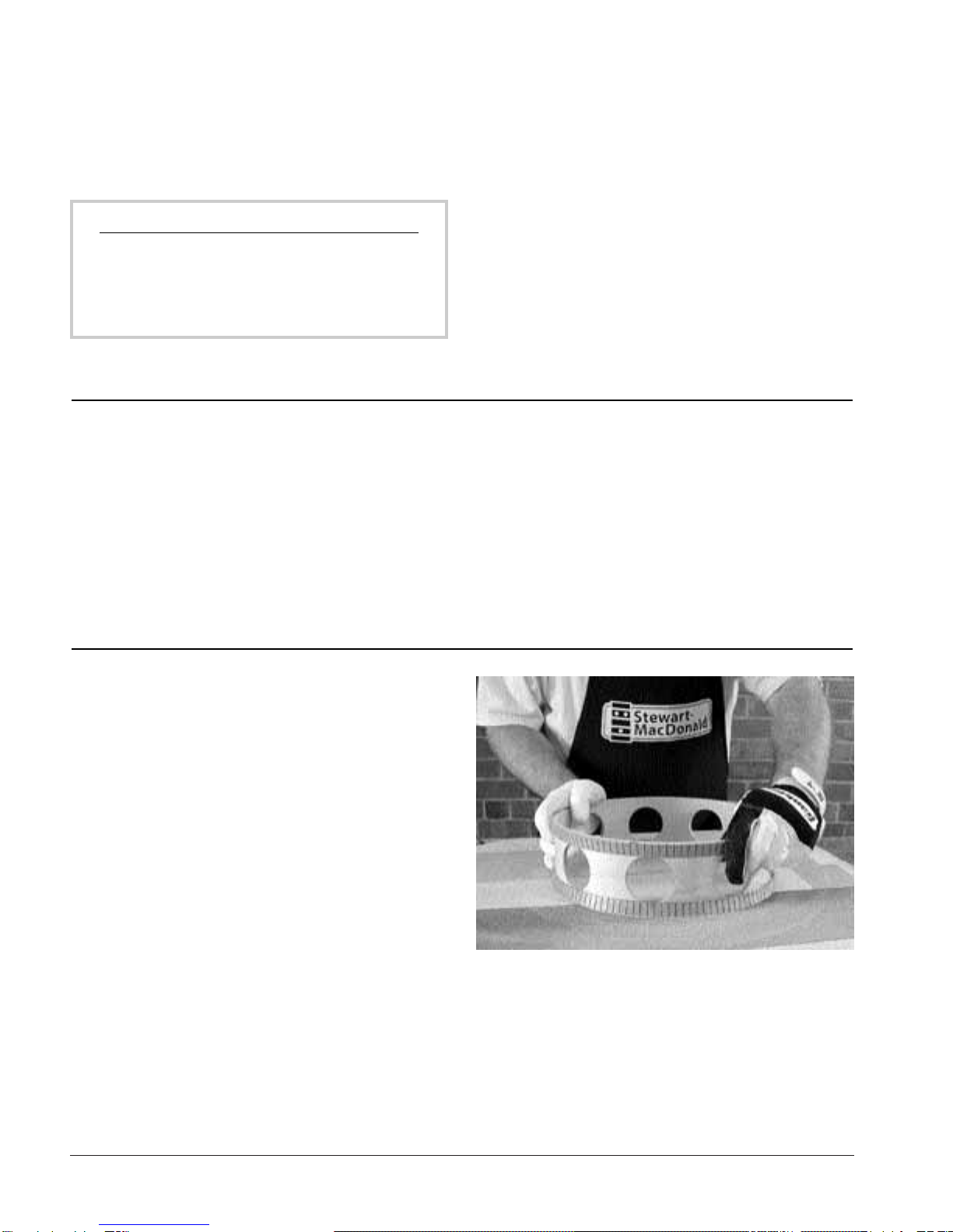
With the waist clamp still installed from the rear, line up the
top’s centerline with the centerlines you drew on the neck
and tail blocks. Start clamping in the waist area, within sever-
al inches of either side of the waist clamp, using spool clamps
to gently hold the top in place (6). Clamp the tail block, using
two cam clamps or bar clamps and a caul to spread the
clamp pressure. Next, clamp the neck block. Use an accurate
square to be sure that the neck block is square to the top as
you clamp. Use the same type of clamps and caul that you
Installing the top
4. Apply adhesive-backed 80-grit sandpaper (or non-stick sandpa-
per and double-stick tape) to an area of the workboard.
faces of the sides, kerfing, neck block, and tail block all the
way around with a pencil. Check your sanding progress
often; when the sandpaper begins to remove the pencil
marks around the entire top, the kerfed lining will be level
with the sides. Try using a weighted board placed across the
top side of the rim for uniform downward pressure (5).
6. Start clamping in the waist area, for several inches to either side
of the waist clamp, using spool clamps to gently hold the top in
place.
page 6
used on the tail block. Follow with spool clamps spaced
evenly around the sides. With spool clamps close on either
side of the waist clamp, you should have good glue squeeze-
out at the waist. Leave the waist clamp in place, and let the
glue dry at least 5 hours.
TIP: Spool clamps
Spool clamps can be made using 8" all thread rods,
wing nuts, drilled wooden spools and cork or
leather lining pads. They’re also available in our
catalog.
Remove the waist clamp temporarily to make room for a
router. With the top glued on, notice that the sides have
gained great stability, even with the waist clamp removed.
Use a flush-cutting ball-bearing router bit to remove the top
overhang in the waist clamp area (any slight burnish marks
left by the ball-bearing will sand off easily). Later, after the
back is glued on, you’ll remove the rest of the top overhang.
For now, the top overhang will match the back overhang,
making it easier to align the spool clamps.
Since you need to remove the cardboard inner form before
you can install the soundwell, sand the back kerfing now
while the body is still relatively rigid.
Re-install the waist clamp from the top side. Place the guitar
on the sandpaper workboard with the back side down. Sand
the back kerfing flush just as you did the top, until the sand-
paper just “kisses” the penciled edge of the sides.
Sanding the back kerfing
The edges of the soundwell connect the top and back, and
kerfing is needed on these edges to provide enough gluing
surface. Install kerfing on the outside of the soundwell, once
again raised a slight 1/64" above the edge (7) for flush-sand-
ing on the flat sanding board. Flush-sand only one kerfed
edge of the soundwell — the edge that glues to the top —
and then flush-sand the back edge after the soundwell is
glued to the top. Sanding the soundwell kerfing in two
stages lets you carefully flush-sand the well with the back.
7. Flush-sand only one kerfed edge of the sound well — the edge
that glues to the top — then flush-sand the back edge after the
sound well is glued to the top.
Installing the soundwell
page 7
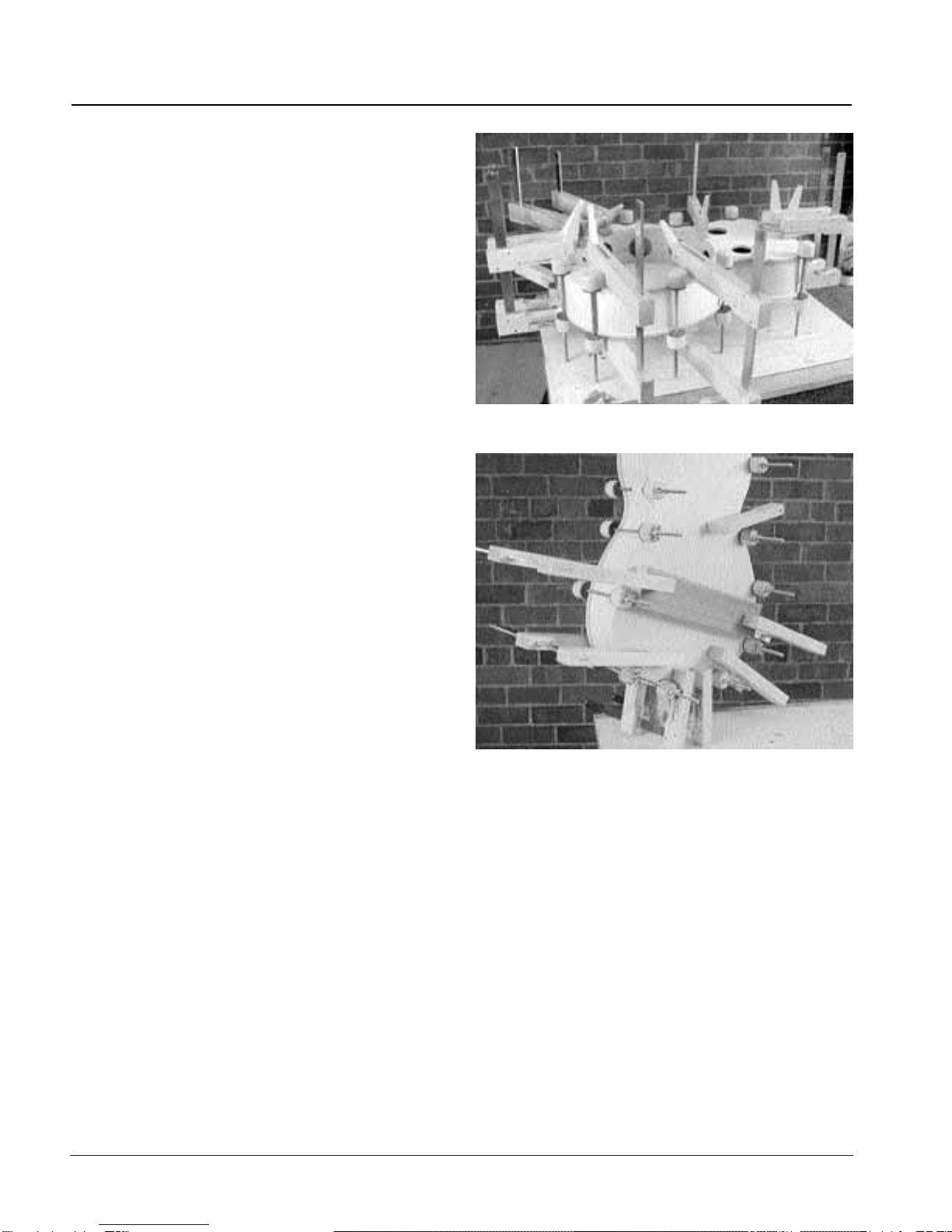
To align the soundwell concentrically with the hole in the
top, measure 5/16" out from the edge of the hole at four
opposite points, and place a piece of tape at each point as a
marker (8). The soundwell should be installed with one of
the soundwell’s “tone holes” (air-movement holes) in line
with the center of the guitar top — this hole provides access
for your wrench when you bolt on the neck. The soundwell’s
kerfing should almost touch the four masking tape markers
for alignment (9). The 5/16" measurements will leave about a
1/16" gap exposed between the outer edge of the kerfing
and the tape.
Important: Dry-clamp the soundwell to the top, and check to
see that the exposed ledge created by the edge of the
soundwell measures the same all around the hole in the top
(10). This ledge supports the cone and the spider; it’s not
very wide, so you must carefully center the soundwell when
gluing.
When the top/top alignment looks right, and is still dry-
clamped in position, pencil a mark around the kerfing on the
inside of the top as a quick reference for gluing the parts
together. Apply Titebond glue, and clamp the soundwell to
the top with spool clamps (11).
9. The sound well should center with an approximate 1/16" gap
exposed between the outer edge of the kerfing and the masking
tape.
8. Masking tape placed at four opposite points helps you align the
sound well.
10. This ledge supports the cone and the spider; it’s not very wide,
so you must carefully center the sound well when gluing.
11. Apply Titebond glue, and clamp the sound well to the top with
spool clamps.
page 8
With the soundwell glued to the top, the body assembly is
now very stable, and you can remove the waist clamp. Mark
the soundwell edge and the kerfing with pencil, and sand it
as you did the top and back. Put pressure in the center over
the soundwell, and not on the outer edges. You’ll sand away
the pencil marks quickly, so don’t work too hard!
To check that the soundwell is level with the back kerfing,
rest the body face down on your bench and place a straight-
edge across the soundwell kerfing. Rotate the straightedge
in a complete circle on the soundwell, and watch the gap
between the straightedge and the back kerfing: you’ll see
where it doesn’t touch the back kerfing. Perhaps those areas
will need a little extra pressure as you sand — mark them
with pencil as you did the top and back, and watch for the
pencil marks to disappear as you sand. Check your progress
until the straightedge contacts the side kerfing and the
soundwell kerfing evenly. The body is ready for the back to
be glued on.
At this point, you should have retained squareness between
the top and sides. Squareness is especially important at the
neck block in order to have the right playability later. If you
are out of square now, it can’t be by much. If you are, make a
note of it and adjust for that when you glue on the back, by
pushing or pulling the neck block and sides into square.
Install the back as you did the top. You don’t need the waist
clamp, but it won’t hurt to use. Start clamping at the waist
and sides, glue the tail block first, and the neck block last
(12). This is your last opportunity to square the neck block to
the top if needed.
To add extra pressure in the soundwell area, clamp a flat
board across the back (13). A little glue squeeze-out is a sign
that you have a good glue joint.
When the glue has dried, use the flush-cutting router bit to
trim the overhang from the top and back.
12. A good back clamping setup.
Installing the back
13. To add extra pressure in the sound well area, clamp a flat board
across the back.
page 9
The binding supplied with your kit measures approximately
1/4" x .060". Use StewMac’s Binding Router Cutter Set, with
the largest ball-bearing installed (14). This setup will rout a
ledge of approximately .060" for the binding width. Set the
height of the router bit’s cut at 15/64", or slightly more than
the thickness of the plywood guitar top/back, so the binding
hides the laminated edge of the plywood.
Rest the router squarely on the guitar’s top or back, and rout
a clean ledge for the binding. Be careful along the edge of
the soundwell because the router could tip easily with such
a small surface to rest on. It’s a good idea to practice routing
on scrap plywood or other wood to get a feel for the router
bit’s cut.
14. Set the height of the router bit’s cut at 15/64", or slightly more
than the thickness of the plywood, so the binding hides the lami-
nated edge of the plywood.
One strip of binding is not long enough to go completely
around the guitar, so you must use two strips and bind one
half of the top or back at a time. Bind both halves of the top
first, to practice getting a tight seam where the two bindings
meet. (The seam between the top bindings will be hidden
by the tailpiece, but on the back side the seam will show.)
With clean hands and careful work, it’s possible to produce
an invisible glue line between two pieces of binding by melt-
ing the seam together with Weld-On 16, the solvent-based
glue recommended for this work.
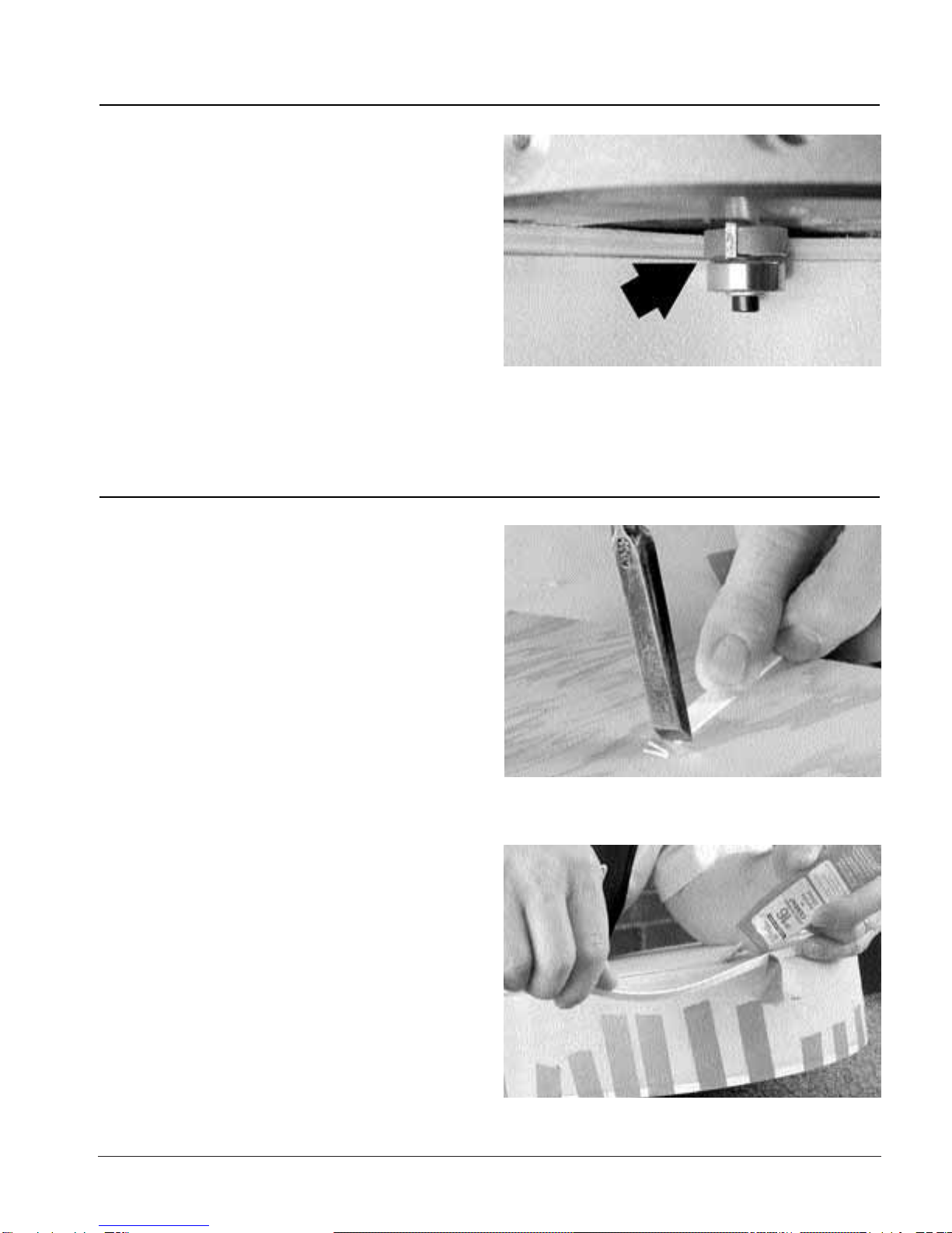
Start binding at the center seam of the tail block end. Trim
the binding square at the starting point (15) so that the butt-
jointed seam between the two halves is tight. Use Weld-On
16 glue in the channel and strong masking tape to hold the
binding in place. Weld-On 16 glue sets quickly, so glue and
tape in three or four short sections, working toward the neck
block (16).
Let the glue dry 24 hours before removing the masking tape.
Pull the tape off at a 45° angle to lessen the chance of pulling
up wood fibers. If you heat the tape lightly with a hair dryer
held 8 inches away, it will soften the sticky tape and allow it
to pull free easily.
Routing for binding
Installing the binding
15. Trim the binding square at the starting point so that the butt-
jointed seam between the two halves is tight.
16. Apply glue and tape, working in short sections.

page 10
When the tape’s removed, the binding will be slightly taller
than the routed channel. Use a sharp scraper to flush the
binding to the wood. Be careful not to dig into the top or
back as you scrape (17).
The router bit will cut slightly deeper than the actual thick-
ness of the binding — perhaps by as much .007" — so don’t
be surprised if the binding’s not quite flush to the sides (18).
The extra depth makes up for any slight unevenness that
may result from hand-held routing.
Scrape the wood to meet the binding all around the sides
(19). Combine scraping with sanding, using a backing block
and 150-grit Fre-Cut® sandpaper. Try to sand only the wood,
not the binding, since 150-grit sandpaper will leave scratch-
es. When close to being flush, switch to 220-grit Fre-Cut®
sandpaper, and sand the sides, back, and top smooth. The
top and back are made from high quality plywood, and other
than cleaning up marks that you make with tools, the ply-
wood requires very little finish sanding.
Before final sanding, use a flat block and 100-grit Fre-Cut®
sandpaper to flatten only the area of the sides at the neck
block where the flat “cheeks” of the neck heel will mate with
the sides (20). (Think of the end of the neck heel, where it
meets the guitar sides, as having two surfaces called “cheeks”
— a treble cheek and a bass cheek — i.e. a cheek on each
side of the mounting bolts that are on the centerline.) Clean
up any coarse sanding marks with 220-grit.
17. Use a sharp scraper to flush the binding to the wood. 18. The router bit will cut slightly deeper than the actual thickness
of the binding — perhaps by as much .007".
19. Scrape the wood to meet the binding all around the sides.
20. Use a flat block and 80- or 100-grit Fre-Cut®sandpaper to flat-
ten only the area of the sides at the neck block where it mates with
the flat cheeks of the neck.
page 11
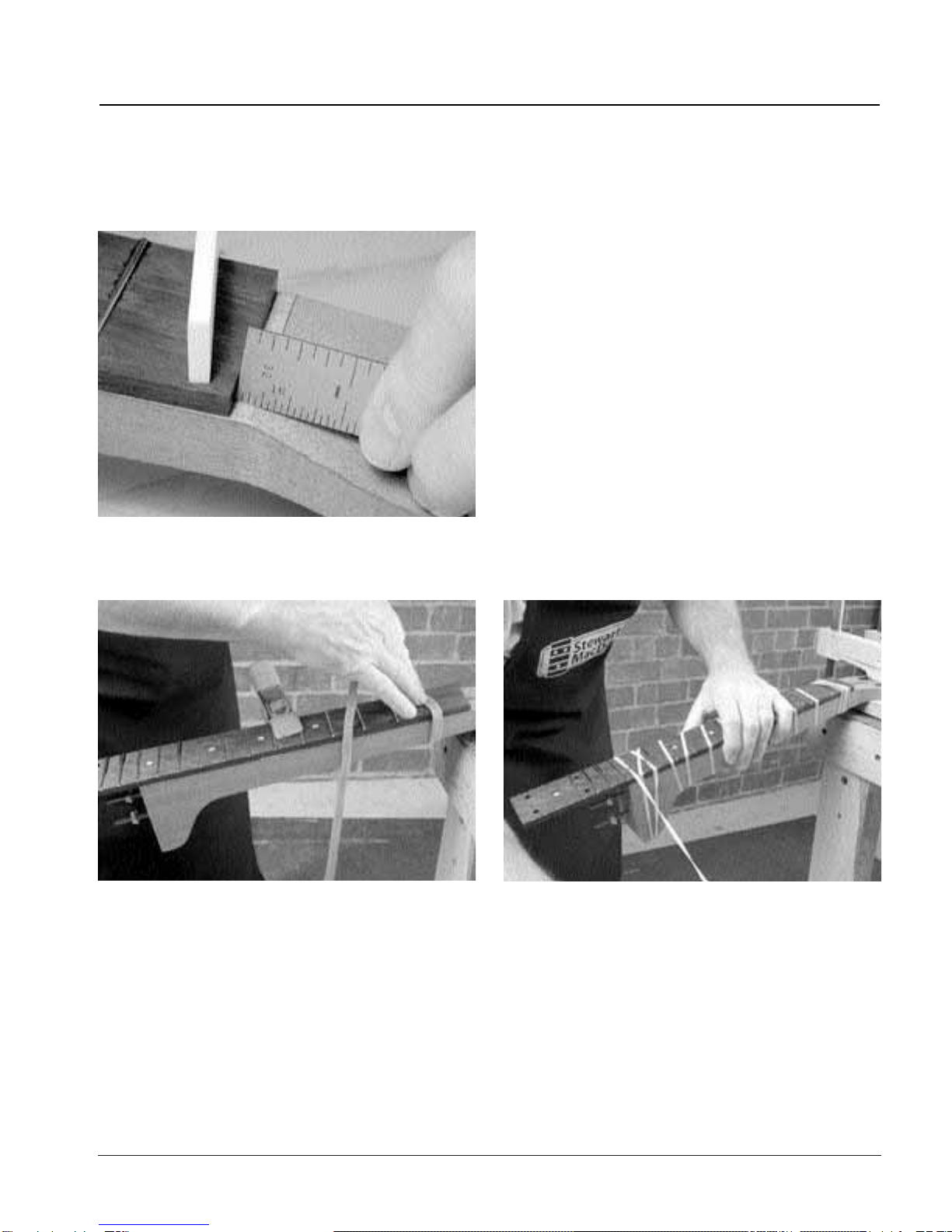
The truss rod is installed so that it adjusts at the peghead
end. This makes it easy to adjust the truss rod under string
tension.
Roll the rods simultaneously between your thumb and fin-
gers to adjust them until the thread in the upper half of the
brass lug (the rod without the adjusting nut welded to it) is
flush with the face of the lug, and not protruding excessively.
Align the back edge of the adjusting nut with the break line
of the peghead angle. (21). This locates the front edge of the
truss rod’s brass lug just under the end of the fretboard. A flat
area of approximately 7/32" will remain between the end of
the fretboard and the break angle of the peghead — this is
where the bone string nut will be installed.
The adjusting nut is slightly wider than the slot machined
into the neck. Chisel a slight clearance in the slot walls until
the adjusting nut fits to the bottom of the channel.
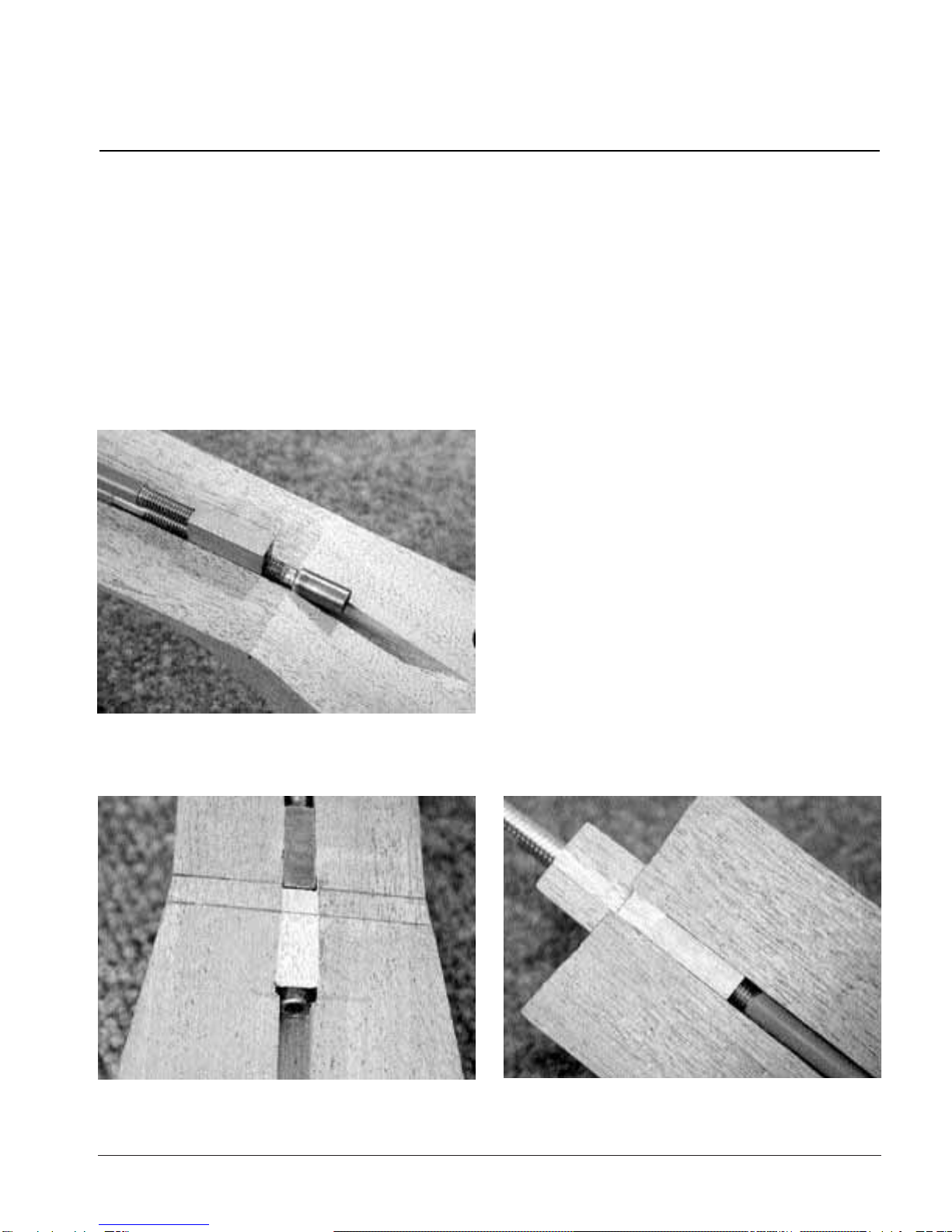
Install the rod, adjusting nut facing down. Glue in a piece of
the supplied filler strip over the adjusting nut (22) and the
exposed truss rod threads, between the brass lug and the
rear of the adjusting nut. The filler strip will support the bone
string nut, which will be installed later. Of course, keep glue
off the truss rod threads. When the glue is dry, chisel the filler
strip flush with the surface of the neck. Glue a filler strip at the
opposite end of the rod too, to fill the remaining empty
channel, and trim it flush (23).
Assembling the neck
Installing the truss rod
21. Align the back edge of the adjusting nut with the break line of
the peghead angle.
22. The filler strip will support the bone string nut, which will be
installed later.
23. Glue a filler strip at the opposite end of the rod too, to fill the
remaining empty channel, and trim it flush.
page 12
The fingerboard has 24 fret slots, more than are needed for a
resonator guitar. Trim off the fingerboard at the 20th fret slot.
Draw a pencil line across the back of the fingerboard to mark
the location of the 12th fret slot. The end of the neck’s fin-
gerboard gluing surface, at the top of the heel, will line up
with this mark when the fingerboard is glued on. Align the
heel with the mark, center the neck on the fingerboard, and
draw the profile of the neck onto the fingerboard (24).
Extend the lines using a straightedge and white or yellow-
lead pencil.
Trim the fingerboard profile close to the pencil lines using a
band saw, coping saw, or a hand plane.
The edges of the fingerboard must be smoothed after
they’re trimmed. On your flat work surface, rest the finger-
board, backside down, on a spacer block approximately 1/4"
thick and as long and wide as the fingerboard. Slide the fin-
gerboard slightly off the edge of the spacer block so that one
long edge overhangs.
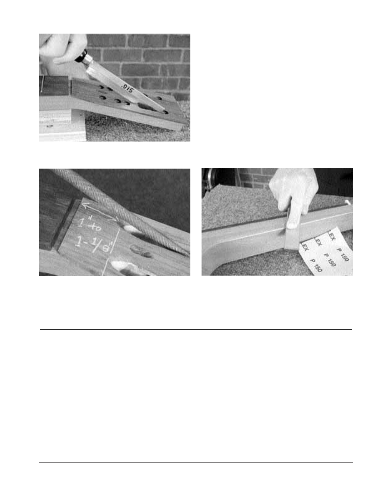
With a long flat sanding block, sand the overhanging fret-
board edge lengthwise to remove any trimming marks. We
used a carpenter’s level with 100-grit sandpaper double-stick
taped to its thin edge. Clamped and sanded in this fashion,
the fretboard will not only be straight end-to-end, but the
edge will be sanded at 90° to the work surface as well (25).
Reverse the procedure for the other edge of the fingerboard.
Clamped and sanded in this fashion, the fretboard will not
only be straight end-to-end, but the edge will be sanded at
90° as well.
Traditionally, single dot inlays are installed behind frets 5, 7, 9,
12, 15, 17, and 19. Frets 15 and 19 get two inlays each. These
will cover the four mounting screws that hold the finger-
board to the top. You won’t inlay frets 15 and 19 until later,
after the guitar is finished.
Lightly draw a centerline down the fingerboard in pencil. Use
an awl to mark for drilling along this centerline, measuring
halfway between the appropriate frets.
Drill 1/4" holes for each inlay, using a brad-point drill bit. Go
slightly deeper than the thickness of the dots. Be extremely
careful to keep the drill bit from“hogging”into the wood and
accidentally drilling all the way through (practice on scrap)!
As mentioned, frets 15 and 19 are drilled for double inlays.
They’re spaced 1-3/8" apart (11/16" to each side of the cen-
terline), and centered between the frets.
Shaping the fingerboard
Inlaying the fingerboard
24. Draw the profile of the neck’s taper onto the fingerboard using
a white pencil.
25. Clamped and sanded in this fashion, the fretboard will not only
be straight end-to-end, but the edge will be sanded at 90° as well.

page 13
Within the four 1/4" holes, just barely start a secondary hole
with a 7/32" twist drill (not a brad-point) (26). These sec-
ondary holes bevel the bottom of the 1/4" holes to form the
right shape for the fingerboard mounting screws. These
holes are difficult to drill without overdoing it, so practice on
scrap! This chamfering is very delicate; the slightest turn of
the drill bit will produce the desired shape.
Next, drill 1/8" holes through these chamfered holes at frets
15 and 19 for the four mounting screws to pass through the
fingerboard during final assembly.
Put on your protective safety glasses! Then, one at a time,
place a drop of medium-viscosity superglue in each drilled
hole and set the dot inlay in place. By using a piece of clear
acrylic as a caul (lightly waxed with paste-wax), you can
apply pressure without sticking to the superglue, and still be
able to see when the inlay is flush. Remember not to inlay at
frets 15 and 19! You may need to tap gently on the caul with
a hammer to seat the dot inlays. Don’t overdo the superglue,
and you won’t have a messy fretboard to clean up. Flush the
inlays to the fingerboard using a smooth mill file and a sand-
ing block. Sand equally from end to end so you don’t change
the flat surface of the fretboard.
A 1/16"-diameter plastic dowel is included with your kit for
making side dot fret position markers along the bass edge of
the fingerboard (for right-handed players, that is). Install
them now at frets 5, 7, 9, 12, 15, 17, and 19. The 12th fret often
gets two dots, spaced evenly between the 11th and 12th
frets, but some makers use only one. Often, side dots are not
used past the 12th fret — the choice is yours.
Clamp the fretboard on edge, mark the centers of each hole
with an awl, and carefully drill the holes with a sharp 1/16"
drill bit. Drill square to the fingerboard edge at all times.
Nip short lengths from the plastic inlay dowel and superglue
them into the drilled holes — they should extend out slight-
ly above the surface. When dry, file and sand the dots
smooth.
TIP: Smooth side dots
Clamp the fingerboard back on the spacer block
used earlier for truing the edge of the fingerboard,
and re-sand the edges lightly with the carpenter’s
level and 220-grit sandpaper.
Installing side dots
26. Create chamfers within the four 1/4" holes using a 7/32" twist
drill.
page 14
A scrap piece of unfretted fingerboard has been included
with your kit. Measure out the frets you will actually use on
your fretboard, and use the leftover fretwire to test your skills
on the scrap.
Drill 19 holes in a block of scrap wood to keep the frets in
order as you cut them to length. Using flush-cutting fret nip-
pers, cut the pre-radiused fretwire to length, allowing an
overhang of 1/8" on each side of the fingerboard.
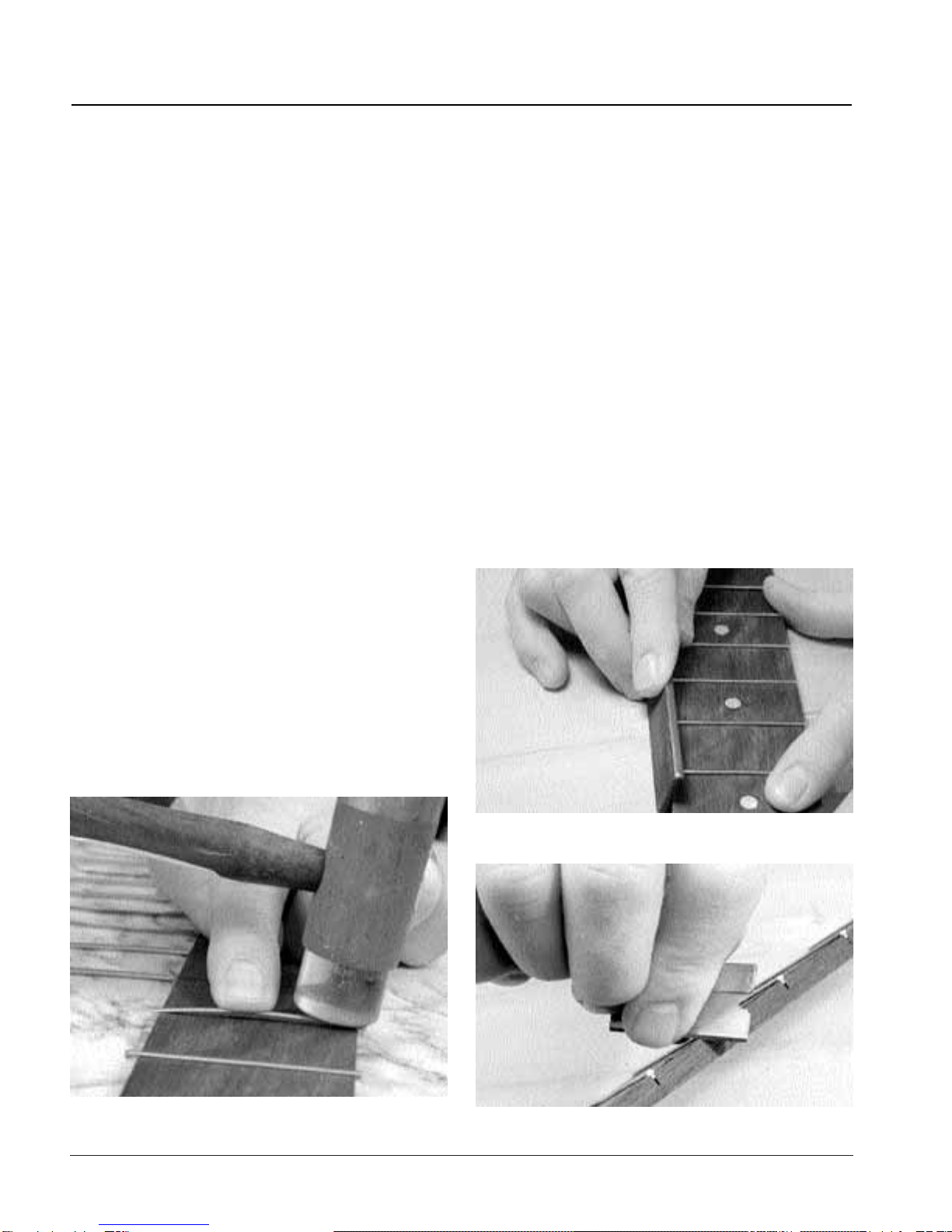
Clamp the fretboard flat to a solid surface. We fretted on a
flat, 1-1/4" thick chunk of marble —a piece of plywood rest-
ing on a cement floor would work well, too. Set the fretwire
on the slot; since it’s curved, only the ends will enter the slot.
With your finger, balance the wire to keep it from tipping and
prying up a chunk of wood as you tap the two ends into the
fret slot with a hammer (27). Once the two fret ends are
embedded in the fret slot, the fret is unlikely to tip as you
hammer it home.
Hammer back and forth across the fretboard in short, sharp
blows. Use the face of the hammer, not an edge, and try not
to hit the fretboard on either side of a fret. The fret tang, with
its diamond-shaped barbs, embeds itself into the finger-
board as the fret straightens end-to-end from the hammer
blows.
Test to see that the frets are seated well by prying on an
overhanging end with your fingernail. Loose frets can be
firmed up with superglue run into one end of the fret slot.
Keep the fretboard tilted at an angle to keep the glue from
getting onto the fretboard. Or, an option is to tape off the
fretboard on each side of a slot and run a bead of Titebond
into the slot before hammering in the fret. If you use
Titebond, let the frets dry overnight before nipping and filing
their ends.
When the frets are firm and the glue is dry, nip them almost
flush with the fingerboard edge. Do not nip right up to the
edge, or the nippers will pull into the fingerboard and possi-
bly unseat a fret end.
Use a smooth mill file to flush the fret ends to the edge of the
fingerboard. Then use the same file, held at an angle, to file
the fret-end bevels (28). Choose a bevel that suits you —
perhaps between 45° and 60°. Stop when the file hits the
wood.
Blunt the top edges of the fingerboard on the bass and tre-
ble sides with a single-edge razor blade (29). Later, when you
glue on the fingerboard using a rubber band clamp, there
will be no sharp edge to break the rubber band.
The fingerboard is now ready to be glued to the neck.
Fretting the fingerboard
27. Keep the wire from tipping and prying up wood as you tap the
two ends into the fret slot with a hammer.
28. To bevel the fret ends, use a smooth mill file held at an angle.
29. Blunt the sharp top edges of the fingerboard on the bass and
treble sides with a single-edge razor blade.
page 15
There should be a flat area approximately 3/16" to 7/32" wide
left between the end of the fingerboard and the break angle
of the peghead. This is where the bone nut will rest (30).
Install the fingerboard with Titebond glue. To get just the
right glue coverage, spread it with a flux brush. Work the glue
up to the edge of the truss rod channel, and then draw it
away from the edge with the flux brush to keep glue
squeeze-out from getting into the channel.
Place the fingerboard onto the evenly-glued neck surface
and center the 12th fret slot directly over the edge of the
neck heel. Hold the fingerboard in place temporarily with a
spring clamp (31) as you start to wrap with the rubber bands
supplied with your kit. Tie the rubber band at the peghead
and wrap from end-to-end and back again. Get plenty of
wraps on the heel (32). You may find that one rubber band is
all that’s needed for the job. You can a shift the fingerboard
slightly from side-to-side as you wrap, but usually the board
will center itself nicely.
Installing the fingerboard
30. The bone nut will rest on the flat area approximately 3/16" to
7/32" wide, left between the end of the fingerboard and the break
angle of the peghead.
31. Hold the fingerboard in place temporarily with a spring clamp
as you start to wrap with the rubber bands supplied with your kit.
32. Get plenty of wraps on the heel.
page 16
When the fingerboard’s dry, remove the rubber band clamp.
The bone nut blank should be smooth-walled, square-bot-
tomed, and of uniform thickness. If it needs smoothing or
thicknessing, sand it with 100- and 220-grit sandpaper, dou-
ble-stick taped to a flat surface.
Place the nut blank on the flat ledge that remains between
the end of the fingerboard and the break angle of the peg-
head. File or sand a 14° angle on one end of the peghead
overlay so that it butts flush and tight up to the back edge of
the nut (33). Once the overlay is glued on, the space
between the overlay and the fingerboard will be a perfectly-
sized channel for the nut.
Dry-clamp the overlay in place. With a pencil, mark a point 1-
9/16" from the back edge of the nut, centered on the
peghead’s width. Drill a 1/4" hole at that point. This is the
access hole for the truss rod.
Remove the clamps from the overlay. Hold the overlay in one
hand and elongate the hole by slowly tilting the overlay
against a running drill bit (34). You may want to practice this
on a piece of scrap (there’s plenty of excess overlay that gets
trimmed away, so practice on that). You’ll end up with an
elongated access hole for the 1/8" Allen wrench that adjusts
the peghead.
Mark the peghead shape on the overlay. Trim away most of
the excess, to within 1/8" all around the peghead. Use pro-
tective cauls on the face and rear of the peghead, and glue
on the overlay. Keep the overlay pressed tightly against the
nut during alignment.
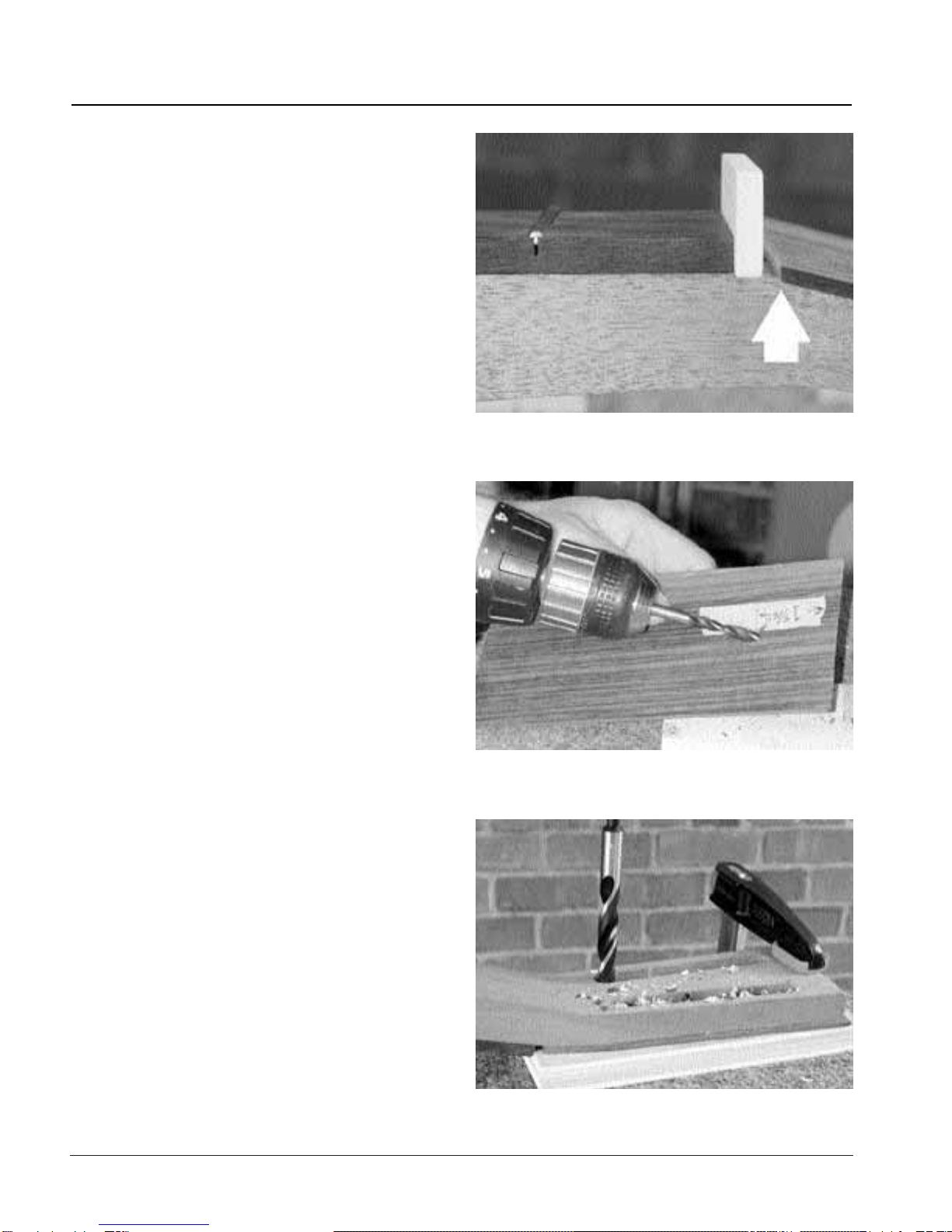
When the glue’s dry, clamp the peghead firmly, face down,
on a scrap of plywood. Use a 7/16" bit to drill holes against
each end of the tuning machine channels (the channel will
keep the drill bit lined up), and then drill several holes in
between these holes in the remainder of each channel (35)
to eliminate as much of the wood as possible.
Installing the peghead overlay
33. File or sand a 14° angle on one end of the overlay so that it fits
flush and tight to the nut.
34. Hold the overlay in one hand and elongate the hole by slowly
tilting the overlay against the running drill bit.
35. Use a 7/16" drill bit to drill holes against each end of the tuning
machine channels.
page 17
Saw, chisel, and file away the chaff left by drilling, until the
channel walls are smooth (36). Then carve and file ramps at
the nut end of each channel, so the strings don’t rub the
wood on their way to the tuning posts. The shape of the
ramps is up to you, but they extend approximately 1" to 1-
1/8" from the back side of the nut (37).
Carve and file away the overhanging peghead overlay, and
then sand the peghead face and sides smooth with 150-grit
Fre-Cut® sandpaper.
Use a file and sandpaper to round off the square machined
edges of the neck and heel (38). Leave the neck mostly the
way it is supplied, in the traditional squared-off style of the
instrument.
The tuner holes are pre-drilled with a distance between the
tuning post centers of 1-3/8". This is a common measure-
ment, and a variety of tuners will fit this hole spacing.
Set the tuners in the peghead, and use an awl or other sharp
tool to mark the mounting screw holes. Remove the tuners,
and drill the holes with a 1/16" bit. Mark the drill bit with a
piece of masking tape as a depth stop.
You may need to cut off the end of the tuner mounting
screws if they’re too long for the thin outer walls of the slot-
ted peghead. First use the untrimmed screws to “tap” the
thread for each hole, and then cut their ends off and install
the tuners temporarily, so you can fit the neck to the body.
Fitting the tuning machines
36. Saw, chisel and file away the chaff left by drilling, until the
channel walls are smooth.
37. Carve and file ramps at the nut end of each channel so the
strings don't rub wood on their way to the tuning posts.
38. Use a file and sandpaper to round off the square machined
edges of the neck and heel.
page 18
The guitar must be assembled and set up completely before
applying a finish, and then dismantled for finishing.
Place the neck mounting bolts through the neck block holes
in the body. Press the heel against the shoulders, and then
hold the neck in place as you install the two hex nuts. Tighten
the hex nuts just snug enough to hold the neck, because you
may need to move the neck a little.
Don’t use a socket wrench with a right angle drive to tighten
the nuts onto the neck bolts — you could get too much
torque and possibly crack the heel, or pull a bolt out of the
heel!
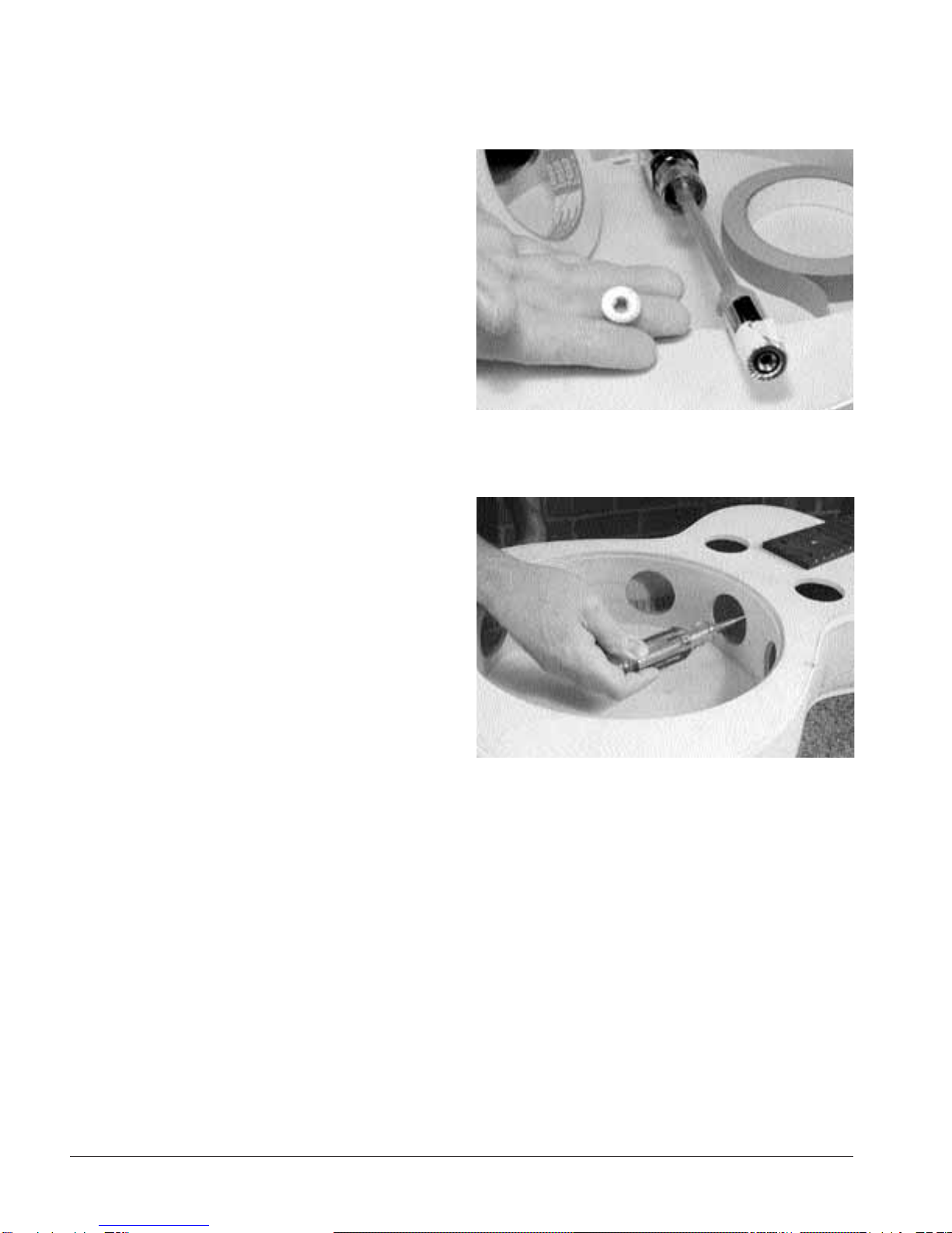
Instead, make your own nut driver as we did. We made a
long-handled nut driver from a deep-well, square-drive 7/16"
socket, and a #3 Phillips screwdriver that fit the 1/4" drive per-
fectly (39). Use tape to hold the socket onto the screwdriver
shaft (or do a little grinding and the screwdriver tip will force
in there permanently).
Also use a small piece of tape to hold the hex nut into the
socket as you reach into the body to start the nut onto the
bolt. Don’t over-tighten the nuts — the amount of pressure
you can apply with your thumb and fingers is probably
plenty (40).
Check that the neck is on center to the top’s centerline by
holding a long straightedge against the edges of the finger-
board and extending to the tail block. Do this on both the
bass and treble sides, one edge of the fingerboard at a time.
Make pencil marks representing this fingerboard projection,
and then measure in from each mark to the center. Ideally,
these two measurements will be the same. Our treble side
was about 1/32" too close to the center, so we removed the
neck and used a rat-tail file to slightly enlarge the holes in the
neck block. This allowed us to move the neck over a tiny bit
toward the treble side.
Final assembly and setup
39. We made a long-handled nut driver from a deep-well, square-
drive 7/16" socket, and a #3 Phillips screwdriver that fit the 1/4"
drive perfectly.
40. The amount of pressure you can apply with your thumb and
fingers is probably plenty.

page 19
For a more accurate neck alignment check, you must install
the cone, spider, saddle, tailpiece, and the two outside
strings. Before installing the cone, scrape off any glue residue
from the soundwell rim where the cone will rest, so the cone
will seat on a flat surface. Set the cone on the rim. Rotate it
until you find the point where it rocks the least; this is the
cone’s “sweet-spot.” Use a felt marker to mark the front of the
cone on center, pointing directly toward the neck (41).
The legs of a new spider are seldom perfectly aligned when
resting on a flat surface. They need to be adjusted to fit. Using
double-stick tape, fasten four pieces of 3/4" plywood in a rec-
tangular pattern on your flat workboard, as shown in the
photo. Space the blocks so the spider’s legs are in contact
with the upper surfaces of the blocks, and then fasten 80-grit
sandpaper to these surfaces with double-stick-tape.
With a black felt marker, blacken the underside of the spider
on every leg (42). You can follow your sanding progress by
watching the ink on the feet. One good sanding technique is
to sand in small circles; another good technique is to use a
clockwise/counterclockwise turn of the wrist in a short,
abbreviated motion. Use even pressure when sanding the
legs, until all the marker is removed (43). The metal dust on
the sanding blocks will show you which feet need the most
attention.
Fitting the cone
Truing the spider’s “legs”
41. Set the cone on the rim. Rotate it until you find the cone’s
“sweet-spot.” Mark the front of the cone with a felt marker.
42. Blacken the underside of the spider on every leg.
43. Use even pressure when sanding the legs, until all the marker is
removed.
Table of contents
Other Stewart MacDonald Guitar manuals


