Stewart MacDonald 5297 User manual
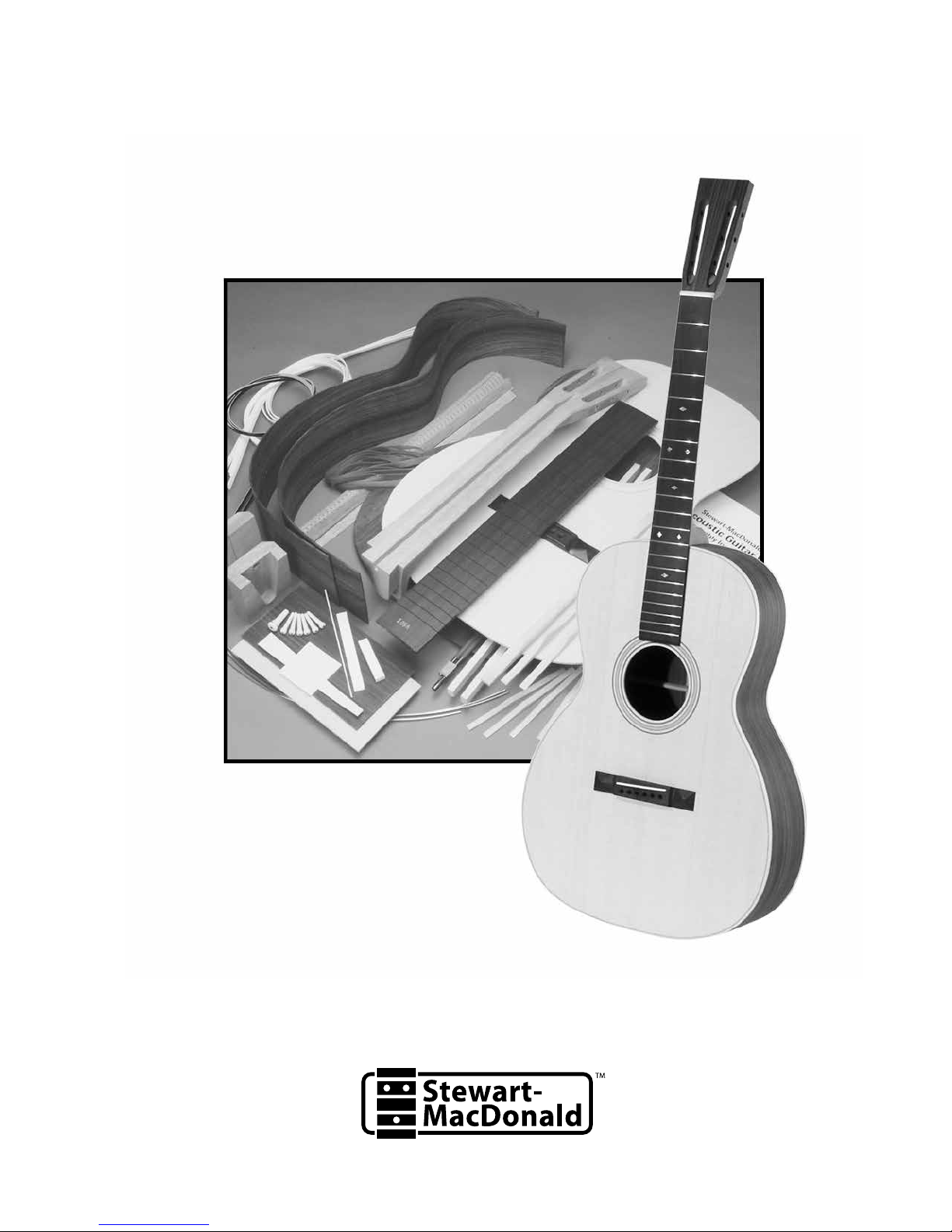
Triple-O
Acoustic Guitar Kit
#5297 Assembly Instructions
www.stewmac.com


Getting started
Welcome to guitar building! ....................2
Recommended tools and supplies ...............2
Kit parts list .....................................3
Side Assembly
Assembling the sides ...........................4
Making a body mold ............................5
Installing kerfed linings .........................6
Squaring the neck block and tailblock ...........6
Leveling the kerfed linings ......................7
Soundboard bracing and fitting
Installing the soundhole rosette .................8
Shaping the X-braces............................8
Installing the soundboard bracing ..............8
Bridge and shoulder brace clamping cauls .......10
Fitting the soundboard to the sides .............10
Opening the dovetail joint ......................11
Installing the soundboard .......................12
Back bracing and fitting
Installing the back bracing ......................13
Fitting the back to the sides .....................13
Installing the side reinforcing strips .............14
Installing the back ..............................14
Routing and binding
Trimming the top and back overhang ...........15
Routing for the plastic body bindings ...........15
Shaping the heel cap and end trim ..............17
Installing the end trim ..........................17
Installing the bindings ..........................17
Fit and fill the truss rod channel
Fitting the truss rod .............................18
Fill the channel..................................18
Peghead shaping and drilling
Peghead overlay ................................19
Shape the peghead .............................19
Making a fretboard
Trimming the fretboard .........................20
Inlaying the fretboard ...........................20
Installing the fretboard side dots ................21
Installing the frets ..............................21
Installing the fretboard .........................22
Neck shaping and fitting
Shaping the neck ...............................23
Installing the nut ...............................24
Fitting the heel cap .............................24
Understanding the neck joint ...................24
The neck heel sets the neck angle ...............25
Fitting the neck to the body .....................25
Neck adjustment: side-to-side ...................26
Neck adjustment: tilt the neck back .............26
Neck adjustment: tilt the neck up ...............27
Tightening the dovetail joint ....................27
Installing the last frets ..........................27
Finishing
Introduction to finishing and materials ..........28
Sanding the body ..............................28
Filling the fret ends .............................29
Sanding the neck ...............................29
Spray handles and hangers .....................29
Masking the neck and body .....................29
Staining ........................................30
Applying a washcoat to seal the wood ..........30
Filling the wood grain pores ....................30
Lacquer spraying schedule ......................30
Sanding and rubbing-out the finish .............31
Final assembly and setup
Prepare for neck installation ....................32
Install the neck .................................32
Prepare for bridge installation ...................33
Installing the bridge ............................34
Fitting the bridge pins...........................34
Fitting the bridge saddle ........................34
Installing the tuning machines...................35
Seating the strings ..............................35
Understanding neck relief ......................35
Adjusting string action: nut slots & saddle height 36
Leveling the frets ...............................37
Installing the endpin ............................37
CONGRATULATIONS! ...........................37
Table of contents

stewmac.com
Small cam clamps (at least 2) #3724
Large cam clamp (2) #3725
Spool clamps (24) #3715
Clothes pins (50)
Medium bar-style clamp (2) #3714
X-Acto knife
Small carpenter’s square
Feeler gauges #1811
Supplies
3/4" plywood workboard 24" x 20"
Titebond glue #0620
Weld-On Cement #1975
Super Glue (#0010 thin and #0020 medium)
Double-stick tape #1689
Low tack protective tape #1682
Masking/binding tape (high tack) #0677
Rubber binding bands #1256 (option to using binding tape)
Sandpaper (80, 100, 150 and 220-grit)
Wax paper
White pencil
Felt-tip marker
Capo #4571
Clean cotton glove
Finishing materials (for aerosol nitrocellulose lacquer finish)
Guitar Finishing Step-By-Step book #5095
Fre-Cut® sandpaper 150, 220, 320, 600, 800, and 1200-grit at least 2 sheets
of each grit (included in Finishing Paper Sampler Package #5562)
ColorTone Concentrated Liquid Stain (tobacco brown #5034, red
mahogany #5032)
Grain filler
ColorTone Clear Gloss aerosol nitrocellulose lacquer (6) #3881
Blush Eraser #1313
Stewart-MacDonald Polishing Compound medium #1845 and fine #1846
Stewart-MacDonald Swirl Remover #1847 (optional)
Foam Polishing Pads (2 or 3) #3414 and electric hand drill
Naphtha solvent #0775
Paint stripper
Masking supplies: brown paper, masking tape, cardboard and
rubber balloon (or newspaper) for soundhole
The following tools and supplies are recommended to as-
semble your kit. Though all of these tools aren’t necessary
to build your kit, they make many assembly steps easier
and more professional. Where applicable, item numbers for
ordering from Stewart-MacDonald are included.
For binding installation, you have a couple of different
options to choose from depending on the tools you already
own. If you plan on using a laminate trimmer or router for
binding channels, we suggest our Binding Router Bit (#1298-
B) and bearings (#1298-060, 1298-100). It is our preferred
method. If you plan on routing your binding channels with
a Dremel tool, our Precision Router Set (#5263) ships with
everything you will need.
Tools
Electric hand drill
Coping saw
Center punch or awl
Glue brushes #4167
6" Steel rule #4894
1/2" Chisel #1623
File set #0842
Small rasp #4154
Fret Leveler #0862
Dressing stick #1939
Fret cutter #0619
Deadblow fret hammer #1296
18" Straightedge #3850
.020" gauged saw #3572
Scraper blade #0654
4mm Allen wrench #6113
Nut-slotting files: 0.016" width (#0827) and 0.035" width (#0832)
1/4"-diameter bit #4850
Bridge pin reamer #3227
Fret dressing file, medium # 1602
Radius-sanding block, 16" radius #0413
Recommended tools and supplies
daily to neutralize excessive warping. Depending upon your
location and the season, you may need to humidify or dehu-
midify your shop to maintain the desired relative humidity.
It is advisable to purchase a thermometer/hygrometer to
monitor your shop’s climate. If you’re unable to control the
relative humidity in your shop, we discourage building the
guitar during the transition from dry to wet seasons, or vise
versa. The radical change in humidity can cause warping,
splitting or other serious complications.
Throughout the assembly of the kit you’ll need a flat
workboard of 3/4" plywood approximately 24" long and 20"
wide, big enough for your guitar’s body assembly.
Be safe when using tools, glues, and chemicals. Wear
eye protection and gloves when needed, and always
use proper ventilation.
You are about to build a truly great guitar! We designed this
kit with the small shop builder and a modest tool budget in
mind, with the exception of a few specialty guitar making
tools.
Please read these instructions before building your guitar.
Some photos in these instructions use a Dreadnought gui-
tar as a model, though the technique is the same for either
Dreadnought or Triple-O guitar. Options include dovetail or
bolt-on neck and back and side woods of either mahogany
or rosewood.
It’s very important to acclimate the wood to your building
environment. The ideal building environment temperature is
70-80° Fahrenheit (21-26° Celsius), with a controlled relative
humidity of 45-50%. The kit wood should be laid out and al-
lowed to “equalize” for one week in your shop. Flip the wood
Getting started
Welcome to guitar building!
Stewart-MacDonald
has easy-to-order sets
of tools that kit builders
find most useful, search
“acoustic kit tools” at
stewmac.com
2

stewmac.com
1Bent sides, rosewood or
mahogany, depending on
your kit (2)
2Kerfed lining (8)
3Fretboard
4Mahogany neck, dovetail
or bolt-on
5Rosewood peghead overlay
6Maple bridge plate stock
7Neck block, dovetail or
bolt-on
8 Tailblock
9 Thick binding, black or white
10 Thin binding, white and black
11 Sitka spruce soundboard
12 Bridge
13
Back, rosewood or mahogany
14 Building an Acoustic Guitar Kit
DVD
Kit parts list
15 Blueprint, body and bracing
patterns
16 Heel cap and end trim
17 Herringbone rosette (3 pieces)
18 Top brace set, plus 2 unshaped
X-braces
19 Fretwire (3)
20 Bone saddle blank
21 Bone nut blank
22 Diamond shaped inlays,
small (4), and large (3)
23 White side dot material
24 Back brace set (9 pieces)
25 Endpin
26 Bridge pins (6)
27 Hot Rod truss rod
28 Reinforcement strips (3)
29 Shim stock (not in bolt-on kit)
Not pictured: this assembly
instructions book, cardboard
body mold (2), scrap wood,
and large rubber band
12
3
4
5
6
7
8
9
10
11
12
13
16
14
15
17
18
19 20
21
22
23
24
25 26
27
28
29
3

stewmac.com
Save the cardboard box your kit came in. Cut away the
sides of the box and use the large top and bottom to create
a double-thick cardboard surface on your workboard.
Each bent guitar side has been formed from a tapered piece
of wood. One of the longer edges is straight (the guitar top)
and the other is slightly curved (the back). Place the sides,
straight edges down, on the cardboard and butt the ends
together. The sides shouldn’t rock on the workboard surface.
Pencil accurately measured centerlines on the neck block
and the tailblock, and align these marks against the inner
seams of the adjoining guitar sides. The open top of the
neck block must face downward against the workboard,
and both blocks must be flush with the sides at the top and
bottom.
Dry-clamp the two blocks to the sides, place a piece of wood
across the waist, and rest a weight (a couple of bricks worked
for us) on the piece of wood (pictured) to keep the sides
flat against the cardboard. Now readjust the neck block and
tailblock while the sides are weighted down.
KIT TIP: Dry clamping
It’s important to try fitting and clamping the kit
pieces before you use glue. Practice a “dry run” to
make sure you have all the clamps and cauls needed
before glue is applied. We found that using a little
brush (like our Glue Brush) helps to apply the glue
evenly on the surface.
The neck block is beveled on the surfaces which will contact
the top and back of the guitar. The back side of the neck
block has a fairly steep 5° angle to match the arch of the back;
the open top of the neck block has a shallower 1-1/2° taper.
Trace around the neck block onto the cardboard, and use a
sharp knife to cut along that line through the first layer of
cardboard. Don’t cut the front edge where the block meets
the guitar sides. This allows you to compress the cardboard
downward to make clearance for the 1-1/2° taper of the
neck block as you press it down against the flat surface of
the cardboard. Viewed from the side, in cross-section, both
ends of the neck block are flush where they meet the sides,
but are higher than the sides as they taper up toward the
interior of the guitar.
The side of the neck block that touches the guitar sides is
curved. A clamping caul with matching curvature (illus-
trated) should be prepared from scrap wood and placed
against the outer side seam. The same caul will fit both the
neck block and tailblock areas.
KIT TIP: Cauls
You’ll need scrap wood to make cauls that will be
used throughout assembly. Cauls are used to ap-
ply uniform pressure while the glue dries, and to
protect the guitar’s surface from the clamps.
Remove the clamps and, one at a time, apply Titebond glue
to the inner block surfaces. Reclamp using four clamps per
block. Wipe off the excess glue with a damp cloth and let
the assembly dry overnight before unclamping. Use waxed
paper to prevent the wooden parts from being glued to the
cardboard surface.
Side Assembly
Assembling the sides
Clamping caul with
curved face
Use
waxed
paper to
protect
guitar
sides
Use four
clamps
Cut the
corrogated
board to fit
the angled
face of the
neck block
Neck
block
5° taper for back
1-1/2° taper for top
Some photos will use a Dreadnought guitar as a model, though the
technique is the same for either Dreadnought or Triple-O guitar.
4

stewmac.com
Using the two heavy cardboard body forms (supplied with
the kit) create a guitarmaking form which supports the body
during the early stages of assembly.
First, place two scraps of 3/4" plywood onto the work surface
inside the guitar. This will lift the cardboard form up to make
room for the kerfed linings which will be installed later. Lay
the first cardboard piece onto the 3/4" plywood inside the
guitar body.
Next, glue a 1-1/4" tall block of scrap wood onto the card-
board, centered about 4" from the smaller end of the guitar
mold. Then glue a second 1-3/4" tall piece of scrap wood,
centered about 4" from the bottom (larger end) of the guitar
mold. Glue the second piece of cardboard onto them. Now
the two cardboard forms are fastened together with blocks
of wood between them, creating a three-dimensional form
for supporting the guitar sides.
Make a U-shaped waist clamp from 3/4"-thick plywood, using
the waist clamp measurements (illustrated). The purpose
of the waist clamp is to hold the guitar's waist tight to the
inner cardboard mold, maintaining a constant shape until
the back is glued on.
Use a file to round the two inner edges of the waist clamp
to remove edges and protect the guitar sides.
To start out, install the waist clamp from the back side of
the guitar. (Later, after the top is installed, you'll switch the
waist clamp to the top side) When sliding the waist clamp
on, hold the guitar sides tight against the cardboard form
to keep from cracking the sides. If the fit is too tight, remove
small amounts from each side of the U-shape until the waist
clamp slides snugly onto the waist (but not so snug that it's
hard to remove).
Making a body mold
Rounded
edge
Waist
clamp
3/4"
Blocks:
1-1/4" tall
1-3/4" tall
Corrugated
cardboard
9-1/4"
6"
2"
2"
13-1/4"
Waist Clamp
Made from 3/4"-thick plywood
5

stewmac.com
Eight kerfed (notched) wooden lining strips, or “kerfing”,
are supplied for reinforcing the glue joints between the
soundboard, sides and back. Dry-clamp (no glue) the kerfing
strips to the top edge of the side assembly using ordinary
spring-tension clothespins (pictured). Each side of the gui-
tar requires two strips, which should be accurately trimmed
where they meet the body blocks. Use at least four or five
dozen clothespins. The top (gluing) surface of the kerfings
should extend 1/32" above the edge of the guitar’s sides, on
both the top and back sides. The kerfing is left slightly tall
so that you’ll have a little wood to sand off until the kerfing
comes perfectly flush with the top edge of the sides, and
to make up for any possible misalignment during glue-up.
Disassemble, trim the linings, glue them into place with
Titebond, check the 1/32" clearance and reclamp. Let the
glue dry for 4 hours. Install the kerfing strips on the back
edge of the side assembly in the same manner.
Installing kerfed linings
Squaring the neck block and tailblock
Although they work quite well, the waist clamp and card-
board inner body mold still allow some movement. Handle
the rim assembly carefully, especially until the top and back
are glued on and the assembly becomes more rigid. Lay the
rim assembly topside-down on the plywood work surface,
weight it down again, and use a square at each end to see
if the neck block and tailblock are square to the plywood
surface. If either end is slightly out of square, use a thin ta-
pered wedge pressed between the cardboard inner body
mold and either the neck block or tailblock as needed, to
force the blocks and sides into square (pictured). Having
the sides properly squared up at this stage is important.
Stewart-MacDonald’s tool recommendation
Titebond Glue Item #0620
The luthier’s favorite aliphatic resin glue, for joints that are stronger than the wood.
Water soluble, it cures overnight, sands easily, and resists thermoplastic “creep”
better than ordinary white glues.
6

stewmac.com
Prepare a “sanding board” from a straight flat piece of wood
about 3-4" wide, at least 1" thick, and 24" long (illustrated).
Add a wedge on each side of one end of the sanding board.
These wedges will tip the sanding board to match the angles
of the top and back as you sand the kerfed linings, neck and
tailblocks. The wedges should be approximately 8" long, and
as wide as the sanding board. Make one wedge 5° for the
back linings, and the other 1-1/2° for the top linings.
Rest the side assembly, with the straight top edge down,
on the flat surface of your workbench. The front shoulders
should overhang the bench, so that the waist clamp can be
fastened to the edge of the benchtop with two wood screws.
If you’re unable to screw the waist clamp to the bench, clamp
a board flush to the bottom edge of your bench, and clamp
or screw the waist clamp to the board.
Draw a white pencil line on the edge of the guitar sides to
serve as an indicator of your sanding progress. Stop sanding
when the line is gone and you begin to graze the sides. Us-
ing double-stick tape, attach 80-grit sandpaper to the side
of the sanding board with the 5° wedge. Hold the wedged
end of the board against the tailblock as a pivot point, and
begin sanding the neck block and the front shoulder area
first. Work around the sides to the tailblock, moving the
pivot point frequently, until the sandpaper begins graz-
ing the white pencil marks on the top edge of the sides. It’s
easy to oversand the sides and the kerfed linings, leaving the
neck block or tailblock higher than the sides, and causing
a “hump” in that area later. Keep this in mind, and give the
blocks a little extra sanding. White pencil them several times
and use a straightedge to be sure they are flat.
Move the waist clamp to the back side of the rim assembly,
and refasten the clamp to the bench with the top kerfed lin-
ings facing up. Repeat the sanding process, using the 1-1/2°
wedged side of the sanding board. The top kerfed linings
have a slighter bevel and are easier to sand than those on
the back of the rim. When your sanding reaches the white
pencil line, the linings are ready for the guitar top to be fitted.
KIT TIP: Back kerfing
The back kerfed linings can be level-sanded AFTER
the top is glued to the sides. The rigidity added by
the glued top makes the sanding easier and more
accurate. If you choose this option, level the top
kerfed linings first (pictured), then sand the back
linings just before removing the cardboard inner
mold.
Leveling the kerfed linings
1-1/2° wedge
for sanding top edge
5° wedge for
sanding back edge
Sandpaper
on both sides
Sands the kerfing
at the angle
of the tapered
block
7

stewmac.com
Glue the purflings in place with Titebond and press them
firmly into the channels. A flat clamping caul covered in wax
paper will seat them well. After drying, scrape the purflings
flush to the surface of the soundboard, using a sharp scraper
blade. Flex the scraper slightly as you work, and trim the
purflings until the tool begins to pick up bits of spruce.
Soundboard bracing and fitting
Installing the soundhole rosette
Installing the soundboard bracing
Three bent wooden purflings form the soundhole rosette.
The two narrow rings composed of parallel black and white
strips install in the inner and outer rings of the rosette, and
the wide decorative ring goes in the middle channel.
The purflings are longer than needed, to enable the removal
of the straightened ends on each ring left from the bending
process. Dry-fit the three rings in their channels. Trim the
ends closely at a slight angle to compensate for the curve of
the channel. The outer and center ring joints will be hidden
under the fretboard, so you don’t have to be too critical with
the fit of the ends. However, be careful to trim the inner ring
accurately, as it will be exposed. Trim the outer and center
rings first for practice, and then concentrate on the inner
ring. A few extra minutes of careful work here will make a
big difference in the appearance of the final instrument.
Pencil the soundboard bracing pattern (pictured) on the
inside surface of the soundboard (cut small holes in the brace
pattern at the corners and intersections of the braces, lay
the pattern on the soundboard, transfer the hole positions
in pencil, and “connect the dots” on the soundboard when
the pattern is lifted away). The pattern MUST be correctly
centered along the soundboard’s center seam, with the
soundhole properly located. Note that the soundboard and
the back have been trimmed to allow about 1/8" overhang
all around. This offers a little freedom when assembling the
top and back to the rim, and will be trimmed away later.
Shaping the X-braces
Braces in our Triple-O and Dreadnought kits are nearly iden-
tical, with the exception of the X-braces. In the parts of this
Triple-O kit you will find both.
X-braces for Dreadnought
Discard
X-braces for Triple-O
Carve these according to the blueprint,
to use in your Triple-O guitar
The longer, shaped X-braces are used when building a
Dreadnought guitar, and not in the building of your Triple-O.
They are to be used as a visual aid only, then discarded.
The uncarved X-braces are to be carved according to the
blueprint and used in your Triple-O guitar.
The radiused edge (bottom) of the uncarved X-braces is
to be glued onto the soundboard. Round over the straight
(top) edge of these two braces to resemble the X-braces for
the Dreadnought set, but carve the scalloped curves and
notches as illustrated in the blueprint. Use a file, plane and/
or sandpaper.
8

stewmac.com
The two long X-braces (T-1 on the blueprint), the tall front
shoulder brace (T-5), and the tone-bars (T-2) are radiused.
The flat shoulder brace and the four small braces (T-3) are
not radiused.
With the soundboard face down on your workboard, place
these two X-braces on the penciled lines and mark where
they cross. With a razor saw, notch the radiused T-1 braces
so they interlock. Using the rigid workboard, dry-clamp the
ends in place, flat to the soundboard (pictured). Clamp
the center of the “X” down, using one or two long cam
clamps. The combination of the curved braces and the rigid
workboard will produce the proper soundboard arch (a 28-
foot radius) when the clamps are removed.
As shown in the pattern, the ends of the T-2 tone-bars, the
four small T-3 braces, and the maple bridge plate tuck under
the X-braces. File these notches in the X-braces at a 45° angle
(pictured). Using a sharp chisel, carefully shape a matching
angle on one end of these braces where they tuck under.
Reclamp the X-braces onto the soundboard and workboard.
Check the fit of the tone bars in the notches. Disassemble,
apply Titebond to the braces and tone bars, reclamp, and
let the glue dry overnight. This work can be done in stages,
depending upon the number of available clamps. Use
two flat clamping cauls for each pair of tone bars, with the
soundboard resting on your workboard to keep it flat at this
stage (pictured). Cut the three flat soundhole reinforce-
ment strips (T-4) to length and glue them into position on
the soundboard.
Transfer the outline of the bridge plate from the blueprint
to the flat maple bridge plate stock. Saw out the plate and
true its edges against a piece of sandpaper taped to a flat
work surface. Don’t drill the bridge pin holes yet; this will be
done later. File a 45° bevel at each end of the bridge plate
and check for proper fit in the X-brace notches. File off each
pointed end of the bridge plate so that it can slide forward
as it tucks under the X-braces. Prepare a wooden clamping
caul to fit snugly over the installed bridge plate between
the X-braces, and glue the plate onto the soundboard
with Titebond or hide glue. The lower clamp jaws should
contact the back of your workboard to protect the spruce
soundboard.
9

stewmac.com
While the braces are accessible, prepare a bridge clamping
caul and a shoulder brace caul that will be used in the “Install-
ing the neck” and “Installing the bridge” sections. The bridge
caul (illustrated) is 7-1/2" x 1-3/4" x 3/4". It must be relieved
to contact the bridge plate and the soundboard, and have
sufficient relief to clear the X-braces and the tone bars. The
easiest way to create this relief is to glue scrap corners from
the bridge plate itself onto the corners of the caul. This way,
the caul’s center portion is relieved by an amount equal to
the thickness of the bridge plate.
The shoulder brace caul is 2" x 2-5/8" x 1-1/4", with relief to
clear both shoulder braces. Use a saw and a chisel or router
to make these cauls.
Bridge and shoulder brace clamping cauls
1-3/4"
3/4"
7-1/2"
2"
1-1/4"
2-5/8"
Bridge clamping caul
These surfaces must contact the soundboard;
the notches should not contact the braces.
This surface must
be relieved to contact
the maple bridge plate.
Shoulder brace caul
5-3/8"
Body length: 20-3/8"
To fit the top, the ends of the X-braces and the tall shoulder
brace must be notched into the kerfed linings. The remain-
ing smaller braces will be tapered to nothing where they
meet the kerfing. Tapering these braces to nothing will let
the top flex a little more.
For this fitting, leave the side assembly clamped to the
workbench if you’re able to work around the assembly com-
fortably. You can unclamp the side assembly and the waist
clamp from the workbench if it makes fitting the top easier,
but be sure to handle the assembly gently. Don’t bend or
twist the sides as you fit the top.
Chisel the ends of the X-braces and tall shoulder brace down
to a thickness of .100" (pictured). Follow the pre-machined
taper of the braces as you chisel.
To find the guitar’s accurate length between neck and
tailblocks, first measure 5-3/8" from the top edge of the
soundhole, towards the neck block (illustrated). Make
a pencil mark on the centerline, on the underside of the
soundboard. Measure 20-3/8" from this mark to the tailblock
end, and make a mark. This is the body length. During glu-
ing, these marks must align with the sides and blocks. The
soundboard will overhang the sides a little, which will be
trimmed away later.
Fitting the soundboard to the sides
10

stewmac.com
KIT TIP:Trimming soundboard overhang
An option to leaving the top overhang is to remove
it in the neck block and tailblock areas only. This
gives you an opportunity to re-check the square-
ness of the sides to the top in these areas during
gluing. If you trim the overhang flush, then during
gluing, you can butt the top and sides at each end
until they are flush to ensure squareness. This way,
the top fits the sides, neck block and tailblock accu-
rately, and you can ensure that the body measures
20-3/8" from end-to-end.
Using a 3/4" x 2" x 3" scrap wood caul and two cam clamps,
gently dry-clamp the top to the neck block. Next (if nec-
essary), pull the sides and tailblock into the body length
pencil mark (look at the mark on the underside) and gently
dry-clamp that end. Don’t use excessive pressure, since the
braces to be notched will be resting on the kerfed lining at
this point. On the guitar’s sides, use a white pencil to mark
the end positions of the X-braces and the large shoulder
brace. Remove the soundboard and trace the brace posi-
tions onto the kerfed linings with a straightedge, using the
marks as reference points. For the X-braces, be sure to hold
a long straightedge between the reference points at the
proper angle. The positions of the tone bars should also be
marked if you choose to notch them. The tone bars don’t
notch in as deep as the other braces, and only a slight filing
will be needed.
With a knife and/or file, remove wood from the linings and
the sides in the penciled areas to accomodate the ends of
the braces. These notches should taper toward the interior
of the guitar to match the taper of the braces (pictured).
When the notches are cut correctly, the top will fit into place
and be ready for gluing.
Opening the dovetail joint
Before gluing on the top, remove the side wood covering
the neck joint opening in the neck block. With a sharp stiff
knife or a saw, score through the sides until the waste wood
can be snapped off up to the scored line. Follow with a sharp
chisel and a file to smooth the sides flush to the inner walls
of the dovetail.
Stewart-MacDonald’s tool recommendation
Guitar Brace Chisel Item #1615
This specially curved blade makes it easier to create the smooth curves needed for
scalloped braces and tone bars with feathered ends. Great for removing dried glue
from the sides of the braces, too. High quality steel blade and balanced wooden
handle.
11

stewmac.com
With the waist clamp still in place on the side assembly, and
with the assembly resting top-down on the flat plywood,
recheck the squareness of the neck block and tailblock to
the sides. Make slight adjustments if necessary by adding
or removing a wedge of wood between the blocks and the
cardboard. Turn the guitar over so the top faces upward.
Handle the assembly carefully now, until the top is glued on!
When gluing the soundboard and the back onto the sides,
use C-clamps, or cam clamps as pictured, at both ends,
with plenty of spool clamps in between. Carefully prop up
the backside, on each side of the waist clamp, with small
boxes, blocks of wood, or anything that will lift the waist
clamp clear of the table, to allow clamping access at each
end. When the neck block and tailblock are clamped, and a
few spool clamps are in place, you won’t need these props
anymore. The body won’t rock on the waist clamp, nor will
it lose shape from the weight of the clamps or the clamping
process. PRACTICE gluing the top in place by dry-clamping
it in the order of the steps numbered below. After doing a
dry run for practice, we suggest that you remove the clamps
— and do it again! It pays to be able to move quickly and
surely when glue is applied.
1. After aligning the centerlines and the body length pencil
lines at the neck block and tailblock, first apply two clamps
with protective cauls at the neck block end. If you trimmed
the neck and tailblock overhangs earlier, align both ends
until flush.
2. Begin installing spool clamps at the neck block, using four
clamps on each side up to the waist clamp. By gluing the
neck block and shoulder area first, the angle of the “neck set”
won’t be affected if you need to pull or push the tailblock
to the 20-3/8" mark.
3. Align the sides at the tailblock end with the body length
mark, and clamp as you did the neck block.
4. Start installing spool clamps at the tailblock; use seven on
each side up to the waist clamp.
5. Remove the waist clamp and install final spool clamps
there (pictured).
Installing the soundboard
Mark the spool clamps from 1 through 12 on each side, re-
move them, and lay them out in order for quick reclamping.
Apply glue to the kerfed linings, align the soundboard and
repeat the clamping process.
KIT TIP: Spool clamps
It’s helpful to number the spool clamps during the
dry run so they can quickly be reapplied during the
gluing process. Spool clamps can be made using 8"
all thread rods, wing nuts, drilled wooden spools
and cork or leather lining pads. They’re also avail-
able in our catalog.
Stewart-MacDonald’s tool recommendation
StewMac Spool Clamps Item #3715
Assembly clamps with a different twist! The simple spool clamp for soundboard
and back assembly, made faster and easier with a hardwood handle. (After all, glue
won’t wait forever while you fiddle with wing nuts.)
12

stewmac.com
As was done with the soundboard braces, follow the taper
and shape of the pre-machined back braces and chisel the
ends of each brace to .100" high at the points where they
will notch into the kerfed linings.
KIT TIP: Back brace caul
A notched gluing caul, made from 20" x 3/4" x 1-1/2"
scrap wood or plywood (pictured), can be placed
to one side of the back’s centerline, half the distance
of the spruce center strips. This keeps the reinforc-
ing center strips in a neat, straight line from end to
end. Use scrap wood cauls and two cam clamps for
uniform pressure on each spruce strip. Avoid glue
squeeze-out that might stick to the notched caul!
Choose the less attractive side of the joined guitar back as
the inside surface, and transfer the back bracing pattern from
the blueprint to this surface. Place the four braces in position
with their curved surfaces contacting the back, and notice
their more extreme curvature (a 20-foot radius). Unlike the
top gluing setup, a flat surface is not used as a gluing caul for
the back braces. Instead, make a radiused outer gluing caul
by tracing the outer curve of the longest back brace onto a
20" piece of scrap 2" x 4" wood (illustrated). Saw and sand
it to shape. You can make four cauls if you want to glue all
the back braces simultaneously.
After applying glue to a brace, place the caul on the outer
side and clamp the caul and the brace ends first (spring
clamps are useful for this). Add two cam clamps to reach
the center of the brace.
When all the back braces are installed, trim the spruce center
strips into five pieces of accurate length to cover the center
seam between the back braces. Glue and clamp the center
strips into place and allow to dry before unclamping.
Back bracing and fitting
Installing the back bracing
Fitting the back to the sides
Trace the curved brace onto a 2x4 and cut
on a bandsaw for a curved back-brace caul
If you haven’t yet leveled the back kerfed linings, do so now.
Use the 5° wedged sanding board.
When correctly installed, the guitar’s back will have an arch,
with curvature both longitudinally and laterally, and will
have a slight overhang of about 1/8" around the outside.
Double-check that the outside distance of the sides from
the neck block to the tailblock measures the correct body
length: 20-3/8". If it doesn’t, the lower bout and tailblock end
may have “stretched” out of shape a little. This can happen
if the assembly sits too long without a top or back, or as a
result of high humidity in your work area. The assembly can
be pulled into length as the back is glued on.
At the neck block end, trim the back’s spruce center strip until
it butts up against the inner edge of the neck block. The pen-
cil mark should line up at the front edge of the guitar at the
neck block. Be sure the penciled back outline at the tailblock
end is also exactly 20-3/8" from the neck block mark.
Place the guitar’s back assembly onto the rim assembly,
align the center seam with the side seams, butt the trimmed
spruce reinforcing strip up against the neck block, and
dryclamp lightly. Next, carefully and lightly dry-clamp the
tailblock end of the back, making sure that the body length
pencil mark aligns with the sides, and that the centerlines
match. If the sides at the tailblock don’t align with the body
13

stewmac.com
The blueprint included with your kit illustrates the positions
of the 1/4"-wide spruce reinforcement strips. Transfer the
centerlines of the reinforcement strips from the blueprint
to the inner sides of your kit. Measure, mark and cut three
strips for each side from the three 20" spruce strips supplied
with your kit. Each strip should fit snugly between the ker-
fed linings. You can taper the ends and round the two long
exposed edges of each strip for a cleaner look.
Before gluing, dry-clamp each strip to make sure it lies flush
with the guitar side. You may want to make a small caul to
help hold the strip and spread the clamping pressure, with
an accompanying outside caul for backup. Experiment with
C-clamps, spring clamps, or cam clamps until you find a com-
bination that works for you. Apply a thin bead of Titebond,
clamp the strips in place (pictured), and allow at least an
hour before unclamping.
length pencil mark on the back, gently push the sides and
tailblock slightly until the body length mark meets the sides,
and lightly dry-clamp. You may find it easier to have a friend
help in case you need to manipulate the neck block and
tailblock into shape.
Use a white pencil to mark the positions of the ends of the
Installing the back
back braces on the sides. File .100"-deep notches in the
kerfed linings and the sides to accept the braces, as you did
for the guitar top. Now, chisel the spruce center strip so it
butts against the tailblock.
When the back assembly fits correctly, cut the cardboard
inner mold into pieces with a sharp knife and remove them.
Installing the side reinforcing strips
In the waist area of the soundboard, trim away the 1/8"
overhang so the waist clamp will fit. Install the waist clamp
from the front of the guitar to hold the sides in shape while
gluing the back.
Clean up the inside surfaces of the body to remove dust and
glue. Dry-clamp the back into place with spool clamps and
cam-clamps or C-clamps, as you did for the soundboard.
Check and correct the fit if necessary, according to the
centerline and the body length marks. Unclamp, apply
Titebond to the kerfed linings and reclamp, starting at the
neck block. Follow the same clamping order as you did with
the top (pictured). Let the glue dry overnight.
Stewart-MacDonald’s tool recommendation
Acoustic Guitar Kit Clamp Set Item #5287
A set of 24 quality clamps made of hardwood and steel that you’ll need for your
acoustic guitar build. Set includes: 2 small Double Cam Clamps, 2 large Double Cam
Clamps, 4 sets of 6 StewMac Spool Clamps.
14

stewmac.com
Use a small straightedge to examine where the top and back
meet the sides. Look for dips, rises or other imperfections.
Scrape and sand the wood flat and smooth for at least 1" on
the sides and 2" or 3" on the top and back. This will provide
accurate surfaces for your router base and ball-bearing
cutter. Be particularly careful in sanding and smoothing
this area because imperfections will result in an uneven
binding channel.
Regardless of the tool you use to rout the body for binding,
a straight-cut router bit must be used to produce a right-
angle ledge. You can use a Dremel router with our adjustable
binding router attachment and 5/16" bit, if you approach
the final size slowly. We used a more powerful laminate
router of manageable size and a relatively small-diameter
baseplate. The baseplate didn’t extend far enough out on
the arched guitar back to tip it out of proper alignment with
the sides. We also used our ball-bearing Binding Router Bit
and bearings.
To keep wood dust and chips out of the shop in our video,
we moved outside and rested the guitar body on the open
top of a rectangular plastic garbage can. Hold the body
securely with your elbows as you rout. For more stability,
secure the guitar body to your plywood work surface by
screwing several close-fitting wood blocks onto the board
around the body. Thin strips of veneer or heavy cardboard
can be lightly wedged between the blocks and the body
to hold it fast. You can also use the waist clamp fastened to
your workbench for most of the routing, and remove it to
rout the waist of the body.
Wood tear-out is always possible when routing, but espe-
cially with long-grain, quartersawn tonewoods. Therefore,
start with four “climb cuts,” so-called because the router is
“climbing,” or being pulled along as the bit grabs the wood.
Begin at the centers of the top and lower bouts on both
the treble and bass sides (illustrated), with the router base
moving in the direction of the rotating cutter (clockwise).
With a saw, chisel and file, remove the section of soundboard
that covers the top of the neck joint cavity, and smooth the
edges. Routing for the body bindings is easier if the excess
top and back overhang is removed first. You’ll be able to see
the router bit better, and there’s less chance of wood tearout.
You can trim off the overhang with a sharp knife and a file,
or get in close with those hand tools and flush-cut with a
ball-bearing router bit.
Routing and binding
Trimming the top and back overhang
Routing for the plastic body bindings
Rout up to the areas indicated by the arrows. When all four
climb cuts have been made, you can move the router in the
opposite direction (counterclockwise) cutting into the wood
rather than climbing (illustrated). Make one continuous
pass around the guitar. When you reach the areas that were
already climb cut, the router will pass without tear-out.
Use a dial caliper to set your router cutting dimensions, and
make a few test cuts on scrap wood until you get the proper
height. Test-fit your bindings on these practice cuts. If you
can, test on scrap that is curved similar to the shapes you
will be routing on the guitar.
The first pass is for the black/white interior strips and is made
15

stewmac.com
KIT TIP: Router base compensation
Here’s a tip for routing the top and back more ac-
curately: The arch of the top, and especially the
back, will change the router alignment. Coupled
with any irregularities in the wood, this can cause
the routed channel to be too deep or too shallow.
You can avoid this by wrapping several layers of
1/4"-wide masking tape around the ball-bearing
for the first cut, and peeling them off gradually for
successive cuts. Measure the depth of cut for each
pass until it’s correct. Likewise, lower the router bit
gradually in several passes to reach the final correct
channel height.
Unlike the slightly radiused top, the significant 5°
back arch makes it more difficult to keep the router
square to the sides for an accurate vertical cut. Make
a 5° wedge the same size as your router baseplate
and attach it to the baseplate with double-stick
tape (illustrated). You’ll use this wedge for routing
from the neck block area all the way to the last brace
in the lower bout. You’ll stop there, remove the
wedge, readjust the height of the bit, and finish the
cut to the center of the tailblock before stopping
again. This will be repeated on the opposite side of
the body. With the router unplugged, practice with
the wedge and try to keep the router bit square to
the sides. It won’t be perfectly square everywhere
at all times, but should give excellent results.
You’ll need to swing out as you reach the first shoul-
der, swing in as you near the waist, and swing out as
you approach the last brace. This isn’t easy if you’re
also trying to make the climb cuts to avoid tear-out.
If you ignore the climb cuts and rout the entire back
in a counterclockwise direction you’ll have more
control. In that case, lower the bit in several passes,
and use tape on the ball-bearing to make shallower
cuts in stages, to eliminate tear-out.
with the appropriate bearing on the cutter bit. The router
bit should be set to cut a shallow ledge and a width to ac-
commodate both the interior strip and the outside binding.
Make practice cuts on scrap wood, check the fit of the trim
strips before routing the actual channels. Once starting the
routing on the guitar body, check the fit before going very
far to be sure both the depth and the width are correct.
The second pass is for cutting the recess for the outside bind-
ing. For a traditional appearance, route this slot no taller that
7/32". Again test this cut on a piece of scrap wood, preferably
the same piece where you adjusted the first cut. When the
cut is adjusted, dry fit both pieces of binding in the stepped
slot to be sure they will both fit. The outside strip of binding
will extend slightly above the level of the top to be scraped
flush when the glue dries.
After routing the top and back, use a file to smooth out any
irregularities in the routed channels, especially around the
back of the body.
Soundboard
Back
Kerfed lining
Outer binding: 7/32" tall
Interior trim: black/white strips
Guitar side
5°wedge
between
router base
and back
of guitar
Guitar
body
16

stewmac.com
Install the waist clamp, and screw it to the topside of the
workbench, with the tailblock end of the guitar facing the
ceiling, to hold the body firmly while you work. Center
the tapered plastic end trim at the end seam of the guitar,
about midway from top to bottom, wide end toward the
soundboard (see blueprint). Hold the end trim firmly and
use a sharp knife to score the outline of its edges onto the
guitar body. Gradually deepen the scored line in several
passes with the knife or a thin razor saw, and chisel the area
between the lines to the thickness of the end trim. Check
the fit of the end trim in the channel, and glue it in place
with Weld-On cement. Clamping should not be necessary,
but use waxed paper to protect your hands. After 24 hours
drying time, trim the ends to match the routed binding
ledges. Level the end trim flush with the guitar sides, using
a sharp scraper blade tool.
Installing the end trim
Installing the bindings
We prefer our high-tack binding tape to hold the bindings,
but you can also use cloth tape or long rubber bands. Before
gluing, prepare by tearing many pieces of tape in 2" lengths.
Apply Weld-On glue to a section of the routed soundboard
channels, from about six inches to one-quarter of the dis-
tance around the guitar from the tailblock seam. Set the
black/white trim in place. Apply a little more glue on its edge,
and set the binding strip against it in the outer channel. You
can glue both strips simultaneously. Secure them tightly with
tape and press the trim down firmly. Repeat the procedure to
complete one side of the soundboard, and allow 6-8 hours
drying time before binding the other side.
Remove the tape by warming it with a heat gun (or a hair
dryer) held at least 6-8 inches away. Pull the tape off at a
45° angle (pictured). When warmed, the tape will lift easily
without pulling out wood fibers.
Glue and tape the back bindings in place. The binding joints
at the neck block and tailblock must be trimmed for a close
fit. The solvent-based glue, such as Weld-on, will melt the
joints together. Allow 6-8 hours drying time before remov-
ing the tape.
It’s best to wait at least two days before scraping the bindings
flush to the wood, because the plastic will shrink slightly as
the glue solvent evaporates. Use a scraper blade to smooth
the bindings flush to the guitar’s sides, back and top. Scrape
in the direction of the wood grain, and avoid digging into
the wood. Practice on scrap if possible.
Shaping the end trim and heel cap
Cut off 2-1/4" from the rectangular blank, to be used for
the heel cap material. On the remaining 6" piece, draw a
center line from end to end. On one end measure out from
center 3/8" each way and make a mark. On the opposite end
measure out 3/16" from the center line each way and make a
mark. Connect the marks from end to end with your pencil,
now you have your shape.
Attach the piece to a flat surface using double sided tape. Lay
a straight edge along the outer angled lines and cut along
the straight edge with a razor knife. Make several cuts until
you are completely through the material.
Clean up the cut edges with a file. Take care to file along the
whole length of the piece, so you don’t lose the straightness
of the edges.
3/8"3/4"
Save short piece
for neck heel cap
Cut a 6" section for making the wedge
6" wedge tapers from 3/4" to 3/8"
6"
17

stewmac.com
The neck block has been drilled to allow access to the truss
rod’s adjusting nut, but the rod is not designed to extend
beyond the neck (pictured). This allows for neck removal,
should it ever become necessary (this is normal on a dovetail
neck reset).
The neck channel at the heel needs to be enlarged to accept
the truss rod's adjustment nut. Mark the position of the ad-
justment nut on the face of the tenon, nut side down. Mark
the length of the adjustment nut on a 17/64" drill bit with
masking tape to act as a depth stop. Run the bit in reverse
to start the hole, and then drill open the truss rod channel
to accept the nut.
Now slide the Hot Rod Truss Rod into the neck channel from
the heel end, with the adjustment nut down. Set the neck
into the neck block. Using a 4mm Allen wrench, check for
sufficient access to the adjusting nut. Adjust the hole size
if required.
Fit and fill the truss rod channel
Fitting the truss rod
Trim flush to peghead face
Align adjusting nut to the
end of the neck joint tenon
Fill the channel
Before the peghead overlay can be added, the space be-
tween the truss rod and the peghead face needs to be filled
with the included channel filler plug.
Dry-fit the plug, abutting the end of the truss rod. The truss
rod adjustment nut should be flush with the end of the neck
joint tenon (illustrated). Glue only the filler plug into the
channel. Once the glue dries, trim off the excess so the filler
plug is flush with the peghead.
18
Table of contents
Other Stewart MacDonald Guitar manuals