Stillwater Designs Kicker SX Series User manual

All manuals and user guides at all-guides.com
all-guides.com

2SX .1 Series Amplifiers
Introduction
SX650.1 / SX1250.1
SX .1 Series
Amplifier
Owners Manual
Mono-Block Models
Attention:
Please take a moment and record the information
asked for below in the provided area. It is also a good
idea to attach the original sales receipt or a copy of it to
this page for future reference
If for any reason you require service on this amplifier
during the warranty period, you will need to provide this
information and a copy of the receipt to Kicker to vali-
date your warranty.
ALW AYS KEEP YOUR RECEIPT!
Dealer Where Purchased
Purchase Date
Amplifier Model Number
Amplifier Serial Number
Congratulations!
You have just purchased the latest in amplifier
technology to carry the famous KICKER name.
Your KICKER SX series amplifier employs the lat
est in DSP signal processing to give you total
control over your sound. Like all KICKER prod
ucts it is designed and built to give you years
of powerful and trouble free performance.
This installation manual contains valuable infor
mation on how to get the most out of your
new SX series amplifier.
Thanks for buying KICKER. Enjoy!
_____________________________________________
_____________________________________________
_____________________________________________
_____________________________________________
All manuals and user guides at all-guides.com
3
SX .1 Series Amplifiers
Features
Features
Low Impedance Operation Stable into 2 ohm
(SX650.1) or 1 ohm (SX1250.1) mono loads.
SORT Protection Circuitry (Short circuit, Over-voltage,
Reverse polarit , Thermal) Protects amplifier from accidents
and out of spec operation.
MOSFET Power Supply Provides high efficienc
operation.
PAST (Pre Amp Signal Transfer) Output RCA jacks to pass the
incoming signal to another amplifier or component.
Class D High efficienc Class D design for maximum output
power with minimal current draw.
Amp Strapping Allows ou to combine two like models
together for double the power at double the impedance!
Low Pass Filter Full adjustable digital crossover with
variable slope and crossover frequenc . 30 Hz - 200 Hz in 1 Hz
increments. OFF - 48 dB per octave slope in 6 dB increments.
High Pass Filter Full adjustable digital crossover with
variable slope and crossover frequenc . 10 Hz - 60 Hz in 1 Hz
increments. OFF - 24 dB per octave slope in 6 dB increments.
KickEQ Full adjustable single band digital parametric equal-
izer with variable Q (bandwidth), variable center frequenc and
variable boost or cut. Q range .5 - 10 in .5 steps. Center
frequenc 20 Hz - 200 Hz in 1 Hz steps. Boost or cut range +/-
18 dB.
Adjustable Phase The output phase (polarit ) can be set
at 0 Degrees or 180 Degrees.
UltraMatch Gain Structure Digital input gain control
with five selectable gain ranges (1 volt, 2 volt, 4 volt, 8 volt, 16
volt) with 12 dB of adjustment in each range in .5 dB steps.
SickBay and On Board Diagnostics Various tools to
troubleshoot installation issues and check amp status.
Kompressor A 4-setting, user-selectable bass compressor
used to fatten up our sub bass. OFF, RED-LINE, CONTOUR and
ATTACK with +/- 24 dB of adjustment to compensate for
speaker size or listening st le.
ISIS (pronounced e e-sis) (Indicate Status & Input Settings)
The user interface to view or adjust current settings and check
the status of our Kicker SX amplifier.
BLAST Port (Bass Level And Signal Transfer) Provides
Remote Bass Level Control and control signal transfer
between multiple SX amplifiers.
EndKaps Cast aluminum, custom, removable covers to pro-
tect and hide all our wiring connections to the amplifier. Can
be prepped and painted an custom color ou choose.
SASA (Shake A Stick At)So man more features...it is more
than ou can Shake A Stick At. (It’s an Oklahoma thing!) Read
on to find out!
All manuals and user guides at all-guides.com
4SX .1 Series Amplifiers
Features
ISIS VFD Display
SYS
MEM-1
GAIN EQ LPF HPF KOMP
AMP1
LOCK
MEM-2 MEM-3 MEM-4
PHASE
MUTE
AMP2
LEFT RIGHT
** kicker
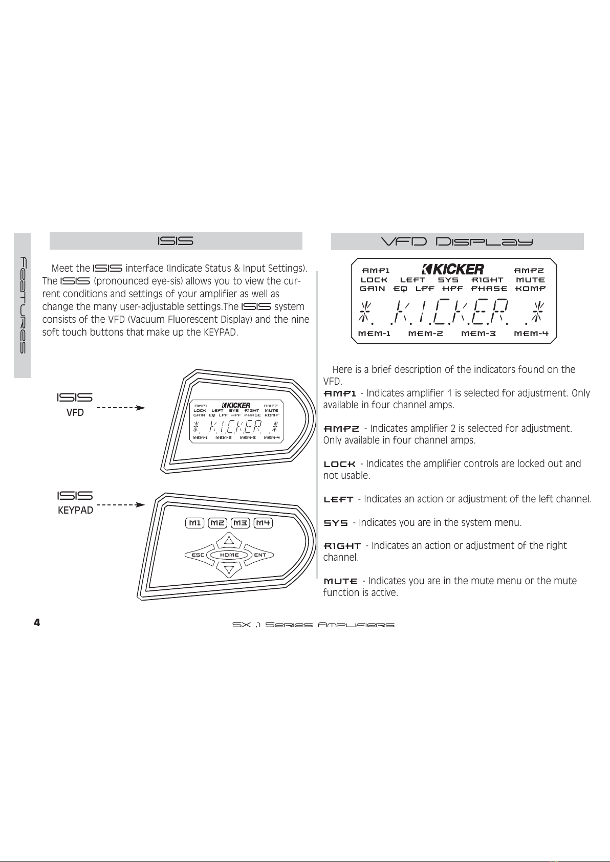
Meet the ISIS interface (Indicate Status & Input Settings).
The ISIS (pronounced e e-sis) allows ou to view the cur-
rent conditions and settings of our amplifier as well as
change the man user-adjustable settings.The ISIS s stem
consists of the VFD (Vacuum Fluorescent Displa ) and the nine
soft touch buttons that make up the KEYPAD.
M1 M2 M3 M4
ESC ENT
HOME
SYS
MEM-1
GAIN EQ LPF HPF KOMP
AMP1
LOCK
MEM-2 MEM-3 MEM-4
PHASE
MUTE
AMP2
LEFT RIGHT
** kicker
ISIS
VFD
ISIS
KEYPAD
Here is a brief description of the indicators found on the
VFD.
$03- Indicates amplifier 1 is selected for adjustment. Onl
available in four channel amps.
$03- Indicates amplifier 2 is selected for adjustment.
Onl available in four channel amps.
/2&.- Indicates the amplifier controls are locked out and
not usable.
/()7- Indicates an action or adjustment of the left channel.
6<6- Indicates ou are in the s stem menu.
5,*+7- Indicates an action or adjustment of the right
channel.
087(- Indicates ou are in the mute menu or the mute
function is active.
All manuals and user guides at all-guides.com

5
SX .1 Series Amplifiers
Features
VFD DISPLAY - cont
*$,1 - Indicates ou are in the gain menu.
(4 - Indicates ou are in the equalizer menu.
/3) - Indicates ou are in the low pass filter menu.
+3) - Indicates ou are in the high pass filter menu.
3+$6( - Indicates ou are in the phase menu.
.203 - Indicates ou are in the Kompressor menu.
0(0 - Memor preset 1 activated.
0(0 - Memor preset 1 activated.
0(0 - Memor preset 1 activated.
0(0 - Memor preset 1 activated.
KEYPAD
The ke pad consists of nine buttons that allow ou to adjust
our amplifier.
0- Used to select memor preset 1 or to store cur-
rent settings into preset 1.
0- Used to select memor preset 2 or to store
current settings into preset 2.
0- Used to select memor preset 3 or to store
current settings into preset 3.
0- Used to select memor preset 4 or to store
current settings into preset 4.
(6&- Used to exit the current menu.
(17- Used to enter the selected menu.
+20(- Used to return to the Main menu and
other functions explained later.
83- Used to advance up through menu selections
and/or adjust amplifier controls.
'2:1- Used to advance down through menu
selections and/or adjust amplifier controls.
These controls and their usage will be explained later with
more detail in each menu usage section.
ESC
M2
M3
M4
ENT
HOME
M1
All manuals and user guides at all-guides.com
6SX .1 Series Amplifiers
Features
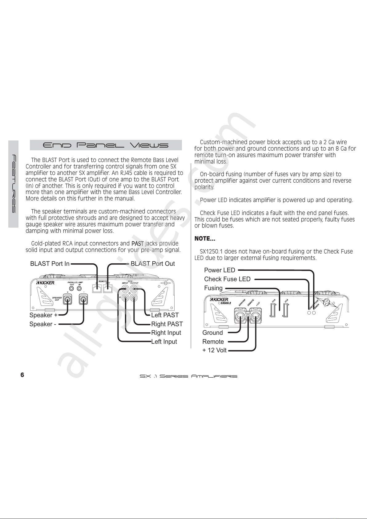
End Panel Views
The BLAST Port is used to connect the Remote Bass Level
Controller and for transferring control signals from one SX
amplifier to another SX amplifier. An RJ45 cable is required to
connect the BLAST Port (Out) of one amp to the BLAST Port
(In) of another. This is onl required if ou want to control
more than one amplifier with the same Bass Level Controller.
More details on this further in the manual.
The speaker terminals are custom-machined connectors
with full protective shrouds and are designed to accept heav
gauge speaker wire assures maximum power transfer and
damping with minimal power loss.
Gold-plated RCA input connectors and PAST jacks provide
solid input and output connections for our pre-amp signal.
Speaker +
Speaker -
Left Input
Left PAST
Right Input
Right PAS
T
BLAST Port In BLAST Port Out
XX
XX
Ground
Remote
+ 12 Vo t
Fusing
Power LED
Check Fuse LED
Custom-machined power block accepts up to a 2 Ga wire
for both power and ground connections and up to an 8 Ga for
remote turn-on assures maximum power transfer with
minimal loss.
On-board fusing (number of fuses var b amp size) to
protect amplifier against over current conditions and reverse
polarit .
Power LED indicates amplifier is powered up and operating.
Check Fuse LED indicates a fault with the end panel fuses.
This could be fuses which are not seated properl , fault fuses
or blown fuses.
NOTE...
SX1250.1 does not have on-board fusing or the Check Fuse
LED due to larger external fusing requirements.
All manuals and user guides at all-guides.com
all-guides.com
7
SX .1 Series Amplifiers
Installation
ounting
When selecting a location to mount our Kicker amplifier be
sure it is structurall sound and that there are no items
behind the area that could be damaged b the screws. Check
for wiring, brake lines, fuel lines, gas tanks, etc.
All amplifiers generate heat under normal operation. Be sure
to choose a location that allows adequate ventilation for the
amplifier. Also consider that the air temperature inside an
automobile’s trunk can reach upwards of 140 degrees fahren-
heit. An amplifier mounted in the trunk ma require additional
cooling such as extra fans moving air around the amplifier’s
chassis or ventilating the trunk to exchange the hot air in the
trunk for cooler air outside. If possible, mounting the amp in
the passenger compartment will allow cooler operation.
Remember that the controls on top of the amp will need to
be accessible for adjustment later. Keep this in mind as ou
choose our amplifier’s mounting location.
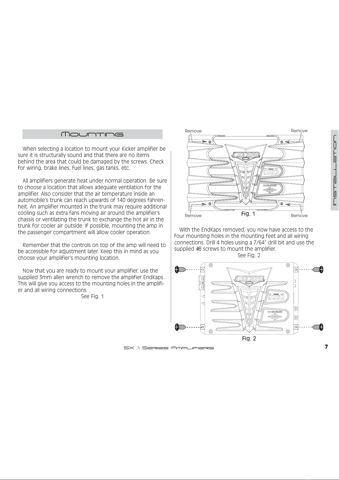
Now that ou are read to mount our amplifier, use the
supplied 3mm allen wrench to remove the amplifier EndKaps.
This will give ou access to the mounting holes in the amplifi-
er and all wiring connections.
See Fig. 1
Remove Remov
e
Remove Remov
e
M1 M2 M3 M4
ESC ENT
HOME
R
SYS
MEM-1
GAIN EQ LPF HPF KOMP
AMP1
LOCK
MEM-2 MEM-3 MEM-4
PHASE
MUTE
AMP2
LEFT RIGHT
** kicker
With the EndKaps removed, ou now have access to the
four mounting holes in the mounting feet and all wiring
connections. Drill 4 holes using a 7/64” drill bit and use the
supplied #8 screws to mount the amplifier.
See Fig. 2
R
M1 M2 M3 M4
ESC ENT
HOME
SYS
MEM-1
GAIN EQ LPF HPF KOMP
AMP1
LOCK
MEM-2 MEM-3 MEM-4
PHASE
MUTE
AMP2
LEFT RIGHT
** kicker
Fig. 1
Fig. 2
All manuals and user guides at all-guides.com

8SX .1 Series Amplifiers
Installation
Wiring
Signal is input into the amplifier using the low level RCA
input connections. If our source unit does not have RCA
output connectors ou will need to use a Hi-Lo level signal
adapter. See our Kicker dealer for more details on this.
The output (PAST) RCA jacks provide an unaltered signal
output to feed another amplifier or component.
SOURCE UNIT
The use of twisted pair interconnects is recommended for
all installations to minimize noise. When routing these cables
through the automobile, tr to keep them awa from factor
wiring harnesses and other power wiring. If ou need to cross
an of this wiring do so at a 90 degree angle to reduce the
possibilit for noise problems.
When working with power connections it is alwa s recom-
mended that ou disconnect the batter to prevent accidents.
The ground should be connected to the amplifier first
before making an of the other connections. This wire should
be as short as possible (24 inches or less) and connected to a
paint/corrosion free solid metal area of the car’s chassis. Use
the same gauge wire as recommended for the amplifier’s
power connection to the batter . Adding an additional ground
wire between the car batter ’s negative post and the car chas-
sis of this same gauge (or larger) is also recommended.
If ou ever need to remove the amp from the vehicle after
it has been installed, the ground wire should be the last wire
disconnected from the amplifier, just the opposite of when
ou installed it.
A fuse must be installed within 18 inches of the batter to
protect the power wire feeding our amplifier. This fuse
should be of at least the same value used in the amplifier but
no higher than the capacit of the power wire. See the charts
below for wire size and fusing recommendations.
Model Fuse Size Wire Size
Wire Size Length Ma imum Fuse
SX650.1
SX1250.1
60A
150A
4 GA
2 GA
8 Ga
4Ga
2 Ga
0Ga
8 Ga
4 Ga
2 Ga
0 Ga
Less than
10 feet in
length
70 Amps
175 Amps
250 Amps
400 Amps
40 Amps
90 Amps
150 Amps
200 Amps
10 feet to
20 feet in
length
All manuals and user guides at all-guides.com
9
SX .1 Series Amplifiers
Installation
System Diagrams
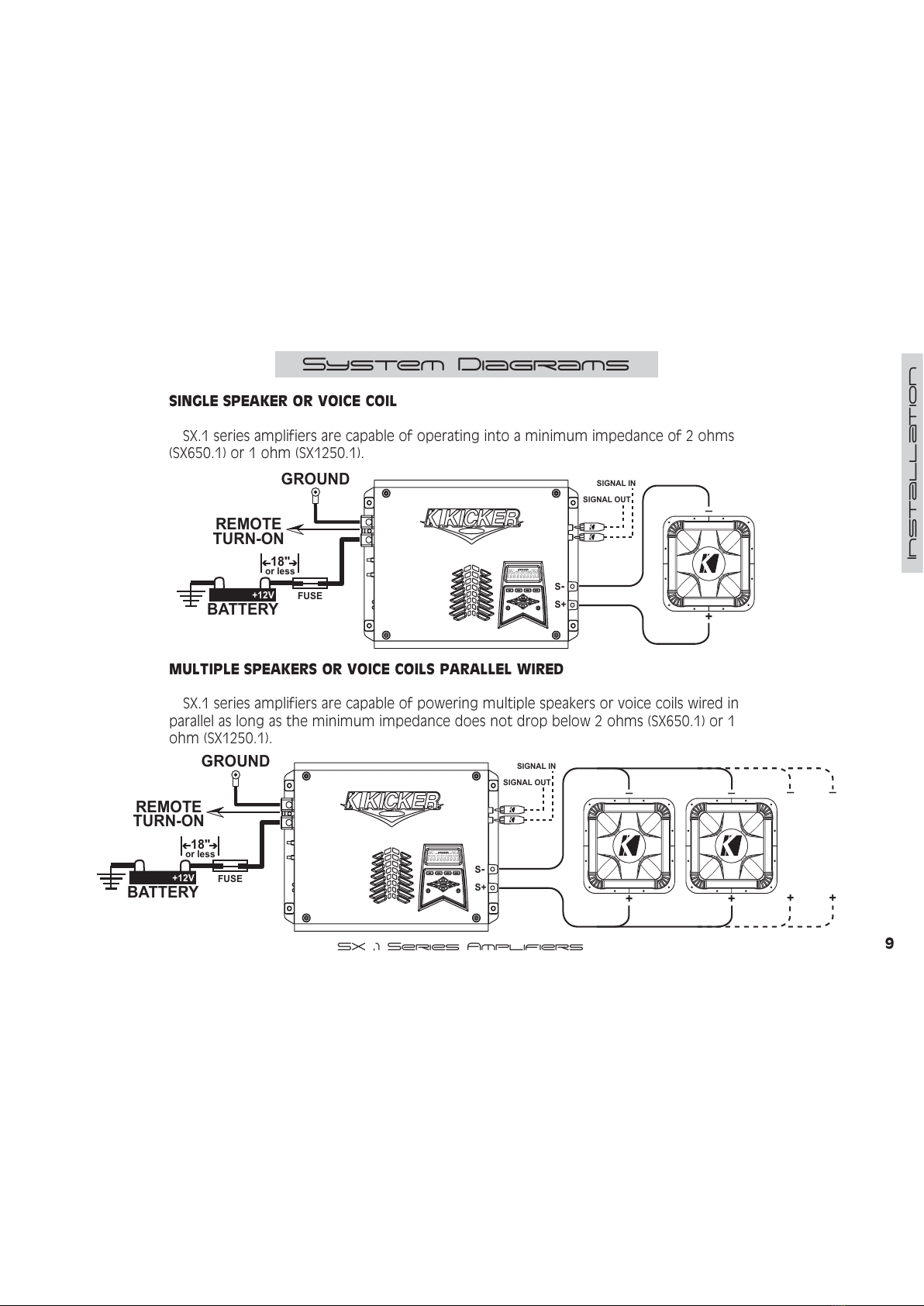
SINGLE SPEAKER OR VOICE COIL
SX.1 series amplifiers are capable of operating into a minimum impedance of 2 ohms
(SX650.1) or 1 ohm (SX1250.1).
+
_
GROUND
REMOTE
TURN-ON
BATTERY
+12V FUSE
18"
or less
S+
S-
ESC HOME ENT
M1
AMP 1
LOCK LEFT SYS RIGHT MUTE
AMP 2
GAINEQ LPF HPF PHASE KOMP
8888888888.........
M2 M3 M4
SIGNAL OUT
SIGNAL IN
MULTIPLE SPEAKERS OR VOICE COILS PARALLEL WIRED
SX.1 series amplifiers are capable of powering multiple speakers or voice coils wired in
parallel as long as the minimum impedance does not drop below 2 ohms (SX650.1) or 1
ohm (SX1250.1).
GROUND
REMOTE
TURN-ON
BATTERY
+12V FUSE
18"
or less
S+
S-
ESC HOME ENT
M1
AMP 1
LOCK LEFT SYS RIGHT MUTE
AMP 2
GAINEQ LPF HPF PHASE KOMP
8888888888.........
M2 M3 M4
SIGNAL OUT
SIGNAL IN
+
_
+
_
+
_
+
_
All manuals and user guides at all-guides.com

10 SX .1 Series Amplifiers
Installation
MULTIPLE SPEAKERS OR VOICE COILS SERIES WIRED
SX.1 series amplifiers are capable of powering multiple speakers or voice coils wired in
series as long as the minimum impedance does not drop below 2 ohms (SX650.1) or 1 ohm
(SX1250.1).
GROUND
REMOTE
TURN-ON
BATTERY
+12V FUSE
18"
or less
S+
S-
ESC HOME ENT
M1
AMP 1
LOCK LEFT SYS RIGHT MUTE
AMP 2
GAINEQ LPF HPF PHASE KOMP
8888888888.........
M2 M3 M4
SIGNAL OUT
SIGNAL IN
+
_
+
_
+
_
These are just a few of the man wa s ou can use our SX.1 series Kicker amplifier.
These s stem diagrams are designed to give ou a basic understanding of the most com-
mon uses for this amplifier. For more complex s stems please visit our local authorized
Kicker dealer. You can also download the SX Technical Manual from our website at
www.kicker.com for more detailed information and complex s stem diagrams.
All manuals and user guides at all-guides.com

11
SX .1 Series Amplifiers
Installation
AMPLIFIER STRAPPING
SX.1 series amplifiers are capable of being strapped
together to provide twice the power into twice their rated
minimum impedance. Onl like model amps can be strapped
together. In other words, the SX650.1 can onl be strapped to
another SX650.1 and the SX1250.1 can onl be strapped to
another SX1250.1.
NOTE...
4 ohm minimum impedance for SX650.1 when strapped.
2 ohm minimum impedance for SX1250.1 when strapped.
1.) Wire both amplifiers to 12 volt power, ground and
remote.
2.) Connect a RCA cable from the source unit to the RCA
Input jacks on the primar amp.
3.) Use the supplied 1/8 inch mono cable to connect the
Amp Strapping Out jack of the primar amplifier to the
Amp Strapping In jack of the secondar amplifier.
4.) Use a short piece of heav gauge wire (12Ga, 10Ga, 8Ga)
to connect the Speaker negative terminals of both amps
together.
5.) The primar amplifier’s positive terminal is used for the
positive speaker connections.
6.) The secondar amplifier’s positive terminal is used for the
negative speaker connections.
AMP STRAPPING
AMP STRAPPING
SOURCE UNIT
+
_
All manuals and user guides at all-guides.com
all-guides.com

12 SX .1 Series Amplifiers
Installation
AMPLIFIER STRAPPING WITH REMOTE BASS CONTROL
The Remote Bass Level Controller can be used to adjust the
output level of both the amplifiers that are strapped together.
1.) Mount the Remote Bass Level Controller in the front of
our vehicle and plug in the supplied cable.
2.) Route the supplied cable to the primar amplifier and
connect to its BLAST In jack.
3.) Enjo !
BACK VIEW
SIDE VIEW
Mounting Surface
SUPPLIED
CABLE
AMP STRAPPING
AMP STRAPPING
SOURCE UNIT
+
_
All manuals and user guides at all-guides.com

13
SX .1 Series Amplifiers
Installation
USING THE SIGNAL OUTPUT JACKS (PAST)
The Output (Pre Amp Signal Transfer) RCA jacks allow ou to
send the incoming signal from one Kicker SX series amplifier
to another amplifier or processor without the need for Y
cables. The signal from the PAST jacks is identical to the signal
fed to the amplifier via its RCA input jacks and is not affected
b an of the amplifier’s built-in digital signal processing.
Most head units with high voltage outputs should be capa-
ble of driving up to ten amplifiers in a chain.
SOURCE UNIT
AMP STRAPPING
AMP STRAPPING
To Ne t Amplifier or Processor
All manuals and user guides at all-guides.com
14 SX .1 Series Amplifiers
INSTALLATION
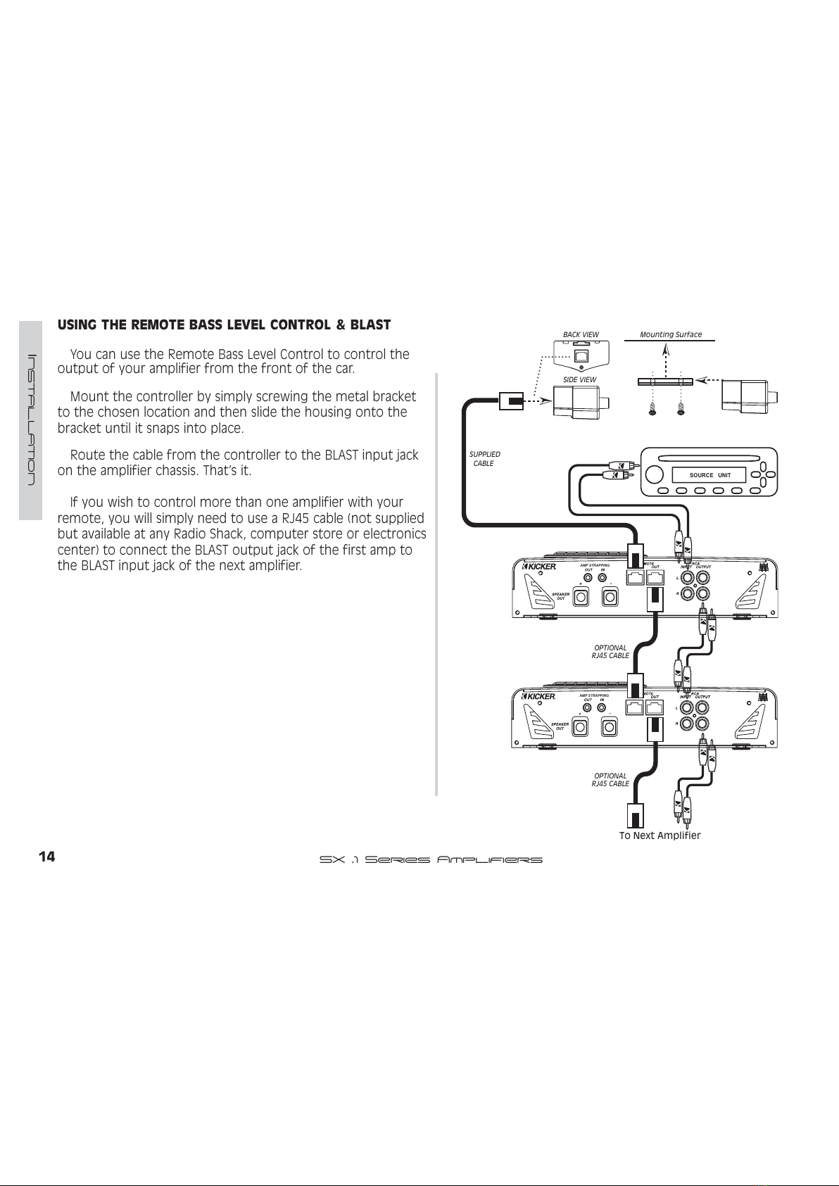
USING THE REMOTE BASS LEVEL CONTROL & BLAST
You can use the Remote Bass Level Control to control the
output of our amplifier from the front of the car.
Mount the controller b simpl screwing the metal bracket
to the chosen location and then slide the housing onto the
bracket until it snaps into place.
Route the cable from the controller to the BLAST input jack
on the amplifier chassis. That’s it.
If ou wish to control more than one amplifier with our
remote, ou will simpl need to use a RJ45 cable (not supplied
but available at an Radio Shack, computer store or electronics
center) to connect the BLAST output jack of the first amp to
the BLAST input jack of the next amplifier.
SOURCE UNIT
To Ne t Amplifier
AMP STRAPPING
AMP STRAPPING
BACK VIEW
SIDE VIEW
Mounting Surface
SUPPLIED
CABLE
OPTIONAL
RJ 5 CABLE
OPTIONAL
RJ 5 CABLE
All manuals and user guides at all-guides.com

15
SX .1 Series Amplifiers
Operation
Navigation
Your KICKER SX series amplifier uses the latest in Digital DSP
control and provides ou with valuable operational informa-
tion about our amplifier, real-time diagnostics and a full
multi-level menu-driven operating s stem to access and
adjust our amplifier.
The menu s stem is designed in la ers. There is a starting
point and ou keep drilling down until ou get to the menu
item ou want to view or change. This menu tree is an
example of how the SX menu structure is set up.
NOTE Not all the menus and menu items are shown below.
DEFAULT
SCREEN
SYSTEM
GAIN
EQ
LO-PASS
HI-PASS
CURRENT
HISTORY
∝
...
∝
...
∝
*MAIN MENU
SYSTEM MENU
SICK BAY MENU
VOLT NOW
VOLT MIN
VOLT MAX
TEMP NOW
TEMP MAX
∝
...
RUN TIME
SICK BAY
As ou can see there can be an infinite number of menu
levels and each one of these menu levels can have an infinite
number of its own items.
Navigating this simple menu
structure is ver eas using the 5-wa
ke pad.
You use the 83 and '2:1 ke s to scroll through the
available menu items, and the (17 ke is used to select that
menu item. The (6& ke backs ou up one menu level from
where ou are, and the +20( ke can return ou all the
wa to MAIN MENU b pressing and holding it for 1.5 seconds.
For example let’s begin at the DEFAULT SCREEN; our goal is
to get to the HISTORY menu. Pressing the (17 ke would get
us to MAIN MENU. Now use the 83 and
'2:1 ke s to scroll to SYSTEM, and
then press the (17 ke . Now ou are
in the SYSTEM MENU. Using the 83 and
'2:1 ke s again ou scroll to SICK
BAY and press the (17 ke . You are
now in the SICK
BAY MENU. Use the 83 and '2:1
ke s again to scroll to HISTORY and then
press the (17 ke . That’s it! You are
there.
This is how ou view information
and change settings in our KICKER SX amplifier.
HOME ENT
ESC
HOME ENT
ESC
HOME ENT
ESC
All manuals and user guides at all-guides.com

16 SX .1 Series Amplifiers
Operation
Continuing our example, we are now in the HISTORY item in
the SICK BAY MENU. If we press the
(6& ke we would go back up to the
SICK BAY MENU. If we press the (6&
ke again we would go to the SYSTEM
MENU. One more press of the (6&
ke and we are in the MAIN MENU.
Let’s start at the HISTORY item in the SICK BAY MENU again
but instead press and hold the +20( ke for 1.5
seconds. Doing this will take us all the wa back to the MAIN
MENU in one ke press. Pressing and
holding the +20( ke will return ou
all the wa back to the MENU ITEM ou
started with in the MAIN MENU, no mat-
ter how deep in the menu level struc-
ture ou are. Prett cool!
This is a ver quick wa to return to the MAIN MENU after
drilling down several menu la ers to view or change an item.
When adjusting an amplifier control the 83 and '2:1
arrow ke s have 2 speeds, normal and accelerated.
Pressing and releasing the ke
repeatedl will scroll through the menu
items at normal speed.
Pressing the ke and holding it in for
longer than 1.5 seconds will activate the
accelerated scrolling mode and scroll
through the menu items at a much
faster rate. Releasing the ke will return
it to normal speed mode.
Don’t tr to scroll through ever 1/12 octave step without
it!
HOME ENT
ESC
HOME ENT
ESC
HOME ENT
ESC
PRESS &
RELEASE
HOME ENT
ESC
PRESS &
HOLD
PRESS &
HOLD
All manuals and user guides at all-guides.com
all-guides.com

17
SX .1 Series Amplifiers
Operation
enu System
The menu s stem la out is as follows:
DEFAULT - This menu is displa ed when our amp is
operating and no adjustments are being made to our ampli-
fier. This information scrolls through the displa one after the
other and then repeats.
1.) KICKER - He , we needed a brand plug for us since this
amp is
sooooo
cool!
2.) XX.X Volts - Displa s the current voltage at the
amplifier’s + 12 volt batter input terminal.
3.) XX.X DEG f or xx.x DEG c - Displa s the current
temperature of the amplifier in celsius or fahrenheit.
4.) amp name - Model name of the amplifier or the name
ou have changed it to.
5.) memory name - Current memor preset in use (if
an ) or the name ou have changed it to.
If ou want to freeze the scrolling
displa simpl press the +20( ke
and the scrolling will stop.
Now ou can manuall select the item
ou wish to have displa ed b using the
83 or '2:1 ke s.
If ou want the displa to continue scrolling simpl press
the +20( ke again.
MAIN - This menu is the first menu accessed from the
DEFAULT menu and is the gatewa to all the settings and
information on our SX series amplifier.
To enter the MAIN menu simpl press
the (17 ke while in the DEFAULT
menu.
The available selections in the MAIN menu are:
System
GAIN
EQ
Lo- ass
Hi- ass
hase
Mute
Kompressor
Security
Use the 83 and '2:1 arrow ke s
to scroll through the available selections
in the MAIN menu.
When ou have the menu item
selected that ou want to view or adjust
simpl press the (17 ke to select it.
HOME ENT
ESC
HOME ENT
ESC
HOME ENT
ESC
HOME ENT
ESC
HOME ENT
ESC
All manuals and user guides at all-guides.com

18 SX .1 Series Amplifiers
Operation
SYSTEM MENU - This menu item contains man diagnostic
tools and first time setup options. Use the 83 and '2:1
arrow ke s to scroll through the options and press (17 to
select. Press the (6& ke to return to the SYSTEM menu.
1.) Volt Now - Displa s the current voltage at the
amplifiers +12 volt terminal.
2.) Volt Min - Displa s the lowest voltage seen at the
amplifiers +12 volt terminal since being installed.
3.) Volt Max - Displa s the highest voltage at the
amplifiers +12 volt terminal since being installed.
4.) Temp Now - Displa s the current temperature of
the amplifier.
5.) Temp Max - Displa s the highest temperature the
amplifier has reached since being installed.
6.) Run Time - Displa s the total time the amplifier
has been powered up since installation in 1/10th of
an hour increments
7.) Sick Bay - Contains several
diagnostic tools. Once in this menu
ou use the 83 and '2:1 ke s to
scroll through CURRENT,HISTORY and
INK NOISE options. Press the (17
ke to select.
7a.) CURRENT shows amplifiers current status or fault
code. The 6 possible codes are:
normal - No problem, normal operation.
thermal - Thermal cutoff protection engaged.
short - Short circuit protection engaged.
Hi-Volt - High voltage protection engaged.
FUSE - Faulty or blown power fuse.
SERVICE - Amp requires service by KICKER.
When ou are done viewing
the current status press the
(6& ke to return to the SICK
BAY menu.
7b. )HISTORY logs the last 5 fault codes and how
long ago the happened when
compared to the RUN TIME log.
Use the 83 and '2:1
ke s to select the HISTORY log
entr ou want to view.
Press and hold the (17 ke
to view the time it happened.
When ou are done viewing
the histor press the (6& ke .
HOME ENT
ESC
HOME ENT
ESC
HOME ENT
ESC
HOME ENT
ESC
HOME ENT
ESC
All manuals and user guides at all-guides.com

19
SX .1 Series Amplifiers
Operation
SICK BAY - cont
7c.) INK NOISE is a built in pink noise generator
to test operation of the amplifier
Use the 83 and '2:1
ke s to select NOISE ON or
NOISE OFf.
When the PINK NOISE is ON
the LEFT and RIGHT indicators
in the ISIS VFD will blink on
and off.
When ou are done using the
PINK NOISE generator press the
(6& ke to return to the SICK
BAY menu.
NOTE...
If ou exit the SICK BAY menu with the PINK NOISE generator
still on, the LEFT and RIGHT ISIS VFD indicators will remain
blinking as a reminder.
HOME ENT
ESC
SYS
MEM-1
GAIN EQ LPF HPF KOMP
AMP1
LOCK
MEM-2 MEM-3 MEM-4
PHASE
MUTE
AMP2
LEFT RIGHT
noise on
HOME ENT
ESC
8.) Amp Name - Here ou can assign a unique name to
our KICKER SX amplifier. This name will replace the model
name in the DEFAULT screen. If ou change our mind and
do not want to change the name, press and hold the
+20( ke for 1.5 seconds BEFORE making an changes.
The (6& and (17 ke s move
the cursor left or right to select
which character to change.
Use the 83 and '2:1 ke s to
change the character displa ed
(A, B, C...1, 2, 3...etc)
When ou are finished press and
hold the +20( ke for 1.5
seconds to save our new
amplifier name.
HOME ENT
ESC
HOME ENT
ESC
HOME ENT
ESC
PRESS &
HOLD
All manuals and user guides at all-guides.com
20 SX .1 Series Amplifiers
Operation
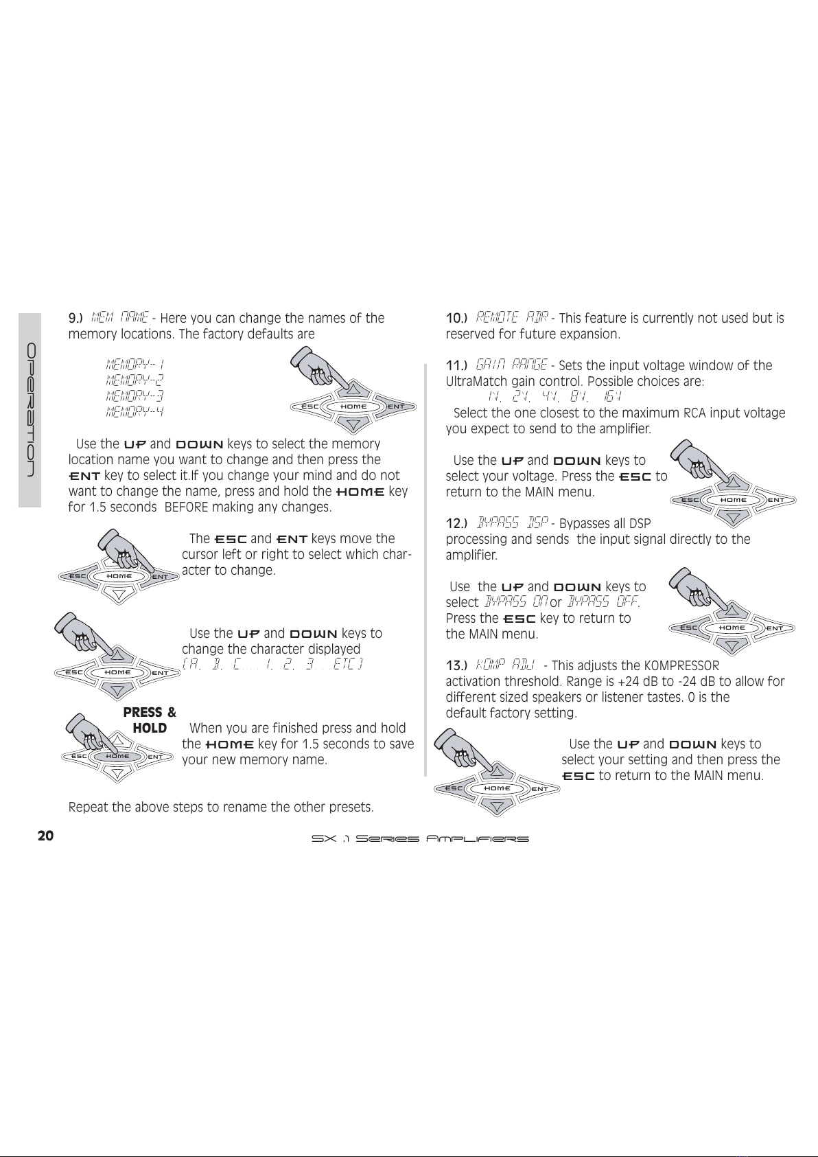
9.) Mem Name - Here ou can change the names of the
memor locations. The factor defaults are
Memory-1
Memory-2
Memory-3
Memory-4
Use the 83 and '2:1 ke s to select the memor
location name ou want to change and then press the
(17 ke to select it.If ou change our mind and do not
want to change the name, press and hold the +20( ke
for 1.5 seconds BEFORE making an changes.
The (6& and (17 ke s move the
cursor left or right to select which char-
acter to change.
Use the 83 and '2:1 ke s to
change the character displa ed
(A, B, C...1, 2, 3...etc)
When ou are finished press and hold
the +20( ke for 1.5 seconds to save
our new memor name.
Repeat the above steps to rename the other presets.
10.) Remote Adr - This feature is currentl not used but is
reserved for future expansion.
11.) Gain Range - Sets the input voltage window of the
UltraMatch gain control. Possible choices are:
1V, 2V, 4V, 8V, 16V
Select the one closest to the maximum RCA input voltage
ou expect to send to the amplifier.
Use the 83 and '2:1 ke s to
select our voltage. Press the (6& to
return to the MAIN menu.
12.) Bypass DS - B passes all DSP
processing and sends the input signal directl to the
amplifier.
Use the 83 and '2:1 ke s to
select BY ASS ON or BY ASS OFF.
Press the (6& ke to return to
the MAIN menu.
13.) Komp Adj. - This adjusts the KOMPRESSOR
activation threshold. Range is +24 dB to -24 dB to allow for
different sized speakers or listener tastes. 0 is the
default factor setting.
Use the 83 and '2:1 ke s to
select our setting and then press the
(6& to return to the MAIN menu.
HOME ENT
ESC
HOME ENT
ESC
HOME ENT
ESC
HOME ENT
ESC
HOME ENT
ESC
HOME ENT
ESC
PRESS &
HOLD
HOME ENT
ESC
All manuals and user guides at all-guides.com
This manual suits for next models
3
Table of contents
Other Stillwater Designs Amplifier manuals


