Stillwater Designs KICKER VSS PWRA407 User manual

©2012 Stillwater Designs
PWRA407-A2-20140731
Page 1 of 9
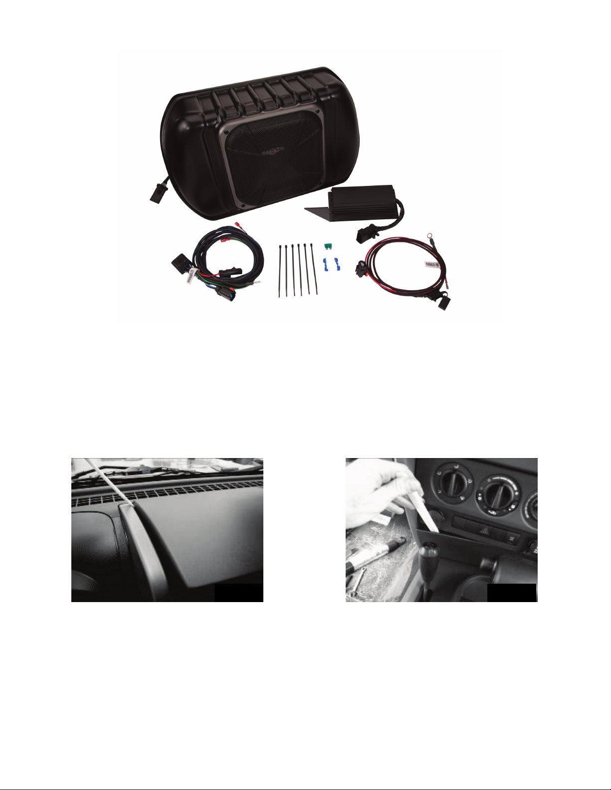
PWRA407
Designed for 2007-2010 Jeep® Wrangler four door with base audio
BRACKET ASSEMBLY
M6 BOLT
FUSE
AMP SCREWS x4
AMP WASHERS x4
WIRE TIES x6
5-CHANNEL AMP
OVERLAY HARNESS
POWER HARNESS
Page 2 of 9
Fig. 1
Fig. 2
Radio Removal
1. Disconnect the negative battery terminal before you begin.
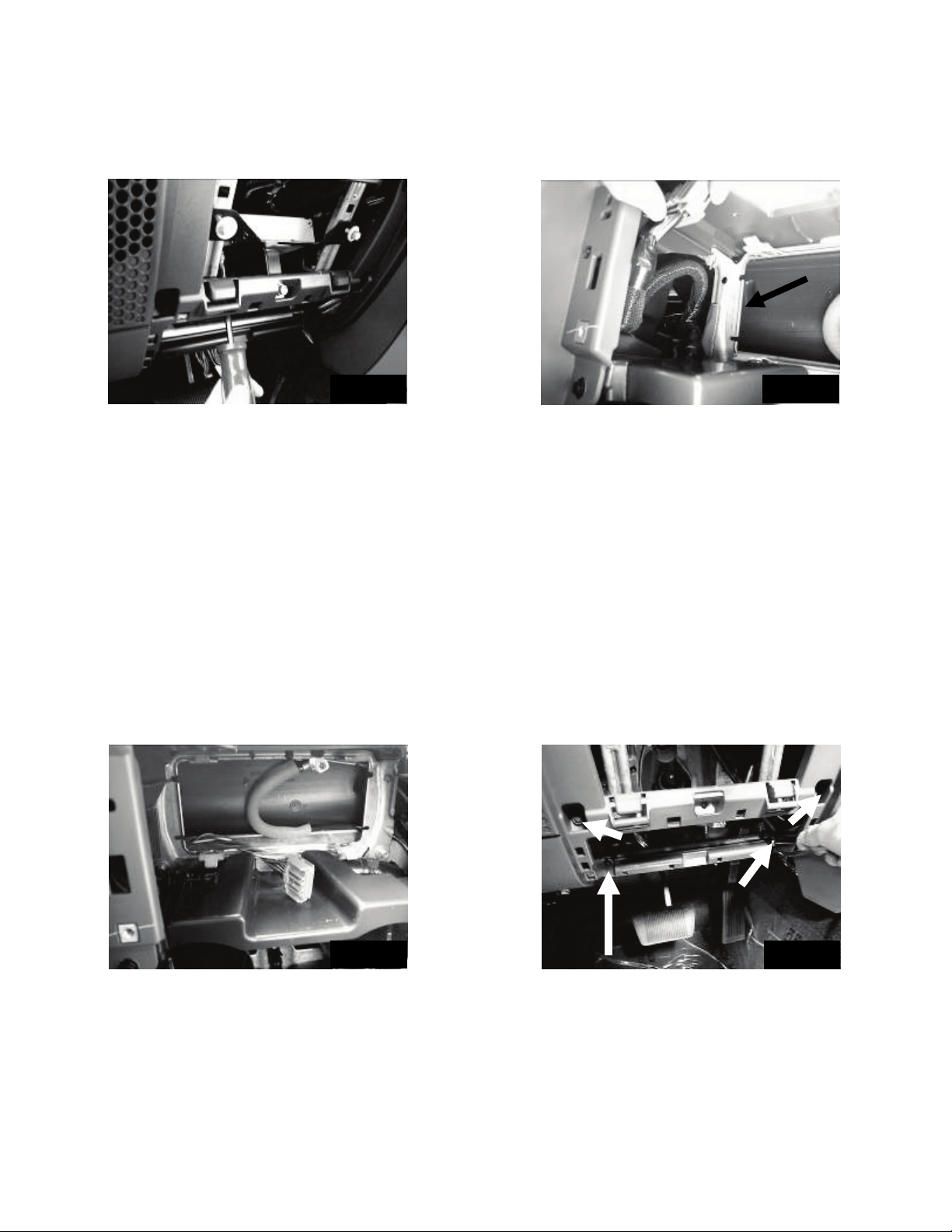
2. Using a panel removal tool, pry up on the plastic trim panel located above the radio. Make sure to pry
on the side of the panel closest to the window. Fig. 1
3. Using a panel removal tool pry loose the top edge of the panel below the HVAC controls. Fig. 2
4. Remove the four screws securing the radio trim bezel. There are two at the top and two at the bottom.
Fig. 3
5. Starting at the top and working your way down pull out on the trim bezel to release the fasteners
securing it. Once the bezel is completely detached from the dash it is not necessary to disconnect
any of the wiring or the HVAC linkage. Simply allow the bezel to rest on the console to allow access to
the screws securing the radio. Fig. 4
T-TAP x2
FUSE
WIRE TIES x6
SUBWOOFER ASSEMBLY
200 WATT AMP
POWER HARNESS
OVERLAY HARNESS

Page 3 of 9
Fig. 5
Fig. 6
Fig. 3 Fig. 4
Fig. 7 Fig. 8
6. Remove the screws securing the radio and pull the radio from the dash and disconnect the wiring.
Disconnect the antenna cable by pulling the locking antenna connector away from the radio. Caution:
Pulling the antenna cable straight out of the radio without pulling on the locking antenna connector
could damage the cable or radio.
Amp Installation
7. Gently pull out on the panel just below the steering column, rotate down and remove. Fig. 5
8. Find the small panel just below the one you just removed and pull to remove it as well. Fig. 6
9. Remove the two bolts securing the metal plate below the steering column. Fig. 7
10.Install the amp bracket in between the dash frame rails and line up the holes in the bracket with the
holes. Install the supplied 10mm bolt in the lower middle hole but do not tighten.
11.Temporarily install the two bolts that retain the metal plate in order to stabilize the amp bracket while
the amp is mounted. Fig. 8
Page 4 of 9
Fig. 9
A
Fig. 12
12.Place the amp on top of the bracket by sliding it under the dash past the brake pedal. Make sure the
connecters on the amp are facing toward the fire wall and the mounting holes are facing down.
13.Using a Torx® T-25 screwdriver install the four supplied screws and washers to attach the amp to the
amp bracket. Fig. 9
14.Pass the factory radio harness connecter behind the metal framework indicated by the arrow. Fig. 10
15.Connect the amplifier harness to the amplifier and route the harness up to the radio cavity.
16.Connect the male radio harness connecter to the female connecter of the amp harness and tuck this
connection into the void between the radio opening and the instrument cluster to avoid interference
with radio during reinstallation.
17.Route male connector of the amp harness back around the beam as the radio harness originally was.
Fig. 11
18.You can now connect the radio to the amplifier harness and reconnect the antennae wire and reinstall
the radio.
19.Remove the two 10mm bolts temporarily installed in step 10. Position the metal plate removed
previously over the top of the amp bracket and secure both with the two 10mm bolts.
20.Tighten the bottom bolt.
21.Loosen the four screws indicated by the arrows in Fig. 12 approximately 4 turns.
22.Remove the screw indicated by arrow A completely. Fig. 12
23.Install the amplifier with the long tab toward the center of the car. Slide the long tab behind the plastic
and under the lower right screw while pulling out on the plastic. Once tab is completely seated rotate
the amplifier down and secure the short tab in the same manner. Reinstall screw A and retighten the
screws but leave the covers uninstalled. Fig. 13
Fig. 10
Fig. 11

Page 5 of 9
Fig. 14
Fig. 15
Fig. 16
Fig. 17
Power Harness Installation
24.Find the rubber grommet in the top driver’s side of the fire wall underneath the hood and remove it. Fig.
14
25.Using a razor knife make a small cut in the center of the grommet. Pass the end of the wires with the
small terminal on the ends through the grommet and pull the grommet up to the point where the plastic
sheathing starts. Fig. 15
26.Run the wires through the grommet hole in the fire wall and reinstall the grommet.
27.Run the wires along the top of the fire wall toward the battery and secure with wire ties.
28.Remove the top of the fuse cover and using a 13mm socket and ratchet loosen and remove the nut
on the positive battery accessory lug. Fig. 16
29.Connect the ring terminals of the power harnesses to the lug and retighten the nut. Torque to 10Nm.
30.Using a panel removal tool remove the four plastic retainers (three in front door opening and one in rear
door opening) securing the driver’s side sill plate and B pillar post cover. Fig. 17
Fig. 13

Page 6 of 9
Fig. 20
Fig. 18
Fig. 21
Fig. 19
31.Gently pull the kick panel/sill plate toward the brake pedal to release the fasteners securing it.
32.Connect the ten pin connector of the harness to the amplifier. Slide the red locking tab over to prevent
the connector from accidentally coming disconnected.
33.Route the harness along the bottom of the front and rear door jam and toward the back seat.
34.Connect the two pin connector of the amplifier harness to the two pin connector of the subwoofer
harness.
35.Install the supplied white, three-pin connector by inserting the terminals on the end of the power wire
into the back of the connector until they click and lock. Any wire can go in any hole. Fig. 18
36.Install the supplied black, two-pin connector by inserting the terminals on the end of the power wire
into the back of the connector until it clicks and locks. Fig. 19
37.Depress the blue terminal retainer down in the center of the connector.
38.Remove one of the factory ground nuts on the driver’s side kick area. Connect the two black ground
wires, reinstall the nut and tighten. Fig. 20. Torque to 8Nm.
39.Connect the green wire of the amplifier harness to the green wire of the subwoofer harness. Then,
connect the brown wire of the amplifier harness to the brown wire of the subwoofer harness. Fig. 21
40.Run the wire harness along the floor under the rear seats to approximately the middle of the vehicle
and pull the end of the harness under the seat to the cargo area.
41.Set the subwoofer in place and connect the wire harness.
42.Rotate the rear seat back until it is nearly vertical. While holding the seat back with one hand, slide the
enclosure back until the hooks on the bracket are centered under the anchor points at the bottom of
the seat. Slowly rotate the seat back toward the rear of the vehicle until it locks into place. Fig. 22

Page 7 of 9
Fig. 22
43.Reinstall all previously removed parts in reverse order.
44.Reinstall supplied fuses in the fuse holders under hood.
45.Reconnect the negative battery cable. Torque to 5Nm.
Troubleshooting the Kicker Integrated Systems
If you experience a problem once the Subwoofer is installed use this guide to locate the trouble.
The radio is working, but the Subwoofer is not working:
•Check the battery voltage to make sure it is not discharged below 11 volts.
•Check the negative battery cable to see if it has been securely tightened back on the battery.
•Check the inline fuse located near the battery to make sure it is plugged in completely, and not blown.
•Check the inline +12Volt power-connector near the firewall to make sure it is plugged in securely.
•Check the inline connectors near the subwoofer enclosure to make sure they are plugged securely.
•Check the ground wire connection to make sure it is tightly secured to the proper ground in the
vehicle.
•Check the audio input signal connection to make sure it is secure and connected to the proper wiring.
•Test with different music in case there is no low frequency audio in the initial sound check.
There is a buzz or rattle noise that accompanies the
low frequency element of the music:
•Check for a connector or any other object that could be very near the subwoofer or the enclosure.
•Check the subwoofer enclosure mounting brackets to make sure they are secure.
There is a problem with the multi-channel stereo amplifier:
•Check the battery voltage to make sure it is not discharged below 11 volts.
•Check the negative battery cable to see if it has been securely tightened back on the battery.
•Check the inline fuse located near the battery to see if it is plugged in completely and not blown.
•Check the multi-pin connectors at the back of the radio and at the amplifier chassis to make sure they
are plugged all the way in.
•Check the ground wire connection to make sure it is tightly secured to the proper ground in the
vehicle.

Page 8 of 9
Symptom
Possible Cause
Solution
No Subwoofer Output
Fuse not installed in inline
fuse holder on subwoofer
and/or amp harness
Install fuse(s) into fuse holder(s). Refer to
instructions for correct placement
Low battery voltage Recharge the battery
Negative battery cable not
connected Reconnect negative battery cable
Power wire connector not
connected to body harness
Connect power wire to body harness. Check
for loose connection
Ground wire not grounded
properly
Check ground wire with voltmeter to insure it is
a good ground
Signal input connector not
connected properly
Connect signal wire of subwoofer harness to
signal wire of amplifier harness or factory
speaker wire depending on application.
Check for loose connection
Balance or fader controls not
set to neutral position
Set balance and fader control to center
settings. (only affects stand alone subwoofer
kit)
No low frequency
information in music Test with several different songs
Subwoofer harness not
properly/completely
connected to subwoofer.
Securely fasten both of the connectors on the
subwoofer harness to the subwoofer. Check
for loose connections.
Radio not coming on
Radio connector not
properly/completely
connected
Check radio connector to insure it is
completely seated
Blown radio fuse Refer to owner's manual for radio fuse location
and value
Low battery voltage Recharge the battery
Radio comes on, but no
sound from any speakers
Fuse not installed in inline
fuse holder on amplifier
harness
Install fuse into fuse holder. Refer to
instructions for correct placement
Radio connector not
properly/completely
connected
Check radio connector to insure it is
completely seated
Ground wire not grounded
properly
Check ground wire with voltmeter to insure it is
a good ground
Low battery voltage Recharge the battery

Page 9 of 9
If you continue to experience problems after troubleshooting with this list, please contact KICKER Technical Support at
(800) 256-0808 ext. 6009, or support@kicker.com.
P.O. Box 459 • Stillwater, Oklahoma 74076 • USA • (405) 624–8510
Table of contents
Popular Car Receiver manuals by other brands


Kenwood
Kenwood KDC-PS9070R instruction manual

Sony
Sony MEXBT2600 - Bluetooth CD Receiver quick guide

Kenwood
Kenwood KDC-MP2032 - AAC/WMA/MP3/CD Receiver With External Media... instruction manual

Panasonic
Panasonic CQC500U - CD Receiver With Changer Control operating instructions

Rosen
Rosen RE1043D instructions

Pioneer
Pioneer DEH-P850MP Service manual