Stockman 9005F User manual

NEW ERA
RIDE-ON MOWER
MODELS
9005F (13HP, 15HP & 17HP B&S) 2005
9005J (13HP, 15HP & 17HP B&S) 2005—2006
9006D (13HP, 15HP & 17HP B&S) 2006
9006J (13HP, 15HP & 17HP B&S) 2006—2007
9007E (15HP & 17HP B&S) 2007—2008
9008E (15HP & 17HP B&S) 2008
A10406C (18HP B&S) 2005—2006
A10406D (18HP B&S) 2006
A10406J (18HP B&S) 2006—2007
A10407E (18HP B&S) 2007—2008
A10408E (18HP B&S) 2008
A12608G (15HP, 15.5HP, 17HP & 17.5HP B&S) 2008
A12608H (15.5HP, 17.5HP, 18.5HP & 21HP B&S) 2008—2010
A12708G (18HP B&S) 2008—2009
A13809H (18HP KOHLER) 2009–2010
READ THIS MANUAL BEFORE OPERATING MACHINE
DEATH, PERSONAL INJURY AND/OR PROPERTY DAMAGE MAY OCCUR UNLESS INSTRUCTIONS IN THIS MANUAL ARE FOLLOWED
NOTE: Bring this Manual when Service & or Warranty work is required.

OWNERS INFORMATION
PRODUCT CODE:_____________ SERIAL NO:__________________
Located on label inside transmission housing
ENGINE
(Located on Engine)
B&S MODEL NO:______________TYPE____________ CODE_______________
KOHLER MODEL NO:_____________SPEC_____________ S/N_______________
DATE OF PURCHASE:__________________________________
ISSUED TO:
OWNERS NAME:
ADDRESS:
TOWN/CITY:
STATE:
AUTHORISED COX DEALER/
DISTRIBUTOR:
ADDRESS:
TOWN/CITY:
STATE:
PRE DELIVERY CHECK LIST
Check parts Assemble Service Instruction
ALWAYS KEEP THIS MANUAL IN A SAFE PLACE.

Read, understand, & follow all instructions in the Owner/
Operators manual.
Know the controls and how to stop the engine quickly in
an emergency.
Allow only responsible adults, who are familiar with the
instructions in this manual, to operate the machine.
Clear the area to be mowed of loose objects such as
sticks, stones, bones, wire, toys, debris, etc., which
could be picked up and thrown by the blades.
DO NOT mow whilst people, especially children, or pets
are in the mowing area.
DO NOT mow either direction on slopes beyond 15
degrees (1 in 3.75)
Exercise extreme caution on slopes.
Reduce speed on slopes and in sharp turns to prevent
overturning or loss of control.
Start or stop slowly when on slopes.
Mow up and down slopes, not across the slope.
Stay alert for holes or bumps in the terrain and other
hidden hazards.
Use care when pulling loads-
a] Use only approved hitch point;
b] limit loads to those you can safely control;
c] Do not turn sharply;
d] use care when backing up.
Maximum weight on tow hitch (9kgs).
Maximum tow weight (Trailer & Load 130kgs).
Watch out for traffic when crossing or operating the
mower near roadways.
Stop the blades rotating before crossing surfaces other
than grass.
When using attachments, never direct discharge of
material toward bystanders nor allow anyone near the
machine while it is in operation.
Before leaving the operators position-
a] Disengage all clutches and secure cutting units;
b] Return drive pedal to neutral position and set the
parking brake;
c] Stop the engine and remove the key.
Disengage drive to attachments and stop engine-
a] Before refueling.
b] Before removing grass-catcher;
c] Before clearing blockages from chute;
d] Before checking, cleaning or working on the mower;
e] After striking a foreign object (check the mower for
damage and make repairs before restarting and oper
ating the equipment);
f] If machine starts to vibrate abnormally (check imme
diately).
Disengage drive to attachments when transporting or
not in use.
A mower operator should be in good physical and men-
tal health and not under the influence of alcohol or any
drug which might impair vision, co-ordination or judg-
ment.
Never mow while barefoot or wearing open sandals or
thongs. Wear long trousers and heavy shoes.
It is advisable to wear suitable eye protection when op-
erating a mower.
Mow only in daylight or good artificial light.
Before using, always visually inspect to see that blades,
bolts and cutter assembly are not worn or damaged.
Replace worn or damaged blades and bolts in sets to
preserve balance.
Check all nuts, bolts, and screws often; always be sure
the mower is in safe operating condition.
Keep safety devices (guards and switches) in place and
in working order.
Never use the mower unless the grass catcher, or
guards provided by the manufacturer, are in position.
Ensure any replacement parts used comply with the
original manufacture’s recommendations and specifica-
tions.
Replace worn or faulty silencers.
Keep machine free of grass, leaves or other debris,
excessive oil, grease, or spilt fuel. These can be a fire
hazard.
Refuel outdoors only. Do not smoke while refueling
engine. Never remove the cap of the fuel tank or add
petrol while the engine is running or the engine is hot.
Remove fuel cap slowly to relieve any tank pressure. If
fuel is spilled, do not attempt to start the engine but
move machine away from the area of the spill and avoid
creating any source of ignition until fuel vapors have
dissipated.
Check for fuel leaks while refueling, before and while
using the mower. If a fuel leak is found, do not start or
run the engine until the fuel leak is fixed and spilled fuel
is wiped away.
Do not operate engine in a confined space where
exhaust fumes (carbon monoxide) can collect.
Always mount the mower from the left or the opposite
side to the discharge chute.
Start the engine carefully with the cutting means
disengaged.
Do not over-speed the engine or alter governor settings.
Excessive speed is dangerous and shortens mower life.
Stop the engine whenever you leave the mower, even
for a moment.
Store the mower in a well-ventilated room away from
naked flames such as may be found in hot water
heaters.
Do not lend or sell the mower, without the owners/
operators Manual.
SAFETY INSTRUCTIONS

PRE-DELIVERY INSTRUCTIONS
INTRODUCTION
The purpose of this section of
the manual is to ensure the
dealer makes the necessary
installations, adjustments and
checks, before the machine is
operational. This begins upon
receiving the crated mower and
is finalised once the mower has
been sold. This is the minimum
amount of work required;
however it should not be limited
to the areas detailed in this
procedure.
RESPONSIBILITY
It is the responsibility of the
dealer to ensure that before a
machine is delivered to a
customer, it is in satisfactory
operational condition.
PROCEDURE
1. UNPACK PARTS
Check parts supplied within
plastic bag in seat protection
bag against the following list:
1 Owner/Operators Manual
1 Engine Owners Manual
1 Steering wheel Assembly
(SW14H)
1 Tube spanner AM006C1)
1 Tommy bar (AM007)
1 Spark plug tube spanner
(AM295)
1 Spark plug tube spanner
tommy bar (AM296)
1 Ignition key set (90134)
2 Clutch clearance gauges
(13126)
1 Spring pull hook (13127)
1 Pin (DP10)
2. ASSEMBLE
TOOLS & EQUIPMENT
REQUIRED:
Socket set containing 13mm &
10mm a/f sockets & extension
75mm (3”) or longer. Spanners,
10mm & 13mm a/f. 5mm Allen
key. Hammer & 6mm or 1/4”
pin punch. Battery charger 12V,
4 or 8amp.
SEAT
Remove the four fasteners
attached to the seat then re-
attach the bolts through the
seat mount as per pictorial
procedure provided.
STEERING WHEEL
To attach the steering wheel,
align the hole in the steering
wheel boss to the hole in the
steering shaft and use a
hammer and suitable punch to
drive the DP10 roll pin in,
through the hole in the
steering shaft cover into the
steering wheel and shaft.
Ensure that the pin is situated
centrally in the steering wheel
boss and that the steering is
free to turn.
PRE-DELIVERY
ELECTRIC’S
HOURMETER
Connect the black negative wire
to the terminal supplied at the
back of the hourmeter.
NOTE -The Hourmeter will
continue to operate if the
ignition switch is on.
BATTERY
(If unused for 3 months or
more)
a) Remove R.H Side cover and
rear console cover, then remove
battery retaining bracket.
b) Remove battery from mower
and place on level surface.
c) Using a 12V, 4 or 8amp
battery charger, charge the
battery for a period of 30
minutes.
After charging proceed as
follows:
Install the battery caps.
Allow battery to stand for 30
minutes.
Check acid levels in all battery
cells (top up if necessary).
d) Place charged battery back in
the battery location tray with
terminals towards the right
hand side of the mower. Install
the red battery lead on to the
positive terminal first, and then
the black battery lead on to the
negative terminal.
e) Refit the battery retaining
bracket and re-fit covers.
MOWING
ATTACHMENT
DEFLECTOR
Using a suitable spring hook,
position deflector spring from
the under side of the deflector
for the correct safety operation.
3. SERVICE
TYRES
Before operation ensure that tyre
pressures are equal.
The recommended pressure is:
Front 100kPa (15 P.S.I.).
Rear 100kPa (15 P.S.I.)
ENGINE OIL
Before operation ensure that
engine oil level is to the full mark
on the dipstick. (Refer to Engine
Owners Manual for correct oil
classification to use).
FUEL TAP
Ensure the fuel tap (lower left
front corner of fuel tank) is
turned to the on position before
attempting to start engine. (Use
unleaded fuel only).
CLUTCH PLATE
Start engine and run for approxi-
mately 1 minute at about half
throttle, switch engine off to al-
low clutch arm to centre itself
then
loosen the four square head set
screws on the clutch plates using
tube spanner (AM006C1) and
tommy bar (AM007). Insert the
clearance gauges supplied, one
between the forward clutch plate
and cone and the other between
the reverse clutch plate and cone
and hook them onto the inter-
shaft.
Slide both clutch plates against
the clearance gauges and clutch
cone tighten the set screws
firmly onto the flat on the inter-
shaft. Remove gauges.
SAFETY SWITCHES:
Start Foot switch
Sit on seat with mowing attach-
ment disengaged (Off), (manual
or electric control) attempt to
start engine without using the
Start foot switch. Engine should
not start.
Disengagement switch
Sit on seat with foot on foot
switch and cutter engaged (On),
(manual or electric control) at-
tempt to start engine. Engine
should not start.
Seat switch
(Operator presence)
Sit on seat and start engine, en-
gage cutter, (manual or electric
control) and lift weight from
seat. Engine should stop.
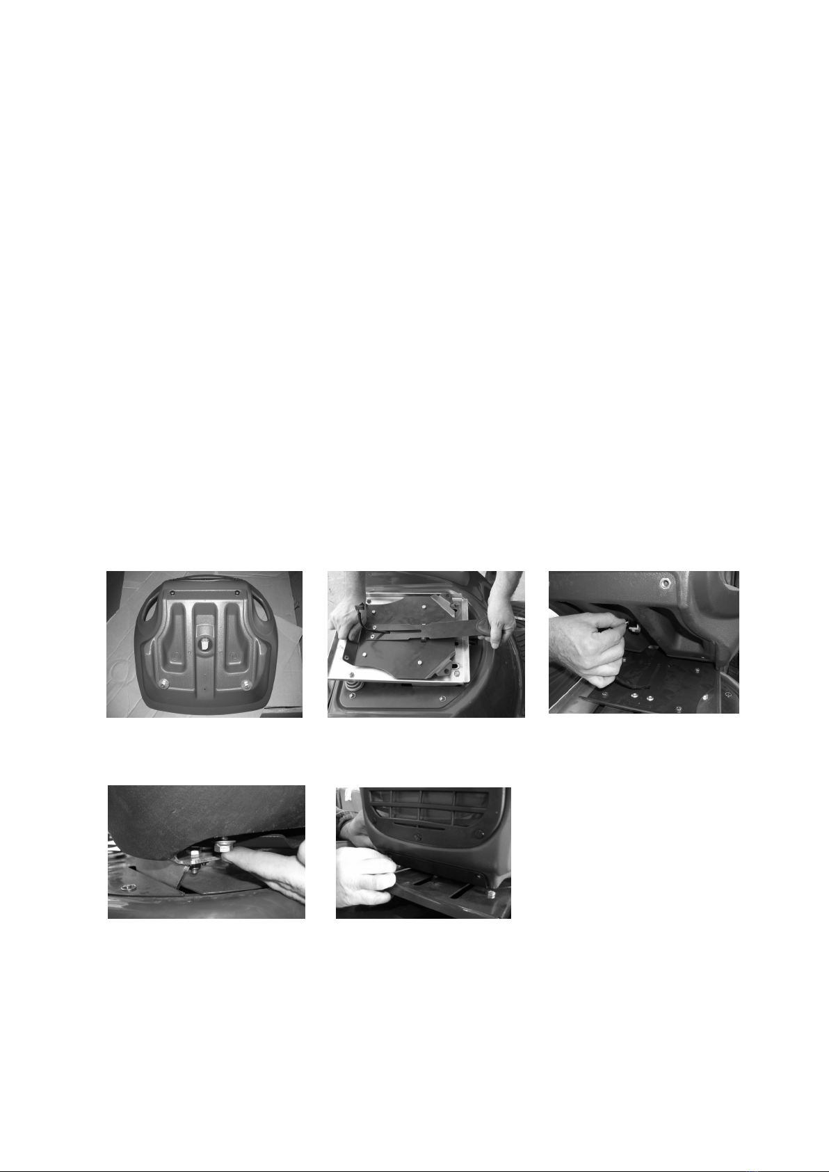
Pictorial Assembly Procedures - Seat
1/ Remove seat mounting
hardware from the seat.
2/ Raise seat adjustment lever
& slide the seat mount to the
forward most position.
3/ Connect the protruding wires
to the seat switch.
4/ Pass hex screw through seat
mount plate, then place plain washer
and spring washer as shown on hex
screw. Locate the hex screw into the
seat threaded insert and screw the
hex screw into the insert hand
(finger tight). Repeat on the other
side.
5/ Raise seat adjustment lever &
slide seat fully to the rear. Screw
the cap head screws into the rear
seat inserts by hand & tighten
using 5mm A/F Hex Allen Key
6/ Raise seat adjustment
lever & slide seat fully
forward. Using a 13mm
spanner tighten the front 2
seat mounts. Seat is now
ready for use.

OPERATING INSTRUCTIONS
Figure 1
Ignition Switch
Headlight Switch
Drive Pedal
Start Foot Switch
Cutting Height Adjustment Lever

The controls and their
functions are as
follows;
Ignition switch-
Used to start and stop engine.
Insert key, turn key all the way
right to start (3rd) position to start
engine. When key is released from
start (3rd) position it will return to
on | (2nd) position. Turn key all the
way left to off O (1st) position to
stop engine. Remove key from off
O (1st) position to lock ignition
switch.
Throttle control lever-
Used to regulate engine speed and
cutter speed. Pull lever fully back
for slow engine speed. 13HP, 15HP
and 17HP push lever forward to the
orange line for fast engine speed.
18HP push lever forward to top of
slot for fast engine speed.
Choke control-
Used to start a cold engine. 18.5HP,
21HP & 18HP push throttle control
lever up into the choke position to
start cold engine. Pull throttle
control lever down into the orange
range after engine has started.
Headlight switch-
Used to turn headlight on or off.
With ignition switch in on | (2nd)
position, toggle switch lever back to
on | position to turn headlights on.
toggle switch lever forward to off O
position to turn headlights off.
Mowing attachment clutch/brake
control-
Used to start and stop mowing
attachment. With engine running at
fast speed, ease handle fully
backward to on | position to start
mowing attachment. Push handle
fully forward to off O position to
stop mowing attachment.
Cutting height adjustment
lever-
Used to change the mowing
attachment cutting height. To
raise cutting height, pull lever
towards you and up, stop at desired
cutting height and push lever into
adjacent notch. To lower cutting
height, pull towards you and lower
the lever to desired height and push
lever into adjacent notch.
Drive pedal-
Used to control an infinitely
variable ground speed between
zero and maximum in forward or
reverse. Also to select neutral.
With engine running push down
on front of pedal to travel
forward. With engine running
push down on back of pedal to
travel in reverse. When pressure
is released from front or back of
pedal it will return to neutral
position. It is not necessary to
return to neutral before changing
from forward to reverse or
reverse to forward.
Foot brake pedal-
Used to stop machine travel before
setting park brake. Push pedal
down to apply brake. Remove foot
from pedal to release brake.
Park brake lever-
Used to keep machine stationary.
With drive pedal in neutral position
and machine stationary push lever
down and away from you to the
‘ON’ position to apply brake. To
release brake simply bump lever
down and towards you, the spring
tension will return the lever to the
‘OFF’ position.
NOTE–Applying park brake
while machine is moving
and/or attempting to drive
off with the park brake not
fully in the off position will
damage the teeth of the
large sprocket.
Start Foot switch -
Used to ensure drive is in neutral
when starting engine electrically.
Place right foot on and depress foot
switch to start engine with ignition
key.
Fuel tap knob-
Used to shut off fuel line when
machine is transported or not in
operation to prevent fuel leakage.
Remove left hand side cover and
locate fuel tap at the bottom of the
fuel tank. Turn fuel tap knob to
right 1/4 turn to off position to shut
fuel line. Turn fuel tap knob to left
1/4 turn to on position to open fuel
line.
The instruments and
THEIR functions are as
follows;
Hourmeter-
Used to indicate the number of
hours the engine has operated.
Note:- If the ignition switch is in the
on position with the engine off the
hourmeter will continue to operate.
Fuel level windows-
Used to indicate fuel remaining in
fuel tank.
Oil level dipstick-
Used to indicate oil level in engine
when engine is not running. (Refer
to engine owners manual for
instructions on checking engine oil
level)
STARTING ENGINE
Electric starter:
Cold engine: Check engine oil
level, check fuel level, open fuel
line. To start engine, place throttle
control lever into choke position
(18.5HP, 21HP & 18HP Kohler),
ensure mowing attachment clutch/
brake control (manual or electrical)
is in the off O position, place right
foot on and depress start foot
switch , insert key in ignition switch,
turn key all the way right to start
(3rd) position, release key when
engine has started. Note:
Continuous cranking for more than
15 seconds can damage the starter
motor. Short starting cycles give
best starter motor life. Allow starter
motor to cool for 2 minutes before
attempting to restart engine. After
engine starts, move throttle control
out of the choke position and into
the orange range (18.5HP, 21HP &
18HP Kohler), move throttle control
lever to obtain desired engine
speed.
Hot engine:
To start engine, place throttle control
slightly past slow position, ensure
mowing attachment clutch/brake
control (manual or electrical) is in the
off O position, place right foot on and
depress foot switch plate, insert key in
ignition switch,
OPERATING INSTRUCTIONS

turn key all the way right to start
(3rd) position, release key when
engine has started. Move throttle
control lever to obtain desired
engine speed.
Cold engine:
Check engine oil level, check fuel
level, open fuel line. To start
engine, place throttle control lever
in fast position, place choke control
into choke position, ensure mowing
attachment clutch/brake control
(manual or electrical) is in the off O
position, insert key in ignition
switch, turn key to the right to on |
(2nd) position. Ensure park brake is
applied, open bonnet, grasp starter
grip and pull lightly until resistance
is felt, then pull rapidly. Do not
allow starter grip to snap back
against engine, return starter grip
gently to prevent damage to starter
cord. After engine starts gradually
push choke knob fully in, move
throttle control lever to obtain
desired engine speed.
Hot engine:
To start engine, place throttle
control slightly past slow position,
ensure mowing attachment clutch/
brake control (manual or electrical)
is in the off O position, insert key in
ignition switch, turn key to the right
to on | (2nd) position. Ensure
park brake is applied, open bonnet,
grasp starter grip and pull lightly
until resistance is felt, then pull
rapidly. Do not allow starter grip to
snap back against engine, return
starter grip gently to prevent
damage to starter cord. When
engine has started move throttle
control lever to obtain desired
engine speed.
STOPPING ENGINE
When stopping engine, ensure
mowing attachment clutch/brake
control (manual or electrical) is in
the off position, return throttle to
slow position, turn ignition switch to
the off O (1st) position.
DRIVING - TO TRAVEL
MACHINE FORWARD OR
REVERSE:
With engine running set throttle
control lever to obtain desired
engine speed. Apply downward
pressure on front of drive pedal
with toes to travel forward, or
apply downward pressure on back
of drive pedal with heel to travel
in reverse. It is not necessary to
apply foot brake before changing
from forward to reverse or
reverse to forward. The amount
of pressure can be used to
control the ground speed, light
pressure will give a slow ground
speed, heavy pressure will give a
fast ground speed. Heavy
pressure may also be required
when travelling up slopes or
when heavy loads are being
towed or carried. Excessive
pressure should not need to be
applied to the drive pedal to
obtain a fast ground speed. When
operating the mower on slopes
greater than 10 degrees but less
than 15 degrees for a prolonged
period, you may experience minor
clutch fade, should this occur,
vary your mowing style eg: mow
around some flat areas, then the
slope followed by the flat area
again. This will allow the drive to
cool before travelling up the slope
again.
NOTE:
When mowing slopes keep
clutch pedal in forward or
reverse, depending on the
direction of the machine.
The low gearing will
prevent it from picking up
excessive speed. If very
steep, it may be necessary
to throttle back slightly and
or apply a light pedal
pressure to the opposite
clutch plate. i.e. move
clutch pedal into reverse
when going forward down
a slope or into forward
when reversing down a
slope. Ensure that when
pressure is applied to the
drive pedal the back wheel/
s start rotating or damage
will occur to drive system.
NOTE–Do Not mow either
direction on slopes beyond
15 degrees (1 in 3.75).
TO STOP MACHINE TRAVEL
ENGINE RUNNING:
The drive pedal may be used to
stop the machine. If traveling
forward push the pedal into reverse
until machine stops, then bring the
pedal back to neutral position or
vice versa if traveling in reverse.
Should failure of the drive system
occur during operation use the foot
brake pedal to stop machine travel.
ENGINE STOPPED:
Use foot brake pedal only.
NOTE:
Damage to clutch cone will
occur if clutch pedal is used
to stop machine travel with
the engine not running.
MANOEUVRING:
Due to the heel and toe type action
of the drive pedal, it is possible to
take the machine straight from
forward to reverse and vice versa
without applying the foot brake.
This instant forward and reverse
operation in conjunction with it
tight turning radius makes the
machine very maneuverable and
the sharpest turns can be
negotiated easily and quickly.
Note:
Take care when reversing,
always look in the direction
of intended travel before
changing direction.
DIFFERENTIAL OPTION:
The differential is used to permit
the back wheels to rotate at
different speeds when maneuvering
tight turns avoiding wheel slip
which may damage the lawn.
TRANSPORTING
If your machine is transported
regularly from site to site, especially
by trailer, it is recommended to
either adjust clutch plates wide
apart (re-tighten bolts) or place
cardboard between clutch cone and
clutch plates to avoid damaging the
clutch cone.

BEFORE EACH USE
BEFORE EACH USE
BEFORE EACH USE
Change engine oil - Clean machine - Lubricate as per required
DATE / / HOURS..........................DEALER................................................
MAINTENANCE SCHEDULE
Check engine oil level, adjust if required
Check engine air cleaner foam pre-cleaner, service if req
Check engine rotating screen/finger guard, clean if req
Check engine air inlet console screen, clean if required
Check operation of safety switches, service if required
Check foot brake operation, adjust if required
Lubricate as per required
Check tyre pressures, adjust if required
Grease stub axles
Check mowing attachment cutter blades, bolts, nuts, disc/s,
housing, and guards for wear or damage, replace if required
Check for loose fasteners, tighten if required
BEFORE STORAGE
BEFORE STORAGE
BEFORE STORAGE
EVERY 5 HOURS
EVERY 5 HOURS
EVERY 5 HOURS
Check engine oil level, adjust if required Lubricate chains(motorcycle chainlube preferred)
Check engine air cleaner foam pre-cleaner, service if req
Check engine rotating screen/finger guard, clean if required
Check engine air inlet console screen, clean if required*
*Service more often under dusty conditions, or where air born debris is present
1 MONTH OR 5 HOURS W
1 MONTH OR 5 HOURS W
1 MONTH OR 5 HOURS WHICH EVER OCCURS FIRST
HICH EVER OCCURS FIRST
HICH EVER OCCURS FIRST
Change engine oil
Check engine air cleaner foampre-cleaner, service if required
Check engine rotating screen/finger guard, clean if required
Check engine air inletconsole screen, clean if required
Check foot brake operation, adjust if required
Check operation of safety switches, service if required
Check tyre pressures, adjust if required
Grease stub axles
Check for loose fasteners, tighten if required
Check clutcharm action, adjust if required
Check mowing attachment cutter blades, bolts, nuts, disc/s,
housing , and guards for damage, replace if required
DATE / / HOURS..........................DEALER................................................
*Service more often under dusty conditions, or where air borne debris is present
3 MONTH OR 25 HOURS
3 MONTH OR 25 HOURS
3 MONTH OR 25 HOURS WHICH EVER OCCURS FIRST
WHICH EVER OCCURS FIRST
WHICH EVER OCCURS FIRST
Change engine oil if operating under heavy load or high ambient
temperature
Check engine air cleaner foampre-cleaner, service if required *
Check engine rotating screen/finger guard, clean if required *
Check engine air inletconsole screen, clean if required*
Check foot brake operation, adjust if required
Check operation of safety switches and replace if required
Check tyre pressures, adjust if required
Grease stub axles *
Check for loose fasteners, tighten if required
Check battery condition, service if required
Check mowing attachment cutter blades, bolts, nuts, disc/s, hous-
ing, and guards for wear or damage, replace if required
Lubricate steering & drive chains (motorcycle chain lube preferred)
*Service more often under dusty conditions, or where air borne debris is present
6 MONTH OR 50 HOURS
6 MONTH OR 50 HOURS
6 MONTH OR 50 HOURS WHICH EVER OCCURS FIRST
WHICH EVER OCCURS FIRST
WHICH EVER OCCURS FIRST
Change engine oil
If fitted clean engine exhaust spark arrester
Check engine air cleaner foam pre-cleaner , service if required *
Check engine rotating screen/finger guard , clean if required*
Check engine air inletconsole screen clean if required *
Check foot brake operation and lining for ware, adjust or replace if
req. Check operation of safetyswitches, service if required
Check tyre pressures, adjust if required
Grease stub axles *
Check steering chain and sprockets or wear, adjust if required
Check mowing attachment cutter blades, bolts, nuts, disc/s, hous-
ing, and guards for wear or damage, replace if required
Check clutcharm action, adjust if required
Check belts for wear or damage, replace if required
Check drive chain and sprockets for wear, replace if required
If fitted dismantle, clean, re-grease, and reassemble differential
If fitted check mowingattachment brake pad for wear, replace if
required
If fitted check mowingattachment electric clutch brake air gap,
adjust if req
Check for loose fasteners, tighten if required
Check drive clutch plates and cone forwear or damage, adjust or
service if req
Check battery condition, service if required
Check & tighten if necessary the clamp around the lower boss of
the steering box where it mounts onto the lower steering shaft
Lubricate steering & drive chains (motorcycle chain lube preferred)
DATE / / HOURS..........................DEALER................................................

9 MONTHS OR 75 HOURS WHICH EVER OCCURS F
9 MONTHS OR 75 HOURS WHICH EVER OCCURS F
9 MONTHS OR 75 HOURS WHICH EVER OCCURS FIRST
IRST
IRST
Change engine oil if operating under heavy load or high ambient
temperature
Check engine air cleaner foampre-cleaner, service if required *
Check engine rotating screen/finger guard, clean if required *
Check engine air inletconsole screen, clean if required*
Check foot brake operation, adjust if required
Check operation of safety switches and replace if required
Check tyre pressures, adjust if required
Grease stub axles *
Check for loose fasteners, tighten if required
Check battery condition, service if required
Check mowing attachment cutter blades, bolts, nuts, disc/s, hous-
ing, and guards for wear or damage, replace if required
Lubricate steering & drive chains (motorcycle chain lube preferred)
12 MONTHS OR 100 HOURS WHICH EVER OCCURS FIRST
12 MONTHS OR 100 HOURS WHICH EVER OCCURS FIRST
12 MONTHS OR 100 HOURS WHICH EVER OCCURS FIRST
If fitted replace engine oil filter.
Change engine oil.
Check engine spark plug, clean, adjust, or replace if required.
If fitted clean engine exhaust spark arrester.
Check engine air cleaner foampre-cleaner, service if required *.
Check engine air cleaner cartridge, service if required*.
Clean engine cooling system*.
Check engine air inletconsole screen, clean if required*.
Replace in-line fuel filter.
Check foot brake operation and lining for ware, adjust or replace if
req.
Grease stub axles *.
Check tyre pressures, adjust if required.
Check operation of safety switches, service if required.
Check steering chain an sprockets or wear, adjust if required.
Check drive chain and sprockets for wear, replace if required.
Check belts for wear or damage, replace if required.
Check clutcharm action, adjust if required.
Re-tension rear wheel adaptor retaining nut/s.
If fitted re-tension differential outer gear retaining bolts.
Check battery condition, service if required.
If fitted check mowingattachment brake pad for wear, replace if
req.
If fitted check mowingattachment electric clutch brake air gap,
adjust if req.
Check for loose fasteners, tighten if required.
Check drive clutch plates and cone forwear or damage, adjust or
service if required.
Check clutcharm action, adjust if required.
Check mowing attachment cutter blades, bolts, nuts, disc/s, hous-
ing, and guards for wear or damage, replace if required.
Check & tighten if necessary the clamp around the lower boss of
the steering box where it mounts onto the lower steering shaft
Lubricate steering & drive chains (motorcycle chain lube preferred)
DATE / / HOURS..........................DEALER................................................
DATE / / HOURS..........................DEALER................................................
*Service more often under dusty conditions, or where air borne debris is present
15 MONTHS OR 125 HOURS WHICH EVER OCCURS FIRST
15 MONTHS OR 125 HOURS WHICH EVER OCCURS FIRST
15 MONTHS OR 125 HOURS WHICH EVER OCCURS FIRST
Change engine oil if operating under heavy load or high ambient
temperature.
Check engine air cleaner foampre-cleaner, service if required *.
Check engine rotating screen/finger guard, clean if required *.
Check engine air inletconsole screen, clean if required*.
Check foot brake operation, adjust if required.
Check operation of safety switches and replace if required.
Check tyre pressures, adjust if required.
Grease stub axles *.
Check battery condition, service if required.
Check for loose fasteners, tighten if required.
Check mowing attachment cutter blades, bolts, nuts, disc/s, hous-
ing, and guards for wear or damage, replace if required.
Lubricate steering & drive chains (motorcycle chain lube preferred)
*Service more often under dusty conditions, or where air borne debris is present
DATE / / HOURS..........................DEALER................................................
18 MONTHS OR 150 HOURS WHICH EVER OCCURS FIRST
18 MONTHS OR 150 HOURS WHICH EVER OCCURS FIRST
18 MONTHS OR 150 HOURS WHICH EVER OCCURS FIRST
*Service more often under dusty conditions, or where air borne debris is present
DATE / / HOURS..........................DEALER................................................
Change engine oil.
If fitted clean engine exhaust spark arrestor.
Check engine air cleaner foampre-cleaner, service if required *.
Check engine rotating screen/finger guard, clean if required *.
Check engine air inletconsole screen, clean if required*.
Check foot brake operation and lining wear, adjust or replace if req.
Check operation of safety switches, service if required.
Check tyre pressures, adjust if required.
Grease stub axles *.
Check steering chain and sprockets or wear, adjust if required.
Check belts for wear or damage, replace if required.
Check drive chain and sprockets for wear, replace if required.
If fitted dismantle, clean, re-grease, and reassemble differential.
If fitted check mowingattachment brake pad for wear, replace if
required.
If fitted check mowingattachment electric clutch brake air gap, ad-
just if req.
Check drive clutch plates and cone forwear or damage, adjust/
service if req.
Check clutcharm action, adjust if required.
Check battery condition, service if required.
Check for loose fasteners, tighten if required.
Check mowing attachment cutter blades, bolts, nuts, disc/s, housing,
and guards for wear or damage, replace if required.
Check & tighten if necessary the clamp around the lower boss of the
steering box where it mounts onto the lower steering shaft
Lubricate steering & drive chains (motorcycle chain lube preferred)

21 MONTHS OR 175 HOURS WHICH EVER OCCURS FIRST
21 MONTHS OR 175 HOURS WHICH EVER OCCURS FIRST
21 MONTHS OR 175 HOURS WHICH EVER OCCURS FIRST
Change engine oil if operating under heavy load or high ambient
temperature.
Check engine air cleaner foampre-cleaner, service if required *.
Check engine rotating screen/finger guard, clean if required *.
Check engine air inletconsole screen, clean if required*.
Check foot brake operation, adjust if required.
Check operation of safety switches and replace if required.
Check tyre pressures, adjust if required.
Grease stub axles *.
Check battery condition, service if required.
Check for loose fasteners, tighten if required.
Check mowing attachment cutter blades, bolts, nuts, disc/s, hous-
ing, and guards for wear or damage, replace if required.
Lubricate steering & drive chains (motorcycle chain lube preferred)
24 MONTHS OR 200 HOURS WHICH EVER OCCURS FIRST
24 MONTHS OR 200 HOURS WHICH EVER OCCURS FIRST
24 MONTHS OR 200 HOURS WHICH EVER OCCURS FIRST
*Service more often under dusty conditions, or where air borne debris is present
DATE / / HOURS..........................DEALER................................................
If fitted replace engine oil filter.
Change engine oil.
Check engine spark plug, clean, adjust, or replace if required.
If fitted clean engine exhaust spark arrestor.
Check engine air cleaner foam pre-cleaner , service if required *.
Check engine air cleaner cartridge, service if required.
Clean engine cooling system*.
Check engine air inlet console screen , clean if required *.
Replace in-line fuel filter.
Check foot brake operation and lining for ware, adjust or replace if
req.
Check operation of safety switches, service if required.
Check tyre pressures, adjust if required.
Grease stub axles *
Check steering chain and sprockets or wear, adjust if required
Check belts for wear or damage, replace if required.
Check drive chain and sprockets for wear, replace if required.
If fitted re-tension differential outer gear retaining bolts.
Re-tension rear wheel adapter retaining nut/s.
If fitted check mowingattachment brake pad for wear, replace if
required.
If fitted check mowingattachment electric clutch brake air gap,
adjust if req.
Check clutcharm action, adjust if required
Check battery condition, service if required
Check for loose fasteners, tighten if required
Check mowing attachment cutter blades, bolts, nuts, disc/s, hous-
ing , and guards for wear or damage, replace if required.
Check & tighten if necessary the clamp around the lower boss of
the steering box where it mounts onto the lower steering shaft
Lubricate steering & drive chains (motorcycle chain lube preferred)
*Service more often under dusty conditions, or where air borne debris is present
DATE / / HOURS..........................DEALER................................................
27 MONTHS OR 225 HOURS WHICH EVER OCCURS FIRST
27 MONTHS OR 225 HOURS WHICH EVER OCCURS FIRST
27 MONTHS OR 225 HOURS WHICH EVER OCCURS FIRST
Change engine oil if operating under heavy load or high ambient
temperature.
Check engine air cleaner foampre-cleaner, service if required *.
Check engine rotating screen/finger guard, clean if required *.
Check engine air inletconsole screen, clean if required*.
Check foot brake operation, adjust if required.
Check operation of safety switches and replace if required.
Check tyre pressures, adjust if required.
Grease stub axles *.
Check battery condition, service if required.
Check for loose fasteners, tighten if required.
Check mowing attachment cutter blades, bolts, nuts, disc/s, hous-
ing, and guards for wear or damage, replace if required
Lubricate steering & drive chains (motorcycle chain lube preferred)
*Service more often under dusty conditions, or where air borne debris is present
DATE / / HOURS..........................DEALER................................................
30 MONTHS OR 250 HOURS WHICH EVER OCCURS FIRST
30 MONTHS OR 250 HOURS WHICH EVER OCCURS FIRST
30 MONTHS OR 250 HOURS WHICH EVER OCCURS FIRST
Change engine oil.
If fitted clean engine exhaust spark arrestor.
Check engine air cleaner foam pre-cleaner , service if required *.
Check engine rotating screen/finger guard , clean if required*.
Check engine air inlet console screen , clean if required *.
Check foot brake operation and lining for ware, adjust or replace if
req.
Check operation of safety switches, service if required.
Check tyre pressures, adjust if required.
Grease stub axles *.
Check steering chain an sprockets or wear, adjust if required.
Check mowing attachment cutter blades, bolts, nuts, disc/s, hous-
ing, and guards for wear or damage, replace if required.
Check belts for wear or damage, replace if required
Check drive chain and sprockets for wear, replace if required
If fitted dismantle, clean, re-grease, and reassemble differential
If fitted check mowingattachment brake pad for wear, replace if
required
If fitted check mowingattachment electric clutch brake air gap,
adjust if req,
Check drive clutch plates and cone for wear or damage.
adjust or service if required.
Check clutcharm action, adjust if required.
Check battery condition, service if required.
Check for loose fasteners, tighten if require
Check & tighten if necessary the clamp around the lower boss of
the steering box where it mounts onto the lower steering shaft
Lubricate steering & drive chains (motorcycle chain lube preferred)
*Service more often under dusty conditions, or where air borne debris is present
DATE / / HOURS..........................DEALER................................................

33 MONTHS OR 275 HOURS WHICH EVER OCCURS FIRST
33 MONTHS OR 275 HOURS WHICH EVER OCCURS FIRST
33 MONTHS OR 275 HOURS WHICH EVER OCCURS FIRST
Change engine oil if operating under heavy load or high ambient
temperature
Check engine air cleaner foampre-cleaner, service if required *
Check engine rotating screen/finger guard, clean if required *
Check engine air inletconsole screen, clean if required*
Check foot brake operation, adjust if required
Check operation of safety switches and replace if required
Check tyre pressures, adjust if required
Grease stub axles *
Check mowing attachment cutter blades, bolts, nuts, disc/s, hous-
ing , and guards for wear or damage, replace if required
Check battery condition, service if required
Check for loose fasteners, tighten if required
Lubricate drive & steering chains (motorcycle chain lube preferred)
*Service more often under dusty conditions, or where air borne debris is present
DATE / / HOURS..........................DEALER................................................
36 MONTHS OR 300 HOURS WHICH EVER OCCURS FIRST
36 MONTHS OR 300 HOURS WHICH EVER OCCURS FIRST
36 MONTHS OR 300 HOURS WHICH EVER OCCURS FIRST
If fitted replace engine oil filter
Change engine oil
Check engine spark plug, clean, adjust, or replace if required
If fitted clean engine exhaust spark arrestor
Check engine air cleaner foam pre-cleaner, service if required *
Check engine air cleaner cartridge, service if required
Clean engine cooling system*
Check engine air inlet console screen , clean if required *
Replace in-line fuel filter
Check foot brake operation and lining for ware, adjust or replace if
req.
Check operation of safety switches, service if required
Check tyre pressures, adjust if required
Grease stub axles *
Check steering chain an sprockets or wear, adjust if required
Check mowing attachment cutter blades, bolts, nuts, disc/s, hous-
ing, and guards for wear or damage, replace if required
Check belts for wear or damage, replace if required
Check drive chain and sprockets for wear, replace if required
If fitted re-tension differential outer gear retaining bolts
Re-tension rear wheel adapter retaining nut/s
If fitted check mowingattachment brake pad for wear, replace if
required
If fitted check mowingattachment electric clutch brake air gap,
adjust if req
Check drive clutch plates and cone forwear or damage, adjust/
service if req
Check clutcharm action, adjust if required
Check battery condition, service if required
Check for loose fasteners, tighten if required
Check & tighten if necessary the clamp around the lower boss of
the steering box where it mounts onto the lower steering shaft
Lubricate drive & steering chains (motorcycle chain lube preferred)
*Service more often under dusty conditions, or where air borne debris is present
DATE / / HOURS..........................DEALER................................................
MAINTENANCE INSTRUCTIONS
MAINTENANCE INSTRUCTIONS
MAINTENANCE INSTRUCTIONS
Before servicing, disconnect spark
plug wire and ground it,
disconnect battery at negative
terminal, to prevent accidental
starting.
Reference to the left or right side of
the machine is determined by sitting in
the operating position.
IMPORTANT
If operating in conditions such as
those mentioned below, engine oil, air
filtering, chassis lubrication, greasing
and adjustments should be serviced
at more frequent intervals than
specified in this booklet.
a. Mowing in damp or wet conditions.
b. Mowing in rough or dusty
conditions.
c. Mowing in hilly areas under heavy
load.
Ensure machine has park brake
engaged when attempting to
start engine. Disengage park
brake before applying drive
pressure to clutch pedal.
Never alter factory setting of
maximum engine R.P.M.
STEERING –
Check, lubricate & adjust the steering chain
if necessary
Check & replace steering tie rod ball joints
if worn.
DIFFERENTIAL -
For models fitted with a differential it is
essential that the maintenance schedule
supplied be performed by your COX
INDUSTRIES Dealer. This will ensure the
differential has trouble free operation and
long service life.
CHECK ENGINE OIL LEVEL - Refer to
engine owners manual for correct method
to check engine oil level.
CHANGE ENGINE OIL -
Refer to engine owners manual for correct
method to change engine oil.
CHECK ENGINE AIR CLEANER FOAM
PRE-CLEANER -
Refer to engine owners manual for correct
method to check and service engine air
cleaner foam pre-cleaner.
CHECK ENGINE INLET VENTS -
If Vents are more than one quarter blocked
by debris clean Vents.
Wipe vents with hand, rag or brush to
remove debris from vent openings.
CHECK ENGINE ROTATING
SCREEN/FINGER GUARD –
Refer to engine owners manual for correct
method to check and clean engine rotating
screen /debris guard.

CHECK FOOT BRAKE
OPERATION -
Measure the distance between the under
side of the pedal rubber to footrest by
holding pedal down using hand pressure. If
less than 50mm (2”) adjust brake. Adjust
brake by tightening the nyloc nut on brake
pull rod (pedal end) to give 90mm (3 1/2”)
between the brake pedal rubber and
footrest (using hand pressure on brake
pedal).
CHECK TYRE PRESSURES –
Adjust front and rear tyre pressure to
100kPa (15psi).
CHECK OPERATION OF SAFETY
SWITCHES -
Foot Switch - Sit on seat with cutter
disengaged, (manual or electric control)
attempt to start engine without using the
foot switch. Engine should not start.
Disengagement Switch - Sit on seat with
foot on foot switch and cutter engaged,
(manual or electric control) attempt to start
engine. Engine should not start.
Seat Switch - Sit on seat and start engine,
engage cutter, (manual or electric control)
and lift weight from seat. Engine should
stop.
CHECK FOR LOOSE
FASTENERS -
TORQUE SETTINGS
1/4” UNC BOLT/NUT 10Nm (84lbf in)
5/16” UNF BOLT 23Nm (17lbf ft)
5/16” UNC BOLT/NUT 20Nm (180lbfin)
3/8” UNF BOLT 41Nm (30lbf ft)
3/8” UNC BOLT/NUT 36Nm (27lbf ft)
7/16” UNF BOLT 68Nm (50lbf ft)
1/2” UNC BOLT/NUT 90Nm (66lbf ft)
3/8” UNF BOLT P/N B0620F CLUTCH SHAFT
ONLY 35Nm (26lbf ft)
6mm BOLT/NUT 9Nm (80lbf in)
8mm BOLT/NUT 30Nm (22lbf ft)
20mm NUT 100Nm (74lbf ft)
5/8” UNF NUT 100Nm (74lbf ft)
CHECK BATTERY CONDITION -
Loosen knob on the console hatch, slide
hatch up, then pull out at the base (slide
fuel tank out a small distance) and remove
hatch. Pull battery out. Remove battery
caps and adjust electrolyte levels between
upper & lower level marks on battery case
using distilled water. Place battery in its
recess. (Make sure battery leads are clear of
steering universal). Install the console
hatch by inserting into console top, push
hatch bottom and fuel tank into console,
push down to engage pins in chassis,
tighten top knob by hand.
GREASE STUB AXLES -
Clean grease nipple, use grease gun and
general purpose grease to force old grease
from top and bottom of front axle bushes.
Jack up front of machine if grease is not
released from bottom of bush.
REMOVE MOWING
ATTACHMENT -
With engine off fully lower mowing
attachment, and using spring hook and
tommy bar supplied, disconnect the three
springs below the front axle beam (warning,
springs are under tension). Disconnect rear
lifting link, push attachment to the rear to
loosen vee belt, remove vee belt from the
rear pulley then attachment pivot rod. Turn
steering to full left hand lock and slide
attachment from under machine to the right
hand side. To refit, reverse the above
procedure.
REPLACE P.T.O. TO CUTTER BELT -
Engage park brake, place mowing
attachment in lowest position remove the
front ends of the three springs from under
front axle beam using spring hook and
tommy bar supplied, (caution springs are
under tension) remove R Pin from rear
lifting link, disconnect link from mowing
attachment and push mowing attachment
to the rear to loosen belt. Remove belt
from pulleys and replace with new belt,
reverse the above procedure to re-tension
belt.
REPLACE BLADES -
Stop engine. Remove spark plug lead. Lift
windrower and raise cutter to highest
position. If necessary simply remove the
blade bolt and nut using a suitable spanner
and replace all blades, bolts and nuts. For
40" mowing attachment it is advisable to
remove mowing attachment for blade
replacement. Tighten blade nut to (36-
40Nm). Do not over-tighten.
CLUTCH PLATE ADJUSTMENT –Start
engine and run for approx 1 min at about
half throttle, switch engine off, loosen the
four square head set screws on the clutch
plates using the tube spanner (AM006C1)
and tommy bar (AM007). Insert the two
clearance gauges supplied, one between
the forward clutch plate and cone and the
other in the reverse side and hook them
onto the intershaft. Slide both clutch plates
against the clearance gauges and clutch
cone. Tighten the set screws firmly onto the
flat machined on the intershaft. (Do not
over-tighten set screws). Remove gauges.
Under no circumstances allow
grease or oil to come into
contact with the Clutch Cone
or Clutch Plates. Should this
problem occur, clean off
immediately with petrol whilst
surface areas are cool and
allow to dry before operating
machine.
REPLACE DRIVE CHAIN -
Engage park brake, jack up rear of
machine, and remove L/H wheel. Push
chain tensioner arms, one at a time, away
from chain and using a suitable spanner
tighten pivot bolt lock nuts to hold them
out. Release park brake then turn rear axle
to bring chain into a suitable position for
removal of the chain connecting link.
Remove connecting link and chain. Inspect
both sprockets for wear or damage, replace
if necessary. Install new chain and
connecting link with the link clip between
the wheel and chain. Release pivot arm
nuts until arm moves freely back to chain.
Engage park brake, install wheel and lower
machine.
SEAT ADJUSTMENT -
Remove the front two bolts and the lower
rubber bushes from the spacer sleeves. Lift
the front of the seat, insert the spacer
sleeves with the top rubber bushes into the
desired seat position hole. Install lower
rubber bushes and bolts and tighten.
CLEANING AND POLISHING PLASTIC
BONNET & FOOT PAN -
To keep scratches on bonnet to minimum,
do not rub or brush off with bare hands, use
a soft cloth or a light flow of compressed
air. For dirt, wash with a steady stream of
water only (no detergent), then blow off
excess water with air. To polish remove
excess dust or dirt. When surface is dry,
spray on an automotive type plastic
preservative and leave on for 30 to 60
seconds. Using a dry soft cloth (i.e.
cheesecloth) wipe off to bring up lustre.
CLEANING MACHINE WITH WATER
PRESSURE –
Allow machine to cool down (min 2 hrs)
before hosing down. Start engine and
engage drive and cutting systems to clear
water from pulleys, belts and clutch areas.
Stop engine and allow machine to dry.
Lubricate as per lubrication chart before
storage.
GENUINE SPARE PARTS -
Always use Genuine Cox Factory Made
Spare Parts. Use of non genuine COX
spares will void your warranty.
SAFETY FIRST -
The use of any mechanical appliance can
cause injury if incorrect procedures are
used. Please ensure that all family
members of intended operators read this
manual and safety instructions thoroughly.
MAINTENANCE INSTRUCTIONS
MAINTENANCE INSTRUCTIONS
MAINTENANCE INSTRUCTIONS CONT.
CONT.
CONT.
We are proud that you have purchased a Cox product and urge you to follow these instructions to obtain the maximum life
for your machine. If in doubt check with your supplier.

MODELS
MODELS
MODELS 9005F,
9005F,
9005F, 9005
9005
9005J
J
J, 9006D,
, 9006D,
, 9006D,
A10406C
A10406C
A10406C &
&
&
A10406D
A10406D
A10406D:
:
:-
-
-
BODY COMPONENTS & TOOL KIT
BODY COMPONENTS & TOOL KIT
BODY COMPONENTS & TOOL KIT
ITEM PART NO. DESCRIPTION QTY
1 90096 Console Lug 1
2 RECS6 Receptacle 6
3 RETP6 Retainer, Plastic 6
4 STDR614 Stud 4
5 STDR622 Stud 2
6 BHSSM5X12 Screw 4
7 NM5NT Nut 4
8 WG06X08 Grommet, Wiring 2
9 90034 Left Side Cover 1
10 90035 Right Side Cover 1
11 90033 Battery Cover 1
12 90084 Sub-Assy, Bumper Bar 1
12.1 90070 Bumper Bar 1
12.2 90020 Support, Bumper Bar 1
12.3 SH0825M Screw 2
12.4 NHM8 Nut 2
13 NM6NT Nut 6
14 NM8NT Nut 2
15 90032 Dashboard Steering Column Cover 1
16 DEC182 Decal, Throttle Control (13HP 15HP 17HP only) 1
DEC176 Decal, Dash (18HP only) 1
17* DEC181 Decal, Dash, Cutter Engage (13HP Only) 1
17** DEC175 Decal, Cutter Slot And Light 15HP 17HP 18HP 1
18 90063 Rubber Dash Insert, Disengagement 1
19 90064 Rubber Dash Insert, Throttle 1
ITEM PART NO. DESCRIPTION QTY
20* 90067 Sun Glass Holder 13HP 1
20** AM211 Hour Meter 15HP 17HP 18HP 1
21** 90128 Switch, Light 1
22 90129 Ignition Switch 1
23 90076 Battery Spill Mat 1
24 B0625M Bolt 6
25 90140 Bush, Bumper 6
26 BHSSM5X12 Screw 5
27 NM5NT Nut 5
28 DEC201 Decal, Instruct, Operation 1
29 90079 Rear Cover, Transmission Housing 1
30 DEC08505K Decal, Warning, Fuel 1
31 DEC135 Decal, Caution. Hot Muffler 1
* Denotes 13HP Models Only
** Denotes 15HP, 17HP & 18HP Models Only
TOOL KIT
ITEM PART NO. DESCRIPTION QTY
1 AM006C1 Spanner, Tube, Clutch Plate 1
2 AM007 Bar, Tommy 1
3 AM295 Spanner, Tube, Spark Plug 1
4 13126 Gauge, Clutch Clearance 2
5 13127 Hook, Spring Pull 1
6 90134 Key, Ignition Switch 2

MODELS
MODELS
MODELS 9006J, 9007E,
9006J, 9007E,
9006J, 9007E, 9008E, A10406J, A10407E
9008E, A10406J, A10407E
9008E, A10406J, A10407E
&
&
&
A10408E
A10408E
A10408E
:
:
:-
-
-
BODY COMPONENTS & TOOL KIT
BODY COMPONENTS & TOOL KIT
BODY COMPONENTS & TOOL KIT
TOOL KIT
TOOL KIT
ITEM PART NO. DESCRIPTION QTY
1 AM006C1 Spanner, Tube, Clutch Plate 1
2 AM007 Bar, Tommy 1
3 AM295 Spanner, Tube, Spark Plug 1
4 13126 Gauge, Clutch Clearance 2
5 13127 Hook, Spring Pull 1
6 90134 Key, Ignition Switch 2
ITEM PART N0. DESCRIPTION QTY
1 90033 Battery Cover 1
DEC201 Decal, Instruction, Operation 1
2 90034 Left Side Cover 1
3 90035 Right Side Cover 1
4 90045 Right Foot Mat 1
5 90046 Left Foot Mat 1
6 90047 Hand Brake Shroud 1
7 90048 Height Adjustment Shroud 1
8 90056 Sub-Assy, Steering Wheel 1
9 90072 Centre Foot Mat 1
10 90075 Mud Flap 1
11 90076 Battery Spill Mat 1
12 90020 Support, Bumper Bar, Charcoal Grey 1
13 90070 Bumper Bar 1
14 NHM8 Nut 2
15 SH0825M Screw 2
16 90085 Sub-Assy, Bonnet 15 HP & 17HP 1
90174 Sub-Assy, Bonnet 18 HP
17 90032 Dashboard Steering Column Cove 1
18 90063 Rubber Dash Insert, Disengagement 1
19 90064 Rubber Dash Insert, Throttle 1
20 90128 Switch, Light 1
21 90129 Ignition Switch 1
22 AM211 Hour Meter 1
23 DEC175 Decal, Cutter Slot And Light 1
24 DEC182 Decal, Throttle Control 15 HP & 17HP 1
ITEM PART N0. DESCRIPTION QTY
DEC176 Decal, Throttle Control 18 HP
25 90096 Console Lug 1
26 90132 Rivet, Plastic Grip Range 4.6m 5
27 90140 Bush, Bumper 6
28 90205 Pan, Foot, Plastic, Red 1
29 90247 Cover, Inspection, Top, Grey 1
30 90248 Sub-Assy, Mechanism, Slide, Seat 1
31 90250 Sub-Assy, Seat, New Era Stockman 1
32 B0625M Bolt 6
33 BHSSM5X12 Button Head Cap Screw 7
34 NM5NT Nut 5
35 NM6NT Nut 32
36 NM8NT Nut 4
37 RECS4 Receptacle, 1/4turn, Clip-On 4
38 RECS6 Receptacle, 1/4turn, Slip On 6
39 RETP6 Retainer, 1/4turn, Plastic 6
40 RETS4 Retainer, 1/4turn, Steel 4
41 SH0616M Screw 26
42 SH0825M Screw 2
43 SP1PNOSM Switch, Plunger 1
44 SPPK5X16 Pt Screw 8
45 STDR414 Stud, 1/4turn, Bail 4
46 STDR614 Stud, 1/4turn, Ring 4
47 STDR622 Stud, 1/4turn, Ring 2
48 W041018 Washer 18
49 WG06x08 Grommet, Wiring 6
DEC127 Decal, Warning, Mount This Side Only 1

MODELS A12608G
MODELS A12608G
MODELS A12608G,
,
,
A12708G, A12608H
A12708G, A12608H
A12708G, A12608H
, A13809H
, A13809H
, A13809H:
:
:-
-
-
BODY COMPONENTS & TOOL KIT
BODY COMPONENTS & TOOL KIT
BODY COMPONENTS & TOOL KIT
TOOL KIT
ITEM PART NO. DESCRIPTION QTY
1 AM006C1 Spanner, Tube, Clutch Plate 1
2 AM007 Bar, Tommy 1
3 AM295 Spanner, Tube, Spark Plug 1
4 13126 Gauge, Clutch Clearance 2
5 13127 Hook, Spring Pull 1
6 90134 Key, Ignition Switch 2
TOOL KIT
ITEM PART NO. DESCRIPTION QTY
DEC176 Decal, Throttle Control 18 HP
25 90096 Console Lug 1
26 90132 Rivet, Plastic Grip Range 4.6m 5
27 90140 Bush, Bumper 6
28 90205 Pan, Foot, Plastic, Red 1
29 90247 Cover, Inspection, Top, Grey 1
30 90248 Sub-Assy, Mechanism, Slide, Seat 1
31 90250 Sub-Assy, Seat, New Era Stockman 1
32 B0625M Bolt 6
33 BHSSM5X12 Button Head Cap Screw 7
34 NM5NT Nut 5
35 NM6NT Nut 32
36 NM8NT Nut 4
37 RECS4 Receptacle, 1/4turn, Clip-On 4
38 RECS6 Receptacle, 1/4turn, Slip On 6
39 RETP6 Retainer, 1/4turn, Plastic 6
40 RETS4 Retainer, 1/4turn, Steel 4
41 SH0616M Screw 26
42 SH0825M Screw 2
43 SP1PNOSM Switch, Plunger 1
44 SPPK5X16 Pt Screw 8
45 STDR414 Stud, 1/4turn, Bail 4
46 STDR614 Stud, 1/4turn, Ring 4
47 STDR622 Stud, 1/4turn, Ring 2
48 W041018 Washer 18
49 WG06x08 Grommet, Wiring 6
DEC127 Decal, Warning, Mount This Side Only 1
ITEM PART NO. DESCRIPTION QTY
1 90033 Battery Cover 1
DEC201 Decal, Instruction, Operation 1
2 90034 Left Side Cover 1
3 90035 Right Side Cover 1
4 90045 Right Foot Mat 1
5 90046 Left Foot Mat 1
6 90047 Hand Brake Shroud 1
7 90048 Height Adjustment Shroud 1
8 SW14H Steering Wheel incl Cover 1
A102164 Adaptor, Console (Str Wheel) 1
9 90072 Centre Foot Mat 1
10 90075 Mud Flap 1
11 90076 Battery Spill Mat 1
12 90020 Support, Bumper Bar, Charcoal Grey 1
13 90070 Bumper Bar 1
14 NHM8 Nut 2
15 SH0825M Screw 2
16 9008508H Sub-Assy, Bonnet 15HP, 17HP, 15.5HP, 17.5HP, 18.5HP 1
A126085 Sub-Assy, Bonnet 21 HP 1
9017408H Sub-Assy, Bonnet 18 HP 1
17 90032 Dashboard Steering Column Cove 1
18 90063 Rubber Dash Insert, Disengagement 1
19 90064 Rubber Dash Insert, Throttle 1
20 90128 Switch, Light 1
21 90129 Ignition Switch 1
22 AM211 Hour Meter 1
23 DEC175 Decal, Cutter Slot And Light 1
24 DEC182 Decal, Throttle Control 15HP,17HP,15 .5HP,17.5HP,18.5HP,21HP 1

MODEL
MODEL
MODELS
S
S
9005
9005
9005F, 9005
F, 9005
F, 9005J, 9006J & 9007E
J, 9006J & 9007E
J, 9006J & 9007E:
:
:-
-
-
BO
BO
BONNET
NNET
NNET
COMPONENTS
COMPONENTS
COMPONENTS
(13HP 15HP & 17HP ONLY)
(13HP 15HP & 17HP ONLY)
(13HP 15HP & 17HP ONLY)
ITEM PART NO. DESCRIPTION QTY
1 90041 Grille 1
2 90042 Left Bonnet Vent 1
3 90043 Right Bonnet Vent 1
4 DEC180 Badge, Bonnet New Era 1
5** 15132 Globe 15HP 17HP 1
6 90031 Bonnet 1
7** 90038 Head Light Reflector 15HP 17HP 1
8* 90164 Cover, Centre/Grille, Air Intake 13HP 1
8** 90039 Head Light Lens 15HP 17HP 1
9 90040 Air Duct Intake 1
10 90021B06A Hinge, Bonnet New Era 1
11 90130 Buffer, Rubber 2
12 SPPK5X16 Screw 6
13 SPPK5X20 Screw 4
14 CHSSM5X16 Screw 6
15 CHSSM5X20 Screw 2
ITEM PART NO. DESCRIPTION QTY
16 CHSSM5X12 Screw 4
17 W03S Washer 7
18** SPPK3X8 Screw 15HP 17HP 1
19 90147 Shield, Heat, Bonnet 1
PR0207 Rivet, Heat Shield 3
20 DEC196 Decal, Bonnet, 13.0hp-32 LA 1
20 DEC188 Decal, Bonnet, 15.0hp-32 D 1
20 DEC189 Decal, Bonnet, 15.0hp-32 LA 1
20 DEC194 Decal, Bonnet, 17.0hp-32 D 1
20 DEC195 Decal, Bonnet, 17.0hp-32 LA 1
20 DEC190 Decal, Bonnet, 17.0hp-40 D 1
20 DEC191 Decal, Bonnet, 17.0hp-40 LA 1
* Denotes 13.0HP models only
** Denotes 15.0HP and 17.0HP models only
For item no20 - "LA" denotes Live Axle
- "D"denotes Differential Axle

MODEL 9008E
MODEL 9008E
MODEL 9008E:
:
:-
-
-
BO
BO
BONNET
NNET
NNET
COMPONENTS
COMPONENTS
COMPONENTS
(15HP & 17HP ONLY)
(15HP & 17HP ONLY)
(15HP & 17HP ONLY)
ITEM PART NUMBER DESCRIPTION QTY
1 90041 Grille 1
2 90042 Left Bonnet Vent 1
3 90043 Right Bonnet Vent 1
4 DEC180 Badge, Bonnet New Era 1
5 15132 Globe 15HP 17HP 1
6 90031 Bonnet 1
7 90038 Head Light Reflector 15HP 17HP 1
8 90039 Head Light Lens 15HP 17HP 1
9 90040 Air Duct Intake 1
10 9002107A Hinge, Bonnet New Era 1
11 90130 Buffer, Rubber 2
12-15 SPPK5X16 Screw 18
16 CHSSM5X12 Screw 4
17 W03S Washer 4
18 SPST04GX0.37 Screw 15HP 17HP 1
19 90147 Shield, Heat, Bonnet 1
PR0207 Rivet, Heat Shield 3
20 DEC188 Decal, Bonnet, 15.0hp-32 DP 1
20 DEC189 Decal, Bonnet, 15.0hp-32 LP 1
20 DEC194 Decal, Bonnet, 17.0hp-32 DP 1
20 DEC195 Decal, Bonnet, 17.0hp-32 LP 1
20 DEC190 Decal, Bonnet, 17.0hp-40 DP 1
20 DEC191 Decal, Bonnet, 17.0hp-40 LP 1
For item no20 - "LP" denotes Live Axle
- "DP" denotes Differential Axle

MODEL A12608G, A12608H:
MODEL A12608G, A12608H:
MODEL A12608G, A12608H:-
-
-
BO
BO
BONNET
NNET
NNET
COMPONENTS
COMPONENTS
COMPONENTS
(15HP, 15.5HP, 17HP, 17.5HP ONLY)
(15HP, 15.5HP, 17HP, 17.5HP ONLY)
(15HP, 15.5HP, 17HP, 17.5HP ONLY)
ITEM PART NUMBER DESCRIPTION QTY
1 90041 Grille 1
2 90042 Left Bonnet Vent 1
3 90043 Right Bonnet Vent 1
4 DEC180 Badge, Bonnet New Era 3
5 15132 Globe 1
6 9003108G Bonnet incl Mountings and Spacers 1
A126044 Mounting, Side, Bonnet 2
A126045 Spacer, Mounting, Side, Bonnet 2
7 90038 Head Light Reflector 1
8 90039 Head Light Lens 1
9 90040 Air Duct Intake 1
10 9002107A Hinge, Bonnet New Era 1
11 90130 Buffer, Rubber 2
12-15 SPPK5X16 Screw 22
16 CHSSM5X12 Screw 4
17 W03S Washer 4
18 SPST04GX0.37 Screw 1
19 90147 Shield, Heat, Bonnet 1
PR0207 Rivet, Heat Shield 3
20 DEC189 Decal, Bonnet, 15.5hp-32 LP 1
20 DEC195 Decal, Bonnet, 17.5hp-32 LP 1
20 DEC190 Decal, Bonnet, 17.5hp-40 DP 1
20 DEC191 Decal, Bonnet, 17.5hp-40 LP 1

MODEL A12608G, A12608H:
MODEL A12608G, A12608H:
MODEL A12608G, A12608H:-
-
-
BO
BO
BONNET
NNET
NNET
COMPONENTS
COMPONENTS
COMPONENTS
(18.5HP, 21HP ONLY)
(18.5HP, 21HP ONLY)
(18.5HP, 21HP ONLY)
ITEM PART NUMBER DESCRIPTION QTY
1 15132 Globe 18.5HP 21HP 1
2 9002107A Hinge, Bonnet New Era 1
3 90038 Head Light Reflector 18.5HP 21HP 1
4 90039 Head Light Lens 18.5HP 21HP 1
5 90040 Air Duct Intake 1
6 90041 Grille 1
7 90042 Left Bonnet Vent 1
8 90043 Right Bonnet Vent 2
9 90130 Buffer, Rubber 2
10 9003108G Bonnet incl Mountings and Spacers 1
11 A126044 Mounting, Side, Bonnet 2
12 A126045 Spacer, Mounting, Side, Bonnet 2
13 90147 Shield, Heat, Bonnet 18.5HP 1
A126147 Shield, Heat, Bonnet 21HP 1
14 AM096 Clip 1
15 DEC180 Badge, Bonnet New Era 3
16 PR0207 Rivet, Heat Shield 3
17 SPPK5X16 Screw 22
18 SPST04CX0.37 Screw 18.5HP 21HP 1
DEC263 Decal, Bonnet, 18.5HP-32 LP 1
DEC264 Decal, Bonnet, 21HP-32 LP 1
This manual suits for next models
14
Other Stockman Lawn Mower manuals


