Stoneridge OPTIMO 2 User manual

DD 56065 Rev 08 1 ©Stoneridge Electronics Ltd
Stoneridge Optimo² Manual
Stoneridge Electronics Ltd
Copyright
The information contained in this document is the property of Stoneridge
Electronics Ltd. and should not be reproduced, revealed or appropriated,
either in whole or in part, without the written authority of Stoneridge, Inc.

2
Contents
1. Optimo² Kit .................................................................................................................................................................................... 3
2. Optimo² Switching On ................................................................................................................................................................... 3
3. Optimo² Main Screen .................................................................................................................................................................... 4
4. Optimo² Features .......................................................................................................................................................................... 4
5. Optimo² Sleep Mode & Switching Off ........................................................................................................................................... 5
6. Getting Started.............................................................................................................................................................................. 6
6.1. Task Bar Icons .................................................................................................................................................................... 6
6.1.1. Workshop Settings.................................................................................................................................................... 6
6.1.2. Connecting to Wi-Fi .................................................................................................................................................. 8
6.1.3. Wireless Connections ............................................................................................................................................... 8
6.2. Connecting to the Tachograph........................................................................................................................................... 9
6.3. Calibrating and Programming ............................................................................................................................................ 9
7. Optimo² – MKIII Programmer –Main screens ............................................................................................................................ 10
7.1. Read and modify data...................................................................................................................................................... 11
7.2. Tachograph Information .................................................................................................................................................. 13
7.3. Bench test ........................................................................................................................................................................ 14
7.4. Fixed distance 1 ............................................................................................................................................................... 15
7.5. Speed simulator ............................................................................................................................................................... 16
7.6. C3 RPM test...................................................................................................................................................................... 16
7.7. DTCs ................................................................................................................................................................................. 17
7.8. k factor test...................................................................................................................................................................... 17
7.9. DIL calculate..................................................................................................................................................................... 18
7.10. Fixed distance 2 ............................................................................................................................................................... 19
7.11. Rolling road ...................................................................................................................................................................... 20
7.12. Clock test.......................................................................................................................................................................... 22
7.13. PIN.................................................................................................................................................................................... 22
7.14. Serial data test ................................................................................................................................................................. 23
7.15. CANbus data test ............................................................................................................................................................. 23
7.16. 1000m test ....................................................................................................................................................................... 24
7.17. Sensor settings................................................................................................................................................................. 25
7.18. Tachograph reset ............................................................................................................................................................. 27
8. Custom Bench Test...................................................................................................................................................................... 28
9. SE5000CS –Configuration System .............................................................................................................................................. 32
9.1.SE5000CS –Stoneridge Configurations ................................................................................................................................. 33
9.2.SE5000CS –User Configurations ........................................................................................................................................... 35
10. 1381CS –Configuration System .................................................................................................................................................. 37
11. Tacho Swap ................................................................................................................................................................................. 39
12. Sensor Test.................................................................................................................................................................................. 41
13. Rolling Road Brake ...................................................................................................................................................................... 42
14. Product Upgrade ......................................................................................................................................................................... 43
15. Wireless Photocell Test ............................................................................................................................................................... 44
16. DSRC Test .................................................................................................................................................................................... 44
17. GNSS Test .................................................................................................................................................................................... 45
18. Camera ........................................................................................................................................................................................ 45
19. Snipping Tool............................................................................................................................................................................... 45
20. Calculator .................................................................................................................................................................................... 45
Annex A –Cable cross reference tables........................................................................................................................................... 46
Annex B –Programmable Parameters ............................................................................................................................................ 48
Annex C –Optimo² Error Codes....................................................................................................................................................... 53
3
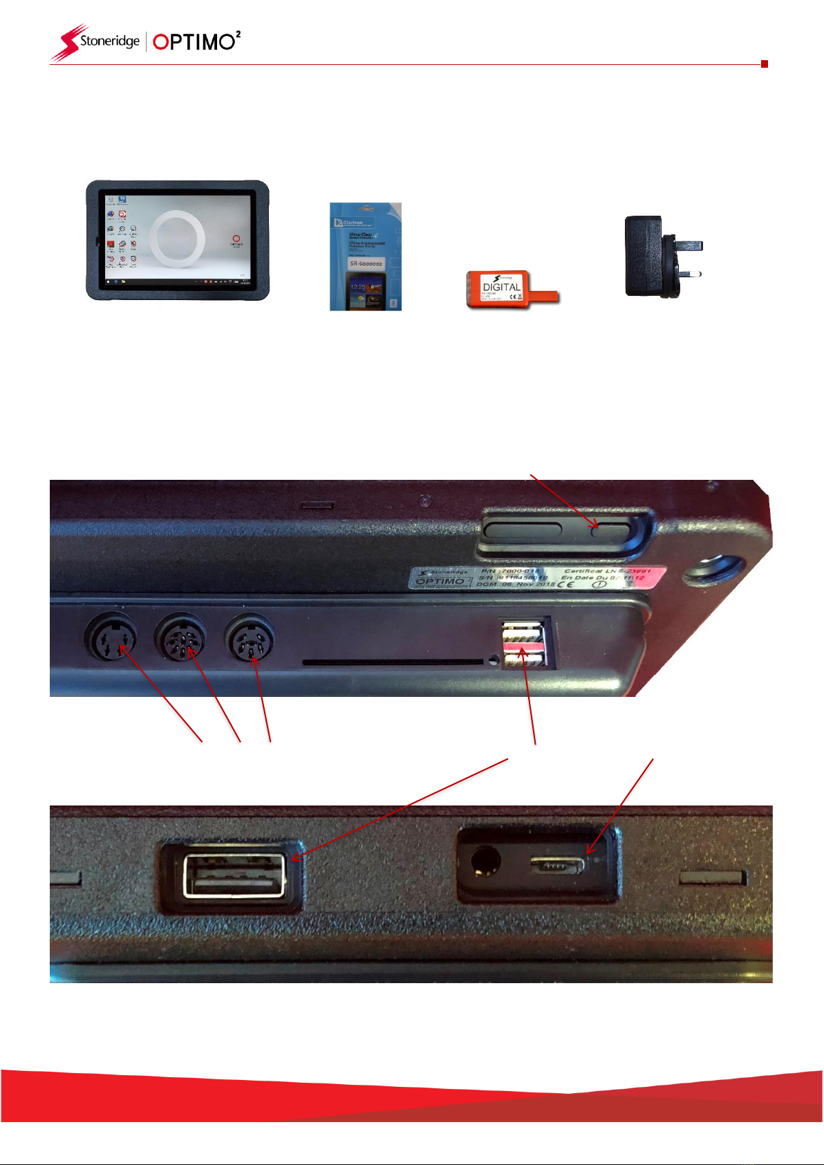
1. Optimo² Kit
Optimo² Screen Protector Digital Dongle
2. Optimo² Switching On
Power on/off
DIN Sockets USB Sockets Power Supply
Notes: Optimo has an in use temperature range of 10°C to 50°C
When charging Optimo, an ambient temperature of +40°C must not be exceeded
PSU/Charger
Cullpower ICP12-050-2000B
Input:100 –240V~ 50/60Hz, 0.3A
Output: 5Vdc, 2000mA

4
3. Optimo² Main Screen
▪Optimo² supports all digital and analogue tachographs.
4. Optimo² Features
Component
Optimo²
External USB ports
3
Bluetooth
Yes
Wi-Fi
Yes
Camera
Yes, Front & Rear
Smart card reader
Yes
Dongles
Digital
I/O connectors
DIN connectors
Battery charge time
4 hours
Vehicle charger
Yes, USB
Screen dimming
Yes
Screen rotation
Yes
Screen protector
Yes

5
5. Optimo² Sleep Mode & Switching Off
5 minutes inactivity
Screen blank –programs still running
Press ON button at rear to wake up
30 minutes inactivity
Optimo² shuts down
Press ON button at rear to re-start
▪To Turn Optimo² Off.
▪Tap Windows Icon in bottom left hand corner of the screen.
▪Tap Power Icon, then Tap Shut down.

6
6. Getting Started
▪How to set up your Optimo².
6.1. Task Bar Icons
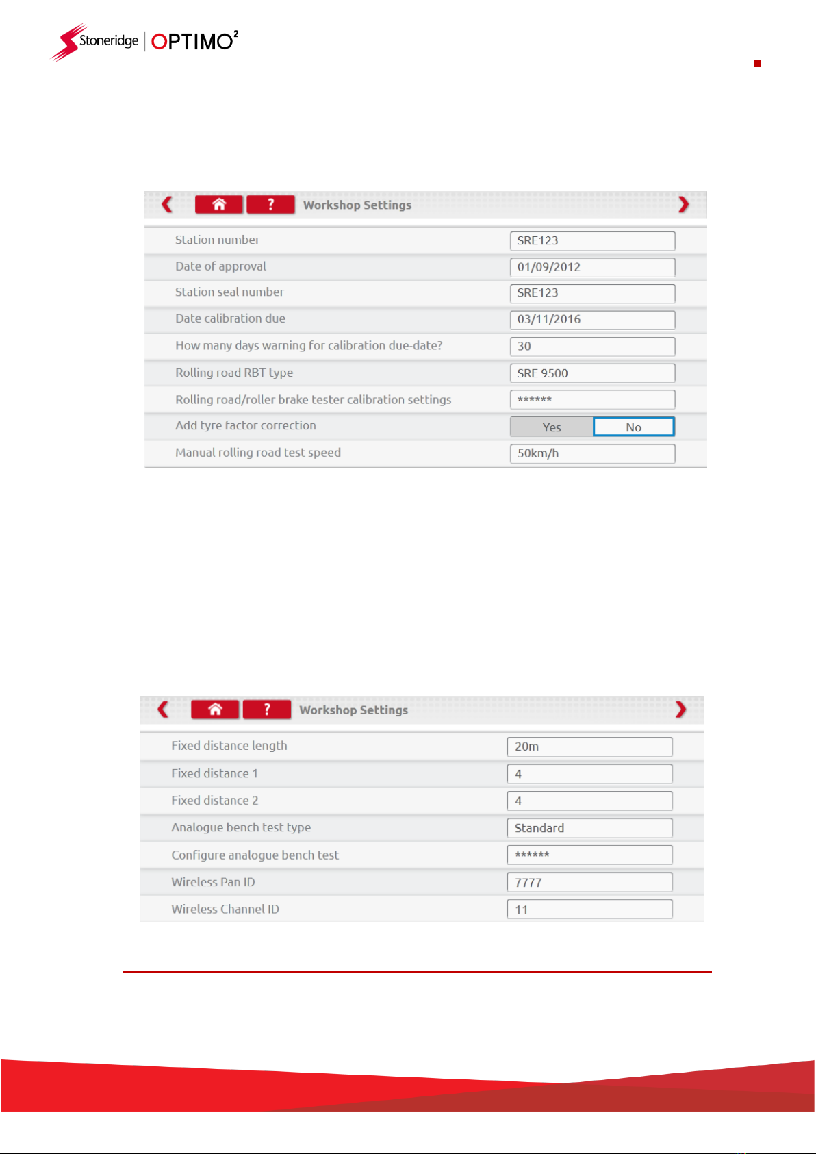
6.1.1. Workshop Settings
▪On first power up of Optimo² several details must be entered into the Workshop Settings screens.
▪Workshop Settings screens can also be accessed at any time by tapping here.
▪After selecting your Language and Country, enter your workshop details.
▪Please complete all fields.
▪Other screens are accessed by tapping the Arrows at the top of the page if highlighted.
Home Button Question Mark
Arrows
▪The ‘Home’ button, single tap, returns to that application’s main screen. A double tap closes the
application and returns to the Windows desktop.
7
▪This screen displays various details about your workshop and enables selection and settings for
Rolling Roads and Roller Brake Testers.
▪Please complete all fields.
▪The next screen sets Fixed distance length and number of runs, plus options for “Standard” or
“Custom” bench tests. For Custom Bench test see Chapter 8.
▪For Pan ID and Channel ID, please refer to your dongle label.
▪Please note that you cannot run two Optimo² with the same ID’s in the workshop.
▪For multiple installation of Optimo² please contact Workshop Support
DETAILS ON ALL THESE SCREENS MUST BE COMPLETED BEFORE FIRST USE OF OPTIMO²

8
6.1.2. Connecting to Wi-Fi
▪Tap the Wi-Fi icon.
▪Select the network and tap “Connect” button.
▪Follow the instructions as requested.
6.1.3. Wireless Connections
▪There are two wireless indicators in the taskbar, one for connection to the tachograph and one
for connection to a Rolling Road. Both are red when disconnected and turn green when
connected.
Tachograph & Rolling Road disconnected
Tachograph connected Rolling Road disconnected

9
6.2. Connecting to the Tachograph
▪3 dongles are supplied for Digital, 2400 and 1324 tachographs. These are inserted into the
programming socket as shown. Please wait 5 seconds after insertion before initiating any
Optimo² applications as this allows time for the tachograph and Optimo² to connect.
▪All tachographs can also be connected using existing MKII cables.
▪Note: 1324 Dongle only on 24V tachographs
6.3. Calibrating and Programming
▪On tapping the icon, Optimo² identifies the connected tachograph. If the tachograph cannot be
determined the screen below is displayed. Select correct tachograph type.
10
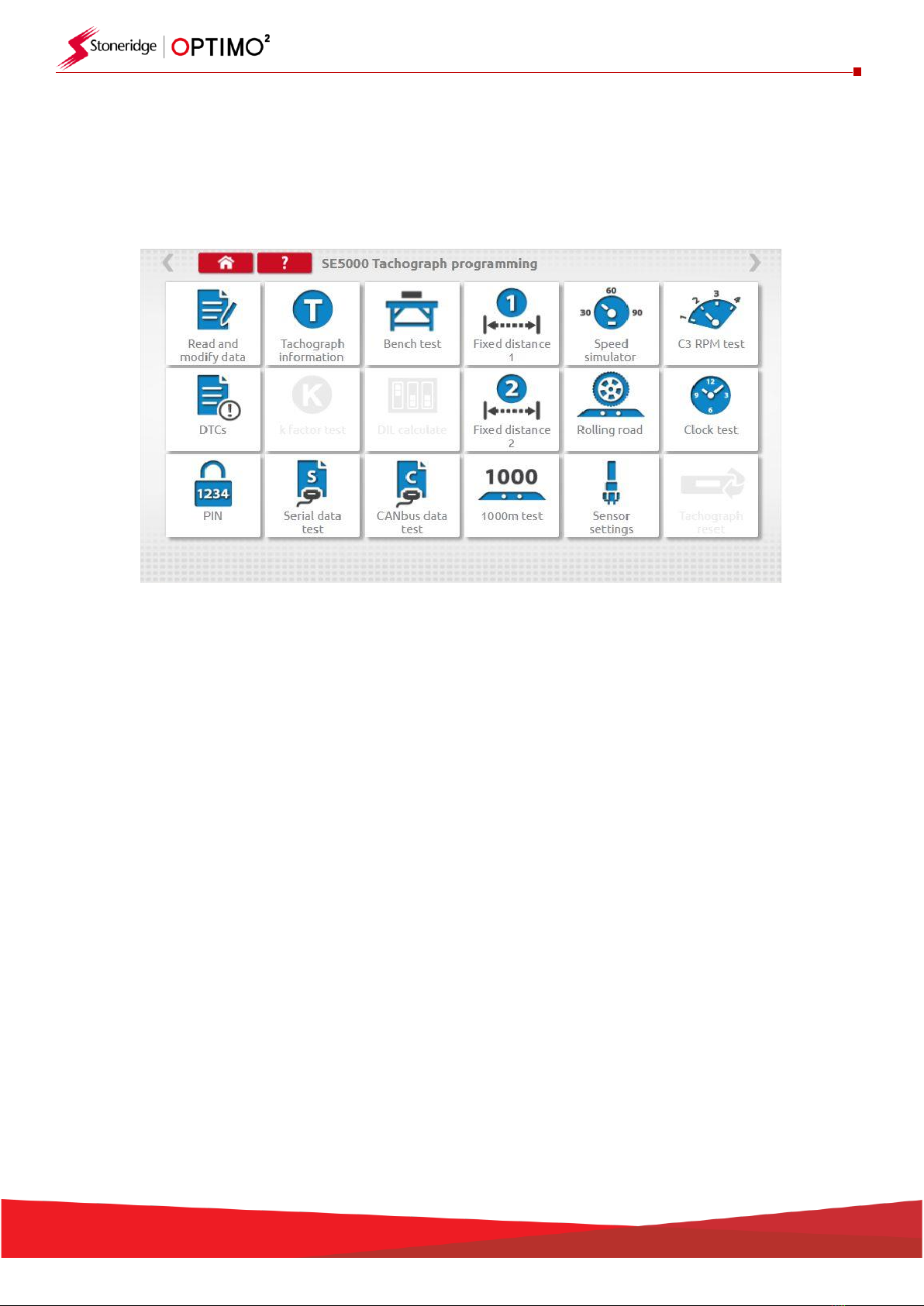
7. Optimo² –MKIII Programmer –Main screens
▪When a tachograph is detected or selected, the screen below is displayed.
▪On these screens highlighted icons can be selected, those dimmed out cannot.
▪The following sub-chapters briefly explain the function for each icon selection.
Read and modify data
Chapter 7.1
Tachograph information
Chapter 7.2
Bench test
Chapter 7.3
Fixed distance 1
Chapter 7.4
Speed simulator
Chapter 7.5
C3 RPM test
Chapter 7.6
DTCs
Chapter 7.7
K factor test
Chapter 7.8
DIL calculate
Chapter 7.9
Fixed distance 2
Chapter 7.10
Rolling road
Chapter 7.11
Clock test
Chapter 7.12
PIN
Chapter 7.13
Serial data test
Chapter 7.14
CANbus data test
Chapter 7.15
1000m test
Chapter 7.16
Sensor settings
Chapter 7.17
Tachograph reset
Chapter 7.18
11
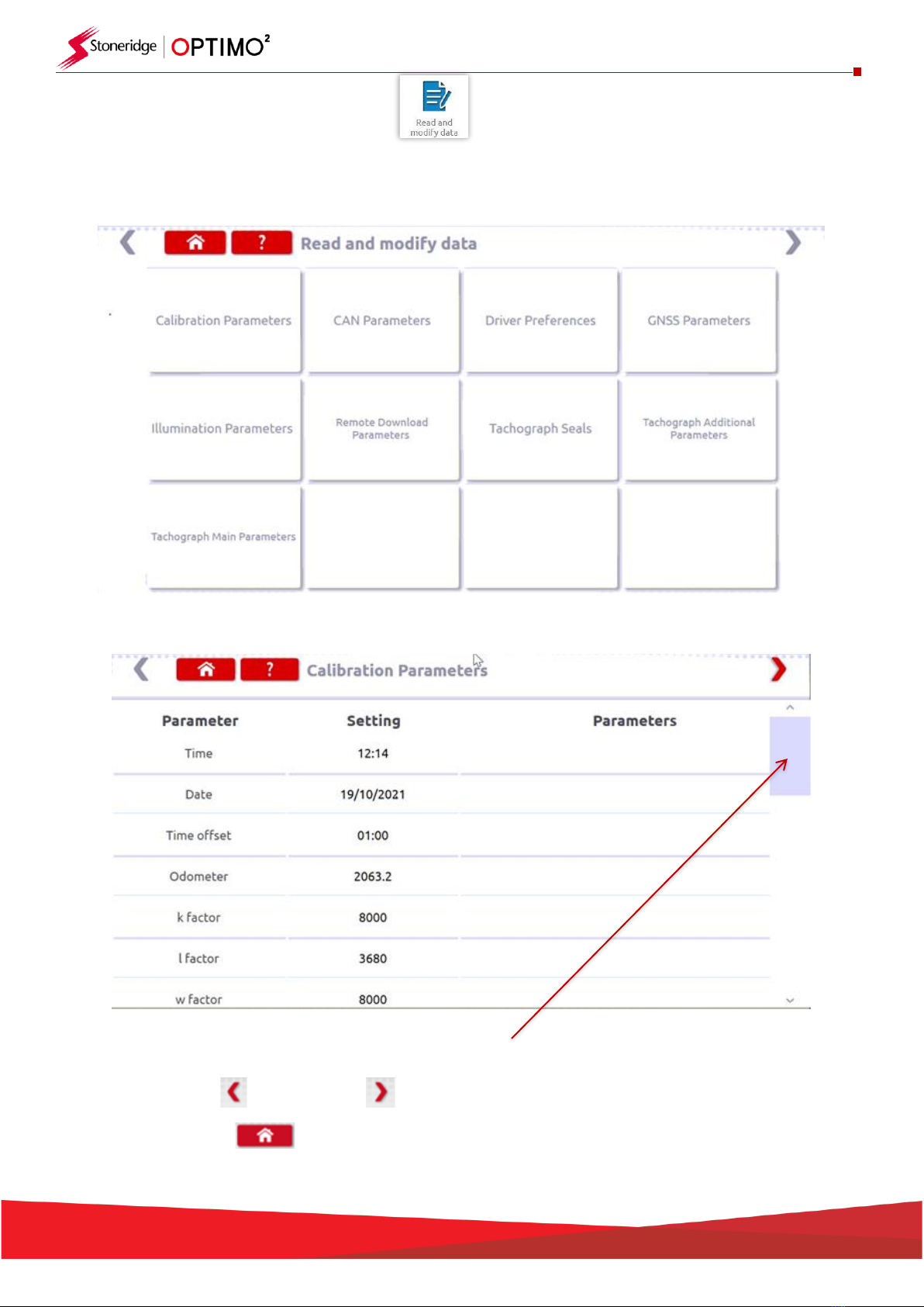
7.1. Read and modify data
▪Select the icon on the tachograph programming screen and this will open the Tiles Menu below
▪Select the Tile you need for specific parameters.
▪Note: A 2 yearly inspection only requires the Calibration Parameters tile
▪Use the scroll bar to view all parameters in the tile
▪
▪Using the left or right arrows moves forwards or backwards through the tiles
▪Press home to return to the Tiles menu
12
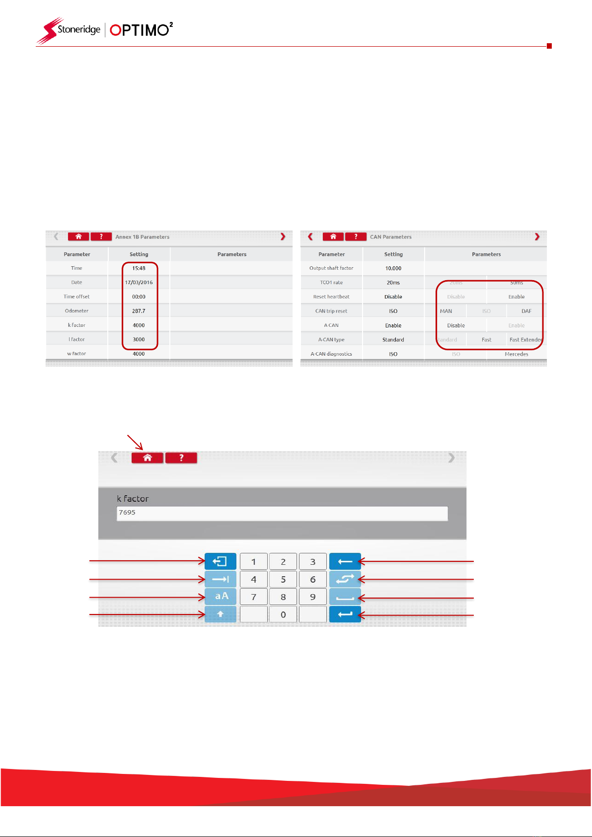
▪Parameters are changed by tapping the value in the “Setting” column and then a new screen is
displayed along with the necessary keyboard, or for some parameters by selecting an appropriate
option from the list available in the Parameters column.
Note 1: In all cases, once settings have been altered, tapping the enter key immediately sends
that information to the tachograph. More screens are accessed by using the highlighted arrows
at the top of the page.
Note 2: For some tachographs, such as the Actia, once a setting has altered it will change colour
to show the setting has been changed but it will not send to the tachograph until you tap the
Home button at the top of the page, whereupon it sends all the data.
▪To change a value, touch the setting on the screen. Use Backspace to remove characters, enter
new value, then tap the Enter key to update the tachograph.
▪Tap the Home button to return to main programming screen.
Backspace
Enter
Keyboard Toggle
Space
Escape
Tab
Caps
Shift

13
7.2. Tachograph Information
▪Tap the icon.
▪Available on all Digital, 2400 or 1324 tachographs.

14
7.3. Bench test
▪Tap the icon.
▪For radio sized tachographs these tests are carried out semi automatically, with a countdown
timer displaying time remaining for each phase of the test.
▪For round tachographs a speed scale must be selected first.
▪For all bench tests follow on screen prompts, and select buttons, duties etc. as required.
Digital Bench test
Analogue Bench test
15
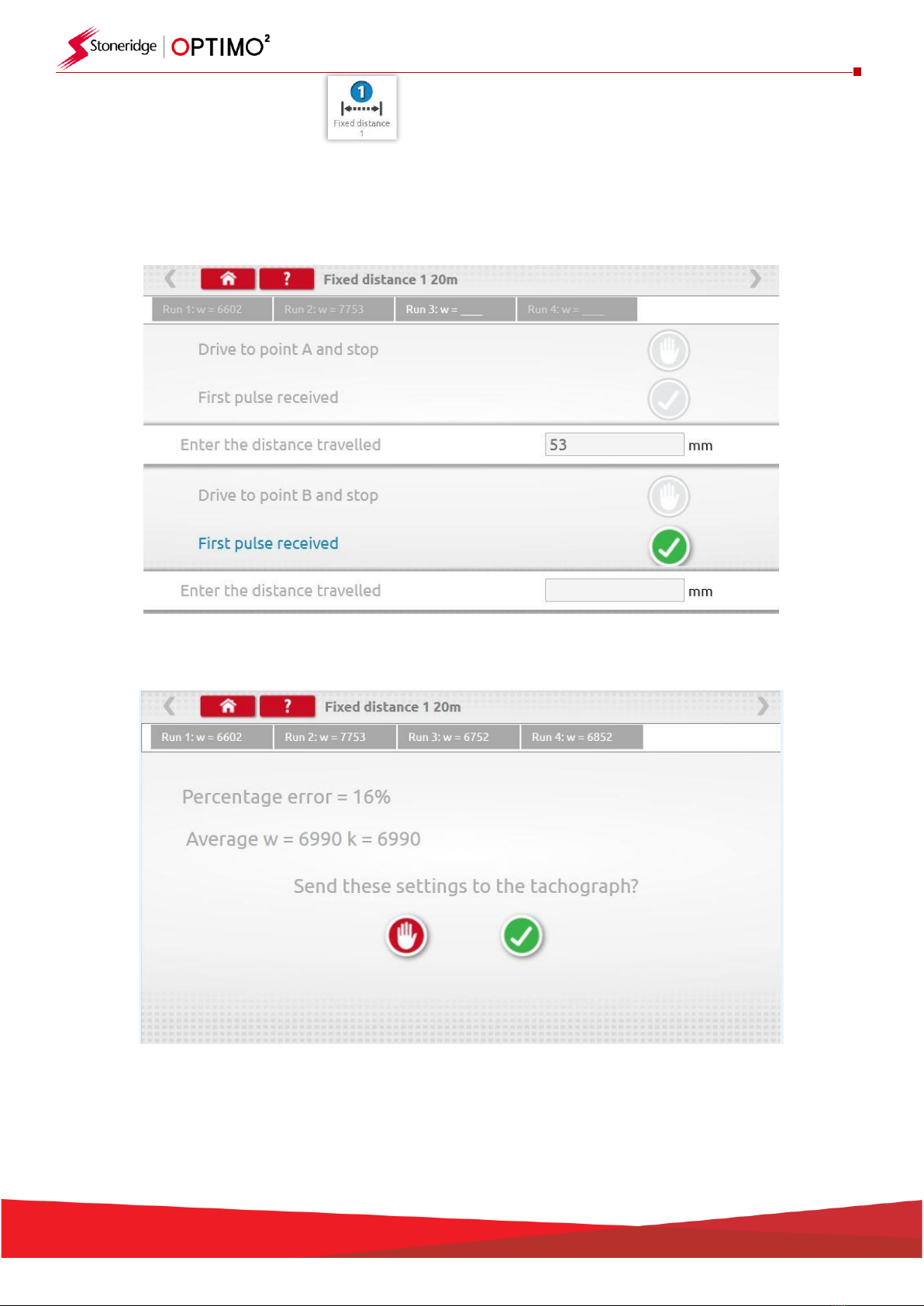
7.4. Fixed distance 1
▪Tapping the icon enables the “w” factor to be determined using a physical method with a fixed
pointer over a fixed distance.
▪The “w” value for each run is displayed. Carry out the appropriate runs as prompted.
▪Test complete
▪For round tachographs, DIL switch settings will be shown which must be manually set.

16
7.5. Speed simulator
▪Tap the icon and then tap “Speed” box and enter the desired speed, then tap the tick button.
7.6. C3 RPM test
▪Connect cable E to Optimo². Tap the icon.
Stop
Test
Increment
Speed
Decrement
Speed

17
7.7. DTCs
▪Tap the icon and the tachograph DTCs are shown.
7.8. k factor test
▪Tap the icon and using cable G on an 8400, 1318 or 1314, it will provide a reading of the k factor
18
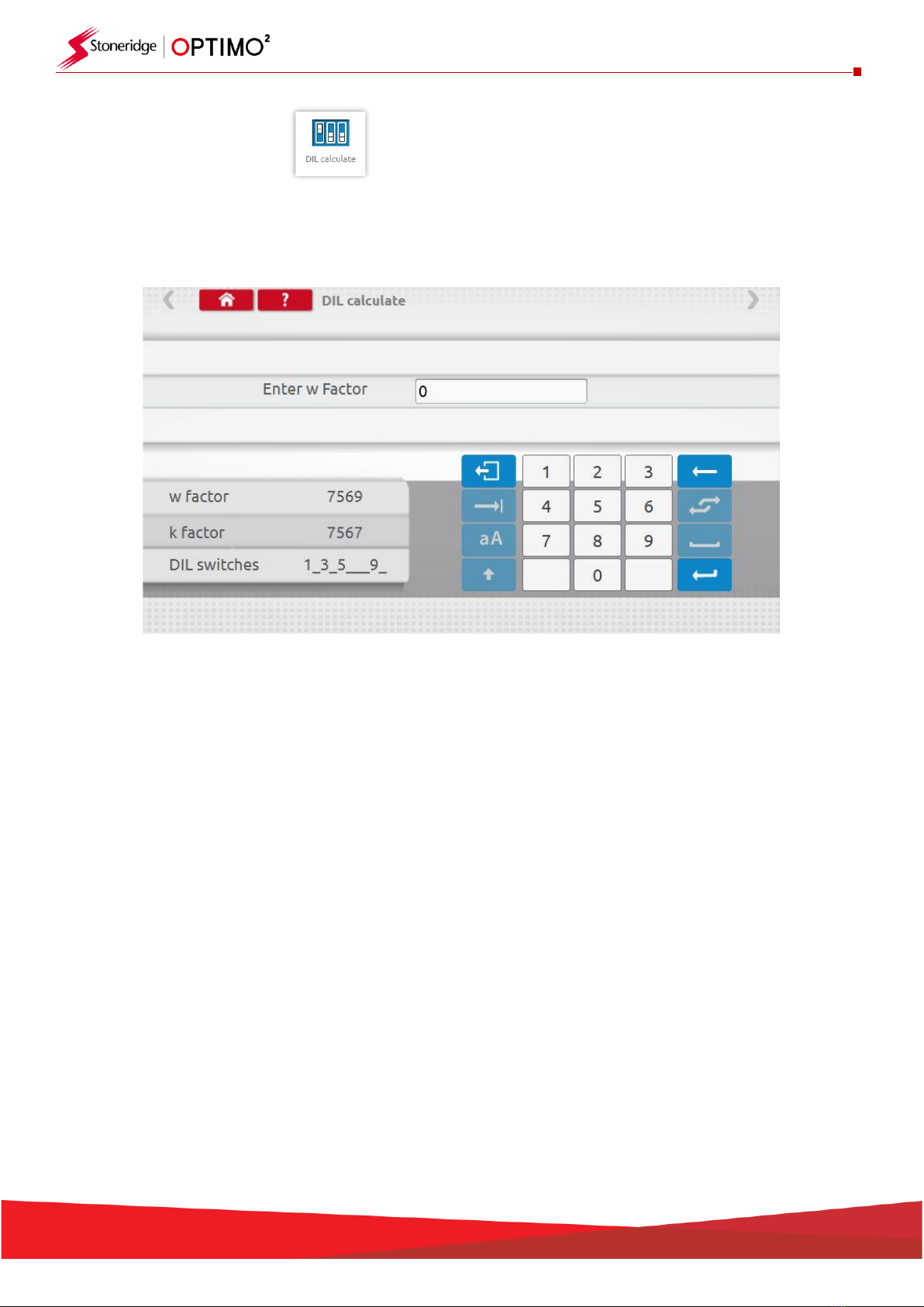
7.9. DIL calculate
▪Tap the icon and enter w factor. DIL switch settings, w factor and k exact are displayed on left.
This function does not require connection to a tachograph.

19
7.10. Fixed distance 2
▪Tapping the icon enables the “w” factor to be determined using a physical method with an
external device such as a flexi switch, light barrier or wireless photocell over a fixed distance.
Connect the external device to Optimo².
▪The “w” value for each run is displayed. Carry out appropriate runs as prompted.
▪Test complete
▪For round tachographs DIL switch settings shown must be manually set.

20
7.11. Rolling road
▪Tapping the icon enables selection of Rolling Road test or Speed Verification test.
▪With vehicle in motion, tap “Speed Verification”, check speed of Rolling Road and compare with
tachograph speed i.e. speed for speed check.
Table of contents


