StorCase Data Silo DS321 User manual

StorCase® Technology
Data Silo®
DS321
External FireWire 800-to-IDE
Expansion Chassis
User's Guide

i
DS321 User's Guide - Rev. B00 StorCase Technolog , Inc.
StorCase® Technology
Data Silo®
DS321
External FireWire 800-to-IDE
Expansion Chassis
StorCase Technology, Inc.
17600 Newhope Street
Fountain Valley, CA 2708- 885
Phone (714) 438-1850 Fax (714) 438-1847
User's Guide
Part No. D89-0000-0213 B00 April 2004

ii
StorCase Technolog , Inc. DS321 User's Guide - Rev. B00
LIMITED WARRANTY
STORCASE TECHNOLOGY, Incorporated (StorCase) warrants that its products will be free
from defects in material and workmanship, subject to the conditions and limitations set forth
below. StorCase will, at its option, either repair or replace an part of its product that proves
defective b reason of improper workmanship or materials. Repair parts or replacement
products will be provided b StorCase on an exchange basis, and will be either new or
reconditioned to be functionall equivalent to new.
This warrant does not cover an product damage that results from accident, abuse, misuse,
natural or personal disaster, external power surge or failure, or an unauthorized disassem-
bl , repair or modification. StorCase will not be responsible for an software, firmware or other
customer data stored within, or interfacing with a StorCase product.
Duration of Warranty
Seven-Year Warranty: The following StorCase products are covered b this warrant for a
period of seven (7) ears from the original date of purchase from StorCase or its authorized
resellers: all Data Express® removable device enclosures and all Data Silo®, Data Stacker® and
InfoStation® external expansion chassis, except for those components integrated into or
purchased separatel for use with these products which are identified and covered b the three-
ear or hard drive warranties described below. All StorCase interface cables and other
accessories specificall intended for use with the StorCase products identified above are also
covered b this (7) ear warrant .
Three-Year Warranty: The following components integrated into or purchased separatel for
use with StorCase Data Express, Data Silo, Data Stacker and/or InfoStation products are subject
to warrant for a period of three (3) ears from the original date of purchase from StorCase or
its authorized resellers: all RAID controllers, power supplies, fans and blowers.
Two-Year Warranty: The following StorCase products are covered b this warrant for a
period of two (2) ears from the original date of purchase from StorCase or its authorized
resellers: all Rhino®JR fixed external expansion chassis (model t pes FJR) and all RhinoJR
removable device enclosures (model t pes RJR).
One-Year Warranty: All StorCase products identified as Reconditioned or Special Inventor
are covered b this warrant for a period of one (1) ear from the original date of purchase from
StorCase or its authorized resellers. Reconditioned products ma onl be exchanged for
reconditioned products.
Hard Disk Drive Warranty: All hard disk drives purchased from StorCase or through its
authorized resellers, whether purchased separatel or integrated into StorCase products,
are subject to the warrant terms and conditions provided b the drive manufacturer.

iii
DS321 User's Guide - Rev. B00 StorCase Technolog , Inc.
Warranty Claim Requirements
To obtain warrant service, the defective product must be returned to our local authorized
StorCase dealer or distributor, or, with prior StorCase approval, to the StorCase factor
service center.
For defective products returned directl to StorCase, a Return Material Authorization (RMA)
number must be obtained b calling StorCase Customer Service at (714) 445-3455. The RMA
number must be prominentl displa ed on the outside of the return package. Shipments must
be freight-prepaid and insured, and must include the product serial number, a detailed
description of the problem experienced, and proof of the original retail purchase date. Products
must be properl packaged to prevent damage in transit. Damage resulting from improper
packaging will not be covered b this warrant . The StorCase factor service center is located
at 17650 Newhope Street, Receiving Dock, Gate #4, Fountain Valle , CA 92780, U.S.A.
Free Technical Support
StorCase provides free technical support. If ou experience an difficult during the
installation or subsequent use of a StorCase product, please contact StorCases Technical
Support Department prior to servicing our s stem. This warrant covers onl repair or
replacement of defective StorCase products, as described above. StorCase is not liable for,
and does not cover under warrant , an costs associated with servicing and/or installation
of StorCase products.
StorCase Technical Support can be reached in the U.S. at (714) 438-1858 or toll-free at (888)
435-5460 (U.S. and Canada onl ). StorCase European Technical Support can be reached in
the U.K. at +44 (0) 1932 738900.
Disclaimers
The foregoing is the complete warranty for the products identified above and
supersedes all other warranties and representations, whether oral or written.
StorCase expressly disclaims all warranties for the identified products, which are
not stated herein, including, to the extent permitted by applicable law, any implied
warranty of merchantability or fitness for a particular purpose. In no event will
StorCase be liable to the purchaser, or to any user of a StorCase product, for any
damages, expenses, lost revenues, lost savings, lost profits, or any other
incidental or consequential damages arising from the purchase, use or inability
to use a StorCase product, even if StorCase has been advised of the possibility
of such damages.
Cop right © 2004 StorCase Technolog . All rights reserved. All registered
trademarks are the propert of StorCase Technolog . All other logos and trademarks
are properties of their respective companies.

iv
StorCase Technolog , Inc. DS321 User's Guide - Rev. B00
Company Name:
Corporate Office Address:
Manufacturing Address:
Product Name:
Model Number:
Conforms to the following standards:
EMC Directives:
(8 /336/EEC)
Low Voltage Directive:
(73/23/EEC)
Safety Standards:
CSA (NRTL/C)
TUV:
EMI Standards:
EMC Standards:
Year of Manufacture:
Signature:___________________
Full name: Dieter Paul
Position: President
StorCase Technolog , Inc.
17600 Newhope Street
Fountain Valle , CA 92708
17600 Newhope Street
Fountain Valle , CA 92708
Data Silo DS321
S30F107
ITE Emission
- EN 55022: 1998
- EN 61000-3-2 Harmonic Current
- EN 61000-3-3 Voltage Fluctuations and Flicker
EN 55024: 1998 ITE Immunit
- IEC 61000-4-2 - IEC 61000-4-5
- IEC 61000-4-3 - IEC 61000-4-6
- IEC 61000-4-4 - IEC 61000-4-8
- IEC 61000-4-11
EN 60950
CAN/CSA-C22.2 No. 950-95
UL 1950, Third Edition
EN 60950: 1992 + A1 + A2 + A3 + A4 + A11
FCC Part 15, Class A
AS/NSZ 3548 Information Technolog Equipment
2004
Declaration of Conformity

v
DS321 User's Guide - Rev. B00 StorCase Technolog , Inc.
Important Safety Instructions
1. Read all these instructions.
2. Save these instructions for later use.
3. Follow all warnings and instructions marked on the product.
4. Do not use this product near water.
5. This product should be operated from the t pe of power source indicated on the
marking label. If ou are not sure of the t pe of power available, consult our dealer
or local power compan .
6. Do not attempt to service this product ourself, as opening or removing covers ma
expose ou to dangerous voltage points or other risk. Refer all servicing to service
personnel.
Wichtige Sicherheitshinweise
1. Diese Hinweise sollten vollständig durchgelesen werden.
2. Diese Hinweise für einen späteren Gebrauch aufbewahren.
3. Allen auf dem Gerät angebrachten Warnungen und Hinweisen folgen.
4. Das Gerät nicht in der Nähe von Wasser verwenden.
5. Das Gerät nur mit dem Aufkleber bezeichneten Netzspannung betreiben. Bei
Fragen über die Art der Netzspannung sollte der Händler oder das
Energieversorgungsunternehmen zu rate gezogen werden.
6. Nicht versuchen das Produkt selbst zu reparieren. In allen Produkten existieren
gefährliche elektrische Spannugen. Nicht das Gehäuse öffnen.
7. Wartungsarbeiten nur von qualifiziertern Kundendienstpersonal ausführen
laßen.

vi
StorCase Technolog , Inc. DS321 User's Guide - Rev. B00
Table of Contents
INTRODUCTION ..................................................................................................................... 1
Packaging Information .................................................................................................. 1
Serial Number ................................................................................................................ 1
General Description ...................................................................................................... 2
Front Panel ............................................................................................................ 4
Rear Panel ............................................................................................................. 6
INSTALLATION ...................................................................................................................... 7
Drive Preparation .......................................................................................................... 7
Drive Installation ................................................................................................... 8
Desktop Conversion ................................................................................................... 10
Rack Mount Conversion ............................................................................................. 11
T pical FireWire Configurations ................................................................................. 12
T pical Single Host Configurations ................................................................... 12
T pical Dual Host Configurations ...................................................................... 14
APPENDICES ........................................................................................................................ 17
Appendix A - Specifications/Dimensions .................................................................. 18
Appendix B - Optional Accessories .......................................................................... 20
FireWire Cables .................................................................................................. 20
Removable Drive Carriers .................................................................................. 21
Carr ing Case ..................................................................................................... 22
Reader's Comments ............................................................................................................ 23

vii
DS321 User's Guide - Rev. B00 StorCase Technolog , Inc.
NOTICE: This User's Guide is subject to periodic updates without notice. While reason-
able efforts have been made to ensure accurac of this document, StorCase
Technolog , Inc. assumes no liabilit resulting from errors or omissions in this
publication, or from the use of the information contained herein.
Please check the StorCase web site at http://www.storcase.com or contact
our StorCase representative for the latest revision of this document.
List o Figures
Figure 1: Data Silo DS321 .............................................................................................. 2
Figure 2: Front Panel ...................................................................................................... 5
Figure 3: Rear Panel ...................................................................................................... 6
Figure 4: Drive Installation Assembl ............................................................................ 8
Figure 5: Drive Cover Installation .................................................................................. 9
Figure 6: Desktop Conversion ..................................................................................... 10
Figure 7: Rack Mount Conversion ............................................................................... 11
Figure 8: T pical Single Host Connection to One Data Silo ....................................... 12
Figure 9: T pical Single Host Connection to Multiple Data Silos ................................ 13
Figure 10: T pical Dual Host Connection to One Data Silo .......................................... 14
Figure 11: T pical Dual Host Connection to Multiple Data Silos .................................. 15
Figure A-1: DS321 Ph sical Dimensions ........................................................................ 19
Figure B-1: FireWire Cables ............................................................................................ 20
Figure B-3: DE110 Drive Carrier ..................................................................................... 21
Figure B-4: Carr ing Case ............................................................................................... 22

Introduction 1
DS321 User's Guide - Rev. B00 StorCase Technolog , Inc.
INTRODUCTION
PackagingIn ormation
The StorCase Technolog Data Silo® external expansion chassis is shipped in a container
designed to provide protection and prevent damage during shipment. The Data Silo was
carefull inspected before and during the packing procedure at the factor . Evidence of an
damage to the Data Silo should be reported to the shipper immediatel .
If the wrong Data Silo model has been received, please call our reseller or StorCase at
(800) 435-0642 to arrange for a Return Material Authorization (RMA). StorCase cannot ac-
cept returns which do not displa an RMA number on the outside of the package. Return the
unit with all the original packing materials.
Before removing an component from its packaging, discharge an static electricit b
touching a properl grounded metal object.
Serial Number
The Data Silo is labeled with a serial number. This number must be reported to the StorCase
Customer Service Representative in order to receive a Return Material Authorization (RMA)
for warrant claims. Locate the serial number label and record the number in the space
provided below.
Serial Number:
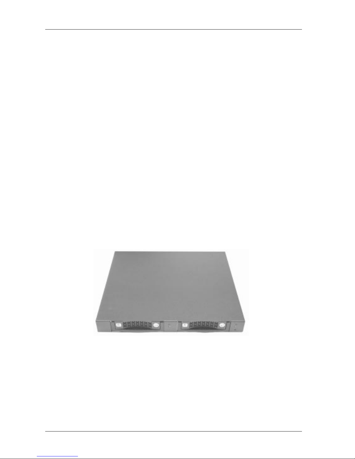
2Introduction
StorCase Technolog , Inc. DS321 User's Guide - Rev. B00
Figure 1: Data Silo DS321
General Description
WARNING: The DS321 contains NO USER SERVICEABLE PARTS inside the unit. Refer ALL
servicing to qualified service personnel!
The StorCase Technolog Data Silo® DS321 2-ba expansion chassis with FireWire 800
(IEEE-1394b) interface provide durable and reliable mounting for two (2) 3.5" form factor, low-
profile (1" high) Ultra ATA100 or 133 drives. It is downward compatible with earlier technolog
IDE drives.
The DS321 is a 1U desktop (rack-mountable with provided hardware), dual ba configuration
(Figure 1) for removable drives (equipped with 2 Data Express® DE110 removable drive
enclosures). Each chassis is constructed of rugged steel and is equipped with one (1) 40W
auto-switching power suppl , drive status LEDs, one (1) cooling fan (5.5 CFM), and all
necessar internal wiring and drive mounting hardware.
The DS321 comes standard with two (2) dual port FireWire 800 (IEEE-1394b) interfaces, which
allow for single or dual host configurabilit .
321_01
Table of contents


