StorCentric Nexsan E48X Parts list manual

Copyright © 2010–2022 Nexsan. All Rights Reserved Worldwide. www.nexsan.com
Trademarks
Nexsan®, BEAST™, BEAST P™, BEAST Elite™, BEAST X™, Nexsan E60™, Nexsan E60V™, Nexsan E60VT™, Nexsan E60P™, Nexsan
E60X™, Nexsan E48™, NexsanE48V™, Nexsan E48P™, Nexsan E48VT™, Nexsan E48X™, Nexsan E32F™, Nexsan E32V™, Nexsan
E32X™, Nexsan E18™, Nexsan E18P™, Nexsan E18F™, Nexsan E18V™, Nexsan E18X™, and the Nexsan logo are trademarks or registered
trademarks of Nexsan.
All other trademarks and registered trademarks are the property of their respective owners.
Patents
This product is protected by one or more of the following patents, and other pending patent applications worldwide:
United States patents US8,191,841, US8,120,922
United Kingdom patents GB2296798B, GB2297636B, GB2466535B, GB2467622B, GB2467404B
Regulatory compliance
United States Statement for FCC: This equipment has been tested and found to comply with the limits for a Class A digital device, pursuant to
Part 15 of the FCC Rules. These limits are designed to provide reasonable protection against harmful interference when the equipment is
operated in a commercial environment. This equipment generates, uses, and can radiate radio frequency energy and, if not installed and used in
accordance with the instruction manual, may cause harmful interference to radio communications. Operation of this equipment in a residential
area is likely to cause harmful interference in which case the user will be required to correct the interference at his own expense.
Electromagnetic Emissions: FCC Class A, EN 55022 Class A, EN 61000-3-2/-3-3, CISPR 22 Class A
Electromagnetic Immunity: EN 55024/CISPR 24, (EN 61000-4-2, EN 61000-4-3, EN 61000-4-4, EN 61000-4-5, EN 61000-4-6, EN 61000-4-8,
EN 61000-4-11)
Safety: CSA/EN/IEC/UL 60950-1 Compliant, UL or CSA Listed (USA and Canada), CE Marking (Europe)
California Best Management Practices Regulations for Perchlorate Materials: This Perchlorate warning applies only to products containing CR
(Manganese Dioxide) Lithium coin cells. Perchlorate Material-special handling may apply. See www.dtsc.ca.gov/hazardouswaste/perchlorate.
Use and limitations of this document
Unauthorized use, duplication, or modification of this document in whole or in part without the written consent of Nexsan is strictly prohibited.
Nexsan reserves the right to make changes to this manual, as well as the equipment and software described in this manual, at any time without
notice. This manual may contain links to Web sites that were current at the time of publication, but have since been moved or become inactive. It
may also contain links to sites owned and operated by third parties. Nexsan is not responsible for the content of any such third-party site.

About this manual v
Conventions v
Notes, tips, cautions, and warnings v
Contacting Nexsan vi
Service and support vi
Related documents vi
Safety notices vi
Revision history vii
Chapter 1: Overview 1
Front panel 2
Legend 2
Rear panel 4
Legend 4
Drawer interior 6
Legend 6
Physical characteristics 8
Dimensions, Nexsan E48X 8
Dimensions, Nexsan E60X 8
Power 9
Cooling 9
Materials 9
Environment 9
Chapter 2: Adding Modules 11
Take proper ESDprecautions 12
Adding disk drives 13
Chapter 3: Replacing Modules 15
Power Supply Units (PSUs) 16
Expansion Controllers 17
Disk drives 19
Front drive drawer fans 22
Rear drive drawer fan assembly 24
Contents
Nexsan E48X and Nexsan E60X
FRU Removal and Replacement Guide
Nexsan
www.nexsan.com
iii

About this manual
This FRU removal and replacement guide provides detailed procedures for installing, removing, and
replacing field-replaceable units (FRUs) in Nexsan E48X Storage Expansions.
Note While Nexsan makes every effort to ensure the accuracy of technical documentation, screen images
and procedures may change after publication. In case of discrepancy, please check for the latest updates
on the E-Series and BEAST Documents and Downloads page. Also, refer to the latest Release Notes.
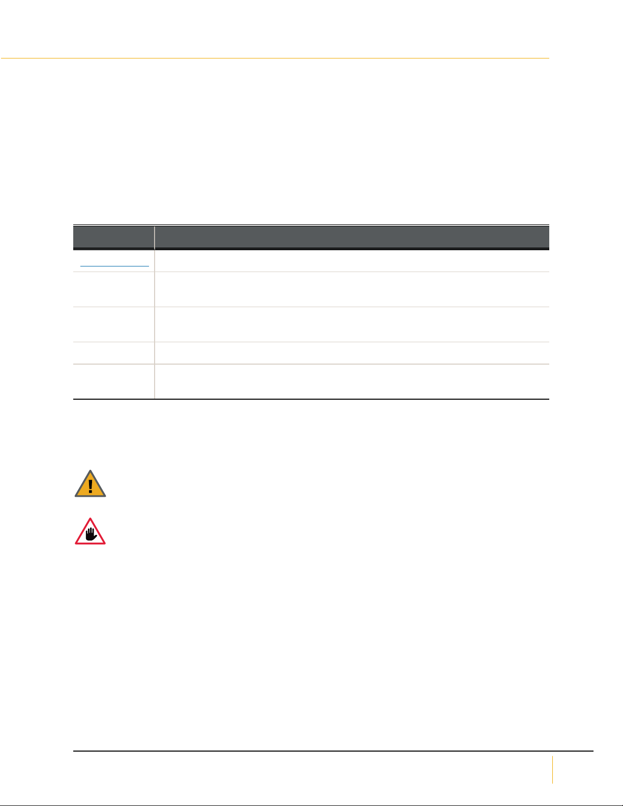
Conventions
Here is a list of text conventions used in this document:
Convention Description
underlined blue Cross-references, hyperlinks, URLs, and email addresses.
boldface Labels on the physical Nexsan Storage System or interactive items in the graphical
user interface (GUI).
italics System messages and non-interactive items in the GUI. References to software user
guides.
monospace Command-line interface (CLI) text or text that refers to file or directory names.
monospace
bold
Text strings that must be entered by the user in the CLI or in text fields in the GUI.
Notes, tips, cautions, and warnings
Note Notes contain important information, present alternative procedures, or call attention to certain items.
Tip Tips contain handy information for end-users, such as other ways to perform an action.
CAUTION: In hardware manuals, cautions alert the user to items or situations which may cause
damage to the Nexsan Storage System or result in mild injury to the user, or both. In software
manuals, cautions alerts the user to situations which may cause data corruption or data loss.
WARNING: Warnings alert the user to items or situations which may result in severe
injury or death to the user.
About this manual
Nexsan E48X and Nexsan E60X
FRU Removal and Replacement Guide
Nexsan
www.nexsan.com
v

Contacting Nexsan
For questions about Nexsan products, please visit the Nexsan support Web page, and the E-Series and
BEAST Documents and Downloads page. If you are unable to find the answer to your question there,
please see our contact information below.
Service and support
Nexsan's Technical Services Group provides worldwide assistance with installation, configuration, software
support, warranty, and repair for all Nexsan products. A variety of service and support programs are
available to provide you with the level of coverage and availability your operation requires.
Nexsan Headquarters
1289 Anvilwood Avenue
Sunnyvale, CA 94089
United States of America
Worldwide Web site
www.nexsan.com
E-Series and BEAST support:
https://helper.nexsansupport.com/esr_support
European Head Office, UK
Units 33–35 Parker Centre
Mansfield Road
Derby, DE21 4SZ
United Kingdom
Contact:
https://helper.nexsansupport.com/contact
Related documents
The following Nexsan product manuals contain related information:
Nexsan E48 and Nexsan E60 Storage Systems FRU Removal and Replacement Guide
Nexsan E48 and Nexsan E60 Storage Systems Installation Guide
Nexsan E48X and Nexsan E60X Storage Systems Installation Guide
Nexsan High-Density Storage User Guide
Nexsan E-Series Snapshots and Replication User Guide
Nexsan E-Series Multipathing Best Practices Guide
Safety notices
This guide covers the Nexsan E60X and Nexsan E48X Storage SystemsStorage Expansions only. Refer to
the relevant product manuals for information on other Nexsan Storage Systems or Storage Expansions and
other Nexsan products mentioned in this guide.
Always observe the following precautions to reduce the risk of injury and equipment damage:
WARNING: There is a risk of ELECTRIC SHOCK if Nexsan E-Series components are removed or
tampered with when a Nexsan Storage System power is on. Only a trained operator may remove
certain FRUs. The Nexsan E-Series Storage Systems include the following FRUs:
Power Supply modules
RAID Controller and Expansion modules
Disk drives
Fan modules
About this manual
vi Part Number: P0450141, Rev. B
www.nexsan.com
Nexsan BEAST™ and E-Series™

The storage system should only be installed in a clean, dry environment. The operating temperature is 5º
to 35º C (41º to 95º F), with operating relative humidity at 20 to 80%, non-condensing.
The cordset specification for the Nexsan E60X and Nexsan E48X in North America is USA IEC C13 to
IEC C14, rated 250V/10A. When applying power to the storage system, use ONLY the IEC power cords
originally supplied with it. Do NOT use other power cords, even if they appear identical to the supplied
cords.
Only a fully-trained Service Engineer is authorized to disassemble any other part of the storage system,
and then only when the storage system is powered off.
All Nexsan E-Series Storage Systems have multiple power connections; as a result, you must remove all
power leads to completely remove power from the storage system.
Revision history
This section lists updates and new material added to the Nexsan E-SeriesFRU Removal and Replacement
Guide for the Nexsan E60X and Nexsan E48X Storage Systems.
P450135 Rev: B, March 2022
Updated for technical accuracy, applied new Nexsan template and branding.
P0450141, Rev A, August 2016
Changed document number to part number
Added Information for E60P and E48P
NXS-EX4U-MG Rev. 03, October 2014
Added section Take proper ESDprecautions on page12 to the beginning of Chapter 2; updated all
ESDwarnings; added ESD warnings to all sections that deal with handling electronic components or disk
drives, each one referencing Take proper ESDprecautions on page12.
NXS-EX4U-MG Rev. 02, July 2014
Fixed minor errors throughout.
NXS-EX4U-MG Rev. 01, February 2014
Changed formatting throughout to reflect Nexsan as an Nexsan brand; separated installation content from
FRUreplacement content into two documents; changed name of document to Nexsan E-Series FRU
Removal and Replacement Guide for the Nexsan E60X and Nexsan E48X RAIDStorage Expansion Units.
About this manual
Nexsan E48X and Nexsan E60X
FRU Removal and Replacement Guide
Nexsan
www.nexsan.com
vii

Chapter 1
Chapter 1:Overview
Nexsan E48X and Nexsan E60X 4U, rack-mountable Storage Expansions can hold up to 48 or 60 SATA,
SAS, or SSD data disks respectively.
Nexsan E-Series base models use 3Gb/s SAS for internal communication between the RAID Controllers
and hard disks. E-Series P models use 6-Gb/s SAS for internal communication.
This chapter contains the following sections:
Front panel 2
Rear panel 4
Drawer interior 6
Physical characteristics 8
Nexsan E48X and Nexsan E60X
FRU Removal and Replacement Guide
Nexsan
www.nexsan.com
1
1

Front panel
Use this section to understand front panel components.
Figure 1-1: Nexsan E48X/Nexsan E60X front panel
Legend
Use the following tables as a legend for the front panel diagram.
Table 1-2: Field-replaceable modules
Number Component Description
1. Drawer Front
Assembly w/
Fan
Each assembly can be field-replaced in the event of a fan failure by
removing a screw on each side of the drive drawer (see Front drive drawer
fans on page22).
Table 1-3: Other modules
Number Component Description
2. Active Drive
Drawers (3)
Each drawer can hold up to 16 (for Nexsan E48X Storage Expansions) or
20 (for Nexsan E60X Storage Expansions) 3.5" disk drives, for a total of up
to 48 or 60 drives in the enclosure.
Front panel
2 Part Number: P0450141, Rev. B
www.nexsan.com
Nexsan BEAST™ and E-Series™
1

Table 1-4: LEDs
Number Component Description
3. Power LED(PWR) Indicates the status of power to the components in the drawer.
Green indicates that all power levels are within specifications. Red
indicates that one or more power levels are outside of
specifications. The Environmental Information page (under
System Information) in the graphical user interface (GUI) displays
details (see the Nexsan High-Density Storage User Guide).
If the PWR LED on the left drive drawer is amber and all other front
panel LEDs are off, this means that the Nexsan Storage System
has been powered down through the GUI. It can be powered back
up using the SW0 switch (see Rear panel on the next page).
4. Disk LED (DSK) Indicates the status of the disk drives in the drawer. Green indic-
ates that all disk drives are operating within specifications. Red
indicates that one or more disk faults have been detected. The
Disk Drives page (under RAID Information) in the graphical user
interface (GUI) displays details (see the Nexsan High-Density Stor-
age User Guide).
5. Environment LED
(ENV)
Indicates the temperature and fan status for the drawer. Green
indicates that the drawer temperature is within specifications and
that all fans are operating properly. Red indicates that the
temperature exceeds specifications or that one or more fans are
not operating properly. The Environmental Information page
(under System Information) in the graphical user interface (GUI)
displays details (see the Nexsan High-Density Storage User
Guide).
6. Status LED (STAT) Indicates overall status. Green indicates that the Nexsan Storage
System is operating within specification. Amber indicates that the
drawer is unlocked. Red indicates a fault in the drawer.
If all STAT LEDs are red, this indicates that there is an issue with
the Nexsan Storage System that is not drawer-specific. The
Environmental Information page (under System Information) in
the graphical user interface) displays details (see the Nexsan
High-Density Storage User Guide).
Table 1-5: Other items
Number Component Description
7. Drawer Lock: Secures the drive drawer in place. When this lock is disengaged, the STAT
LED turns amber.
Chapter 1: Overview
Nexsan E48X and Nexsan E60X
FRU Removal and Replacement Guide
Nexsan
www.nexsan.com
3
1

Rear panel
Use this section as a legend for rear panel components.
Figure 1-6: Nexsan E48X/Nexsan E60X rear panel
EXP 0 EXP 1
L1 STATL0
EXP 0 EXP 1
L1L0
EXP 0 EXP 1
L1 STATL0
EXP 0 EXP 1
L1L0
WARRANY VOID
IF SEAL BROKEN
WARRANY VOID
IF SEAL BROKEN
1a1b
2a2b
33 3
54
8
679
8
Field Replaceable Modules:
1a. Expansion Controller 0
1b. Expansion Controller 1
2a. Power Supply Unit (PSU) 0
2b. Power Supply Unit (PSU) 1
Other Modules:
3. Interconnect Service Modules (ISMs)
Connectors:
4. Power
5. Expansion
LEDs:
6. PSU status
7. PSU Fan status
8. Expansion Port status
9. Expansion Controller status
Legend
Use the following tables as a legend for the rear panel diagram.
Table 1-7: Field-replaceable modules
Number Component Description
1. RAID Controller(s)
(1 or 2)
Expansion Controllers (2). Each controller can be field-replaced in
the event of failure (see Expansion Controllers on page17).
2. Power Supply
Units (PSUs) (2)
Each controller can be field-replaced in the event of a PSU or PSU
fan failure (see Power Supply Units (PSUs) on page16).
Table 1-8: Other modules
Number Component Description
3. Interconnect Service Modules (ISMs)
(3)
Can only be replaced by a fully-trained Service
Engineer.
Rear panel
4 Part Number: P0450141, Rev. B
www.nexsan.com
Nexsan BEAST™ and E-Series™
1

Table 1-9: Connectors
Number Component Description
4. Power (2): 200–240VAC, 47–63Hz
(for Nexsan E60X Storage
Expansions) or 110–240VAC, 47–
63Hz (for Nexsan E48X Storage
Expansions).
CAUTION: The cordset specification for
the Nexsan E60Nexsan E60X/Nexsan
E48X in North America is IEC C13 to IEC
C14 rated 250V/10A. When applying
power to the system, use ONLY the IEC
power cords originally supplied with the
Nexsan Storage System. Do NOT use
other power cords, even if they appear
identical to the supplied cords.
5. E-Series V/VT Four expansion ports (EXP IN 0 and 1,EXP OUT 0
and 1) per Expansion Controller: Mini-SAS 26 pin I-
Pass (8088) 6Gb/s SAS connectors.
6. One Management port (MGMT)
per RAID Controller
Dedicated management port (RJ45) for Web-based
configuration (1Gb in E-Series P, 10/100 in prior
series models).
7. One SERIAL port per RAID
Controller
Mini-DIN serial port for low-level reporting (Support
use only).
8. Four iSCSI ports (0through 3) per
RAID Controller
1Gb/s Ethernet ports (RJ45s) for iSCSI. If a host
port option is installed (see Rear panel on the
previous page), only ports 0and 1are usable.
9. Host ports See Rear panel on the previous page.
Table 1-10: LEDs
Number Component Description
12. Expansion port LEDs
Chapter 1: Overview
Nexsan E48X and Nexsan E60X
FRU Removal and Replacement Guide
Nexsan
www.nexsan.com
5
1

Drawer interior
Use this section to understand Drawer interior components.
Figure 1-11: Nexsan E60X drawer interior
1
2
3
4
1. Disk Drives
2. Rear Fan Assembly
3. Drive Rails
4. Drive Status LEDs
Figure 1-12: Nexsan E48X drawer interior
1
2
3
4
1. Disk Drives
2. Rear Fan Assembly
3. Drive Rails
4. Drive Status LEDs
Legend
Use the following tables as a legend for the Drawer interior components diagram.
Table 1-13: Field-replaceable modules
Number Module Description
1. Disk Drives Up to 16 (for Nexsan E48X Storage Systems) or 20 (for Nexsan E60X
Storage Systems) 3.5" disk drives in each drawer. Disk drives can be field-
replaced in the event of failure (see Disk drives on page19).
2. Rear Fan
Assembly
Dual-fan assembly located at the rear of each drawer. Can be field-replaced
in the event of failure (see Rear drive drawer fan assembly on page24).
Drawer interior
6 Part Number: P0450141, Rev. B
www.nexsan.com
Nexsan BEAST™ and E-Series™
1

Table 1-14: Other modules
Number Module Description
3. Drive
Guides
Align with plastic rails on disk drives to guide installation. These are integral to
the drive drawer and cannot be individually replaced.
Table 1-15: LEDs
Number Module Description
4. Drive
status
One for each disk drive slot. Solid green indicates that the disk is operating
within specifications and is not currently being accessed. Flashing green
indicates disk activity. Red indicates that a disk fault has been detected and
that the disk is not currently being used by the system. For disk drive slots
where no disk drive is installed, this LED is off.
Chapter 1: Overview
Nexsan E48X and Nexsan E60X
FRU Removal and Replacement Guide
Nexsan
www.nexsan.com
7
1

Physical characteristics
Use this section as a reference for the physical characteristics of Nexsan Storage Systems or Nexsan
Storage Expansions.
Dimensions, Nexsan E48X
Measurement Value
Chassis height 4U: 177mm (6.97")
Chassis length 835mm (32.87")
Chassis length, including
fascia and handles
887mm (35.95")
(allow at least 150mm for cables at rear; a 1,000mm rack is recommended)
Chassis width, body 448mm (17.64")
Chassis width, overall 482.6mm (19")
Storage System weight, no
drives
47.63 kg (105 lbs.)
Storage System weight,
with drives
84 kg (185.2 lbs.)
Rack mount kit length 660mm to 914mm (26" to 36")
Rack mount kit weight approx. 2.5 kg (5.5 lbs.)
Dimensions, Nexsan E60X
Measurement Value
Chassis height 4U: 177mm (6.97")
Chassis length 950mm (37.4")
Chassis length, including
fascia and handles
1,026mm (40.39")
(allow at least 150mm for cables at rear; a 1,200mm rack is recommended)
Chassis width, body 448mm (17.64")
Chassis width, overall 482.6mm (19")
Storage System weight, no
drives
48 kg (106 lbs.)
Storage System weight,
with drives
93 kg (205 lbs.)
Rack mount kit length 660mm to 914mm (26" to 36")
Rack mount kit weight approx. 2.5 kg (5.5 lbs.)
Physical characteristics
8 Part Number: P0450141, Rev. B
www.nexsan.com
Nexsan BEAST™ and E-Series™
1

Power
Two 1,600W load-sharing, hot-pluggable, redundant PSUs.
Nexsan E60X nominal input voltage is 200–240VAC, 47–63Hz. Cordset specification in North America is
IEC C13 to IEC C14 rated 250V/10A.
Nexsan E48X nominal input voltage is 110–240VAC, 47–63Hz. Cordset specification in North America is
IEC C13 to IEC C14 rated 250V/10A.
Typical power consumption for the Nexsan E60X is 1,059W (4.74A) for 600GB SAS drives and 684W
(3.0A) for 3TB SATA drives. Peak current is up to 15A.
Typical power consumption for the Nexsan E48X is 935W (4.2A) for 600GB SAS drives and 579W
(2.6A) for 3TB SATA drives. Peak current is up to 15A.
Cooling
Front panel: One 120mm 12V axial fan (life 40,000 hrs) per drive drawer, for a total of three.
Internal: Two double-gang 12V axial fans (life 40,000 hrs) per drive drawer, for a total of six.
PSUs: Four 12V axial fans (life 40,000 hrs) per PSU, for a total of eight.
Materials
Chassis, external: Galvanized sheet steel
Chassis, internal: Galvanized sheet steel divider plates and sub-assemblies
Fascia: ABS (blend) Thermoplastic UL 94 V.0
Environment
Ambient operating temperature: 5°C–35°C (41°F–95°F)
Minimum drawer operation temperature: 10°C (50°F)
Chapter 1: Overview
Nexsan E48X and Nexsan E60X
FRU Removal and Replacement Guide
Nexsan
www.nexsan.com
9
1

Chapter 2
Chapter 2:Adding Modules
Nexsan E48X and Nexsan E60X Storage Expansions are designed so that adding data disks can be
performed while the system is powered on and operating normally.
CAUTION: Computer components and disk drives are sensitive to electrostatic discharge (ESD).
Always ground any electrostatic charge from your person before touching components with your
hands or with any tools. Always use an anti-static wrist strap (one ships with each Nexsan Storage
System) while installing or performing maintenance on any Nexsan Storage System. See Take
proper ESDprecautions on the next page for detailed instructions.
This chapter contains the following sections:
Take proper ESDprecautions 12
Adding disk drives 13
Nexsan E48X and Nexsan E60X
FRU Removal and Replacement Guide
Nexsan
www.nexsan.com
11
2

Take proper ESDprecautions
CAUTION: Computer components and disk drives are sensitive to electrostatic discharge (ESD).
Always ground any electrostatic charge from your person before touching components with your
hands or with any tools. Always use an anti-static wrist strap (one ships with each storage system)
while installing or performing maintenance on any Nexsan Storage System.
►To protect the storage system from electrostatic discharge:
1. Ground any electrostatic charge from your person by touching a metal part of the rack or any properly
grounded conductive object (such as the ground point at an anti-static workstation).
2. Attach the clip end of the anti-static wrist strap to the rack’s ESD grounding pin or to any bare metal part
of the rack (for a racked storage system) or to any proper grounding point (for an unracked storage
system). Secure the loop end around your wrist.
Figure 2-1: Attaching and putting on the anti-static wrist strap
CAUTION: Do not attach the anti-static wrist strap to any powder-coated part of the equipment
rack or storage system. The powder coating can interfere with the transmission of current,
resulting in improper grounding which can allow a static charge to build.
3. When working on unracked storage systems or components, place the storage system or component
on an anti-static surface.
Take proper ESDprecautions
12 Part Number: P0450141, Rev. B
www.nexsan.com
Nexsan BEAST™ and E-Series™
2
This manual suits for next models
1
Table of contents