STRIKE-ARC SACUT40 User manual
USER MANUAL
DC INVERTER PLASMA CUTTER
MODELS: SACUT40
PLEASE READ THE USER MANUAL BEFORE USE.

INTRODUCTION
The Air Plasma Cutter can be used for a wide range of cutting applications:
stainless steel, alloy steel, copper, aluminum, and all other color metal materials.
You will need a suitable Compressor to operate the CUT40Air Plasma Cutter.
Clean dry air supply is required: 350KPA/3.5 BAR - 550KPA /5.5BAR, to the
machine. Air pressure must be regulated lower or higher depending on cutting
requirements and adjustment the required amperage. Note - Lower air & amps for
thinner material/ increasing for thicker materials.
We all know the first three states of matter, which are solid, liquid and gas. The
fourth state of matter is plasma. When arc is transferred to the gas it elevates the
temperature of the gas to the fourth state of matter. Plasma is a high energy
electrically charged mixture of ions and electrons.
The gas could be of any of the following: air, nitrogen, argon, oxygen etc.
Through the restricted opening (nozzle) the gas passes through causes it to
squeeze by at a high speed. This high-speed gas cuts through the molten metal.
The gas is also directed around the perimeter of the cutting area to shield the cut.
Plasma cutting can be used on any conductive metals such as mild steel, aluminum
and stainless are some examples. The plasma cutter will cut mild steel much faster
than alloys. It doesn’t reply on oxidizing the element it is cutting, which makes it a
unique cutting tool.
WARNING!
Protect yourself and others from injury - read and follow these precautions.
Only suitably qualified persons should maintain and repair this unit.
During operation, keep everybody, especially children and pets, away.
CUTTING can cause fire or explosion resulting from hot metal and sparks from the
cutting arc.
* The flying sparks, hot metal, hot work piece, and hot equipment can cause fires
and burns.
Ensure the area is safe before doing any cutting.
* Remove all flammables within 12m of the cutting arc. If this is not possible, tightly
cover them with approved covers. Do not cut where flying sparks can strike
flammable material.
* Protect yourself and others from flying sparks and hot metal.
* Be aware that sparks and hot metals from cutting can easily go through small
cracks and openings to adjacent areas.
* Be alert for fire and keep a fire extinguisher and trained operator nearby.
* Be aware that cutting on a ceiling, floor, bulkhead, or partition can cause fire on
the backside side.
* Do not cut on closed containers such as tanks, drums, or piping.
* Connect work cable to the work as close to the cutting area as practical allowing
maximum current to the cut and eliminating electric shock in the path.
* Never cut containers with potentially flammable or combustible materials inside.

They must be emptied and properly cleaned first. Blow out with clean air as fumes
can ignite
* Do not cut in areas containing explosive dust or vapors.
* Do not cut pressurized containers of any kind.
* Wear oil-free clothing and protective gear such as leather gloves, heavy shirt, cuff
less pants, high tight shoes, and a cap.
* Touching live electrical parts can cause fatal shocks or
severe burns. The torch and work circuit are electrically live whenever the output
is on.
The input power circuit and machines internal circuits are also live when power is
on. Plasma arc cutting requires higher voltages than welding to start and maintain
the arc (200 to 400 volts dc are common), but also uses torches designed with
safety interlock systems which turn off the machine when the shield cup is loosened
or if tip touches electrode inside the nozzle. Incorrectly installed or improperly
grounded equipment is a hazard.
ELECTRIC SHOCK CAN KILL
* Never touch live electrical parts.
*Always wear dry, hole-free insulating gloves and body protection.
* Insulate yourself from work and ground using dry insulating mats or covers big
enough to prevent any physical contact with the work or ground.
* Do not touch torch parts if in contact with the work or ground.
* Disconnect the power before checking, cleaning, or changing torch parts.
* Disconnect input power before installing or servicing this equipment.
* Properly install and ground this equipment according to its Owner’s Manual and
statutory regulations and requirements.
* Check and be sure that input power cord ground wire is properly connected to
ground terminal in disconnect box or that cord plug is connected to a properly
grounded receptacle outlet − al- ways verify the supply ground.
* Frequently inspect input power cord for damage − replace cord immediately if
dam aged − exposed wiring can kill.
* Turn off all equipment when not in use.
* Inspect and replace any worn or damaged torch cable leads.
* Do not wrap torch cable around your body.
* Use only well-maintained equipment. Repair or replace damaged parts at once.
* Keep all panels and covers securely in place.
* Do not bypass or try to defeat the safety interlock systems.
* Use only a torch specified in Owner’s Manual.
* Keep away from torch tip and pilot arc when trigger is pressed.
* Clamp work cable with good metal-to-metal contact to work piece (not the piece
that will fall away) or worktable as near the cut as practical.
* Insulate work clamp when not connected to workpiece to prevent contact with any
metal object.

After disconnecting the power supply, there is still
SIGNIFICANT DC VOLTAGE in the inverter power sources.
If you must open the unit for any reason, Turn Off unit, disconnect input power, and
check input Voltage. Capacitors store electricity, ensure that they are near zero (0)
volts before touching any parts. Check capacitors according to instructions in
Maintenance Section of Owner’s Manual or Technical Manual before touching any
parts.
CAUTION:
On inverter power sources, failed parts can explode or cause other parts to explode
when power is applied. Always wear a face shield and long sleeves when servicing
inverters.
EXPLODING PARTS:
Sparks and hot metal blow out from the cutting arc. Chipping and grinding cause
flying metal that can injure you and others.
FLYING SPARKS:
Wear approved face shield or safety goggles with side shields. Wear proper body
protection to protect skin to protect from flying sparks.
Wear flame-resistant ear plugs or earmuffs to prevent sparks from entering ears.
Arc rays from the cutting process produce intense visible and invisible (ultraviolet
and infrared) rays that can burn eyes and skin.
ARC RAYS:
Wear face protection (helmet or shield) with a proper shade of filter lenses to
protect your face and eyes when cutting or watching.
Wear approved safety glasses with side shields under your helmet or face shield.
Use protective screens or barriers to protect others from flash, glare and sparks.
Wear protective clothing made from durable, flame-resistant material (leather,
heavy cotton, or wool) and protective footwear.
EXCESSIVE NOISE:
Use approved ear plugs or earmuffs if noise level is excessive.
TECHNICAL DETAILS
Plasma Defined
Plasma cutters work by sending a pressurized gas, such as air, through a small
channel. In the center of this channel, you'll find a negatively charged electrode.
The electrode is at the center, and the nozzle is just below it. The swirl ring causes
the plasma to turn rapidly as it passes. When you apply power to the negative
electrode, and you touch the tip of the nozzle to the grounded work piece, the
connection creates a circuit. A powerful spark is generated between the electrode
and the metal. As the inert gas passes through the channel, the spark heats the gas
until it reaches the fourth state of matter (plasma). This reaction creates a stream of
directed plasma, approximately 16,600°C or more and moving at 6,000 per m per
second that reduces metal to vapor and molten slag.
The plasma itself conducts electrical current. The cycle of creating the arc is
continuous as long as power is supplied to the electrode and the plasma stays in
contact with the metal that is being cut. The cutter nozzle has a second set of
channels. These channels release a constant flow of shielding gas around the
cutting area. The pressure of this gas flow effectively controls the radius of the
plasma beam.
NOTE! This machine is designed to use only compressed air, referred to as the
“gas”. Voltage Regulation
The Automatic Voltage Compensation circuit prevents voltage loads from
exceeding the maximum in accordance with the main technical data sheet to
prevent against shorting the life of the machine.
Thermal Protection
The thermal protection circuits will engage if unit exceeds its maximum duty cycle.
This will cause the machine to stop working. The indicator will be lit on the front of
the machine. The fan will continue to run until unit cools down (if the fans stop
checking your circuit breaker). When it reaches an acceptable temperature, it will
operate again.
Duty Cycle
Duty cycle is the percentage of on time (measured in minutes) in a 10-minute
period in which the machine can be operated continually, in an environment of a
specified temperature.
Exceeding duty cycle ratings will cause the thermal overload protection circuit to
become energized and shut down output until the unit cools to normal operating
temperature. Continual exceeding of duty cycle ratings can cause damage to the
machine. TECHNICAL DATA
D
A
T
A
CUT-40
single phase220V
Rated input power (KVA)
7
Rated input current (A)
34
No-load voltage (v)
280
Output current range(A)
20-40
Rated output voltage (v)
96
Duty cycle
60%
Burner inner diameter (mm)
1.0
Pressure of air compressor PSI (kg)
70 psi (4-5)
Cutting Thickness (mm)
1-10
Dimensions(mm)
350X142X255

INSTALLATION
Unpacking
Unpack all items and verify that all items have been received according to the
packing list enclosed.
Operating Environment
Make sure working area is well ventilated. The unit is cooled by an flow fan which
provides airflow through the back panel over the electronics and out the machine
cover vents. Provide at least 150mm in the rear and 150mm on each side for air
circulation. If unit is operated without sufficient cooling the duty cycle will be
greatly reduced.
Input Power Cord Connection
Every machine includes a primary power cord capable of handling the input voltage
and current for this unit. If the unit is connected to power that exceeds the required
voltage, or is of the incorrect phase, serious damage will be incurred.
This machine may operate on 220V to 240V volts single phase power. Proper input
voltage can be determined by observing the labels next to the power cord strain
relief and will be labeled 220V-240V Circuit Breaker must be at least 40Amp.
The power supply is a molded 15 Amp 3 Pin South African plug; Do not remove this
plug or attempt “other” unsafe connection. This could/will result in electric shock
and possible death.
If using an extension cord, make sure that it meets or exceeds the
following recommendations: Minimum 30Amp rating and not exceeding 10M in
length.
Long extension cords result in voltage drop and increase amperage that could be
hazardous and could cause damage to the machine.
CONNECTIONS
Torch Connection
Connect the Torch to the Cutter by screwing the airline fitting at the end of the torch
to the front of the machine: attach the secondary connector to the face of the
machine.
Secure by tightening with wrench slightly. DO NOT OVER TIGHTEN!
Earth Clamp Connection
Connect earth clamp to face of the machine (+).
Air Connection
Connect the air supply to the regulator located on the back of the unit. Using the
supplied host clamps; connect the air hose to the back of the machine
Ensure the Water Trap is properly secured and serviced regularly: this is NOT an
Air Dryer.
Air Dryers can be purchased as an optional extra and installed on the air supply
(Compressor).
TORCH ASSEMBLY/MAINTENANCE
Torch Assembly Procedure:
Position the torch with the shield cup facing upward and unscrew and remove the
shield cup from the torch head assembly.

Unscrew the electrode.
Install the new electrode, and tip. Replace worn parts, where necessary. Install and
hand tighten the shield cup until it is seated on the torch head. If resistance is felt
when installing the cup, check the threads and parts before proceeding.
OPERATION
Process
Turn the Power Switch to the ON position.
Position yourself to where you can read the air pressure. Press the torch switch (air
will flow from the torch, adjust the air regulator to read approximately 350KPA to
550KPA(3.5 BAR to 5.5 BAR) and release torch switch.
Note: The generally accepted air pressure range is 350KPAto 550KPA (3.5 BAR to
5.5 BAR). You may experiment as desired, but be careful not to lower the pressure
too much as you may damage the torch/ mainly the torch electrode etc.
Secure earth clamp to work piece. Connect clamp to main part of your work piece,
and not the part being removed (the part that might fall to the floor.
Cutting
Drag Cutting
Position torch tip slightly above work piece, press torch switch and lower torch tip
toward work piece until contact is made and a cutting arc is established. After the
cutting arc is established, move the torch in the desired direction keeping the torch
tip slightly angled, maintaining contact with the work piece.
This methodology is called Drag-Cutting. Avoid moving too fast as would be
indicated by sparks radiating from the top side of work piece. Move the torch just
fast enough to maintain sparks concentration at the underside of the work piece
and making sure the material is completely cut through before moving on. Adjust
drag speed as desired/required.
Stand-off Cutting
In some cases, it may be beneficial to cut with the torch tip raised above the work-
piece approximately 2mm to 3mm to reduce material blow-back into the tip and to
maximize penetration of thick material cuts.An example of "stand-off cutting" would
be used when penetration cutting, or gouging operation is being performed. You
can also use “stand-off” technique when cutting sheet metal to reduce the chance
of splatter-back tip damage.
Piercing
For piercing, position the tip approximately 3mm above the work piece. Angle the
torch slightly to direct sparks away from the torch tip and operator. Initiate the pilot
arc and lower the tip of the torch until the main cutting arc transfers, sparks start.
Start the pierce off the cutting line on the scrap piece or template and then continue
the cut onto the cutting line.
Hold the torch perpendicular to the work piece after the pierce is complete and
continue cutting as desired.
Clean spatter and scale from the shield cup and the tip as soon as possible.
Quality Cuts
Dross (slag) is the excess material that spatters and builds up on the underside of

the workpiece as you cut.
Dross occurs when the operating procedure and technique is less than optimal. It
will require practice and experience to obtain cuts without dross. Although less than
optimal cuts will contain dross, it is relatively easy to remove by breaking it off using
pliers or chipping off with a chisel or scraping or grinding the finished cut as needed
and is generally only a minor inconvenience.
A combination of factors contributes to the build-up of dross. They include material
type, material thickness, amperage used for the cut, speed of the torch across the
workpiece, condition of the torch tip, input line voltage, air pressure, etc. Generally,
there is an inversely proportional relationship between output current and speed of
cut. Do not use more output current than is necessary and adjust speed of cut
toward minimizing dross build up on underside of cut. Experiment with adjusting
current and speed to minimize dross. For more specific issues regarding quality of
cuts and general operation, go to the Troubleshooting section of this manual.
MAINTENANCE
Pre-Operational check
Each time you use the plasma cutter; check the Torch, Tip/Nozzle, Electrode and
Shield Cup.
Inspect Torch for any wearing, cracks, or exposed wires. Replace or repair before
use.
A worn Torch Tip/Nozzle contributes to reduced speed, voltage drop and crooked
cuts.
A worn Tip/Nozzle is indicated by an elongated or oversized orifice.
The face of the electrode should not be recessed more than 3mm. Replace if
worn beyond this point.
If the Shield Cup does not go on easily, check the threads. Test the fan to see that is
working.
Weekly Checks
Blow or vacuum any dust and dirt from of the entire machine. Check your air and
moisture filter/separator/ drain water.

TROUBLESHOOTING
PROBLEM
CAUSE
SOLUTION
Power SwitchOff
Power SwitchOff
Turn Power Switch to the On
Position
Air supply is
compromised
Another indication of this is a
greener flame.
Check air supply.
Work piece Ground
Clamp not attached
Attach to work piece or to
steel table with work piece
securely clamped to table.
Sparks are shooting upward
Instead of down through the
Material.
PlasmaTorchis not
piercing thematerial.
Increase current.
Torchmay too far
away from stock
Decrease the distance of your
torch to stock
Material may not be
grounded properly
Check connections for
proper ground.
Travel speed too fast
Reduce speed
Beginning of cut not completely pierced
Possibleconnection
problem
Check all connections
Dross build-up on parts of
cuts
Tool/Material building
up heat
Allow material to cool then
continue cut.
Cutting speed too slow
or Current too high.
Increase speed and/or
reduce current until dross is
reduced to minimum.
Worn torch parts
Inspect and repair or replace
worn parts.
Arc stops while cutting
Cutting speed too slow
Increase speed until
problem solved
Torchis too high,
away from material
Lower torch to
recommendedheight
Arc stops while cutting
Worn torch parts
Inspect and repair or replace
worn parts
Work piece ground
cable disconnected
ConnectWork piece Ground
Clampto work- piece or
steel table.
Insufficient penetration
Cutting speed too fast
Slow travel speed
Torch tilted too much
Adjust tilt.
Metal too thick
Several passes maybe
necessary
Worn torch parts
Inspect and repair or replace
worn parts
Consumables w
ea
r
qu
i
ck
l
y
Exceeding unit
capability
Material too thick, increase
angle to prevent blow back
into torch tip.
Excessive Pilot arc
time
Do not pilot for more than 5
seconds. You can also start
with torch in contact with
metal or within 3mm of metal
Improperlyassembled
torch
See section titled “Torch
Assembly”
Inadequate air
supp
l
y
,
pressure too
l
ow
.
Check air filter, increase air
pressure.
Faulty air compressor
Check air compressor
operation and make sure
input air pressureis at least
400KPA/4.8BAR
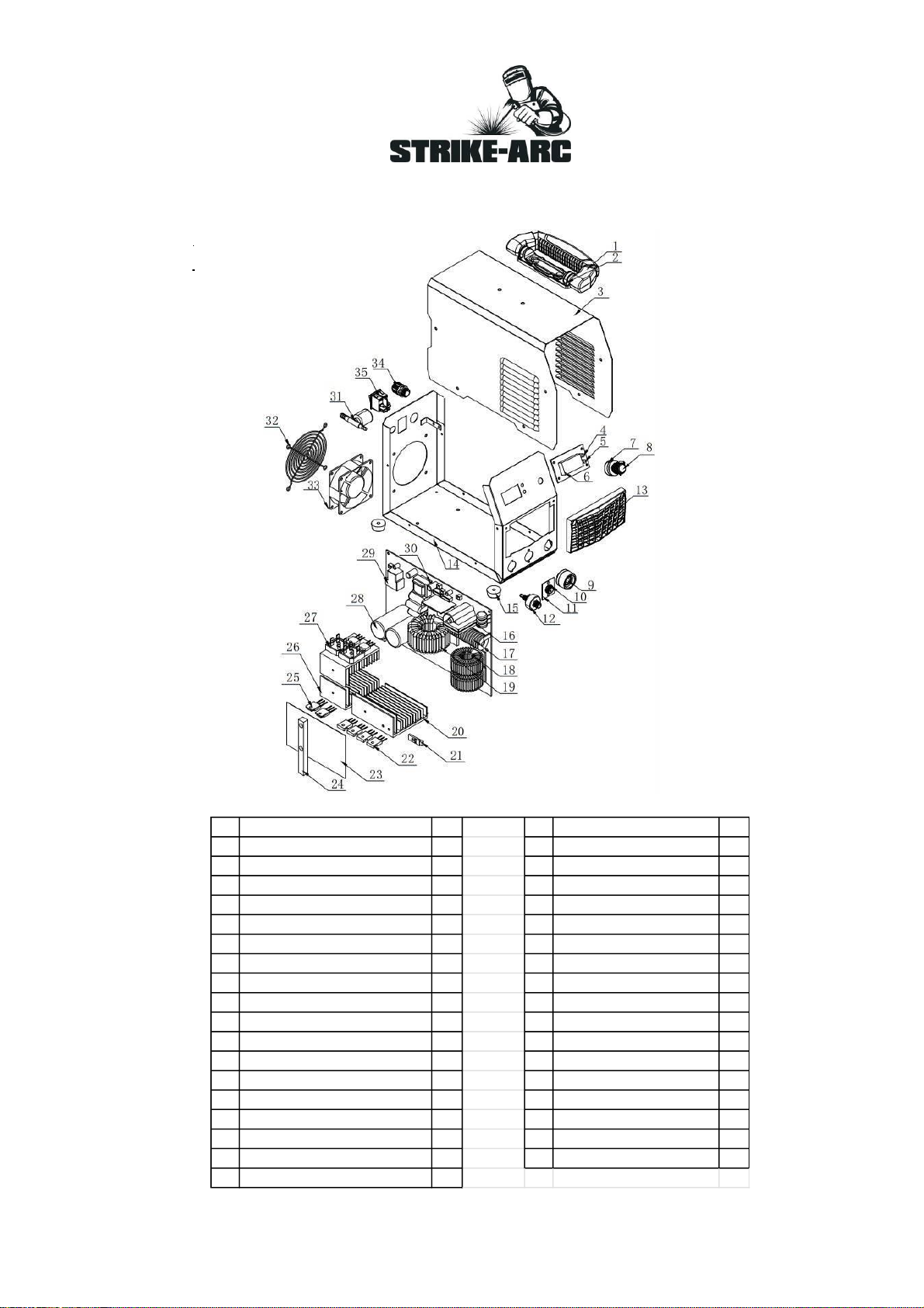
PARTS LISTING
No. PART QTY No. PART QTY
1. HANDLE 1 19. MAIN TRANSFORMER 1
2. HANDLE SEAT 1 20. RADIATOR 1 1
3. METAL COVER 1 21. THERMOSTAT 1
4. LED 1 22. RECTIFIER TRANSITOR 4
5. LED 1 23. BAKELITE 1
6. DIGITAL DISPLAY 1 24. UPRIGHT 1
7. POTENTIALMETER 1 25. IGBT 4
8. POTENTIALMETER KNOB 1 26. RADIATOR 2 2
9. FAST CONNECTOR 1 27. RECTIFIER BRIDGE 2
10. AVIATION SOCKET 1 28. CAPACITOR 2
11. BRACKET 1 29. RERLAY 4
12. P&E INTEGRATED CONNECTOR 1 30. DRIVE TRANSFORMER 1
13. PLASTIC FRONT PANEL 1 31. SOLENOID VALVE 1
14. METAL BOTTOM BOARD 1 32. FAN COVER 1
15. RUBBER FEET 4 33. FAN 1
16. HIGH PRESSURE PAGAGE 1 34. POWER CABLE FASTENER 1
17. COUPLING TRANSFORMEFR 1 35. SWITCH 1
18. TRANSFORMER 2
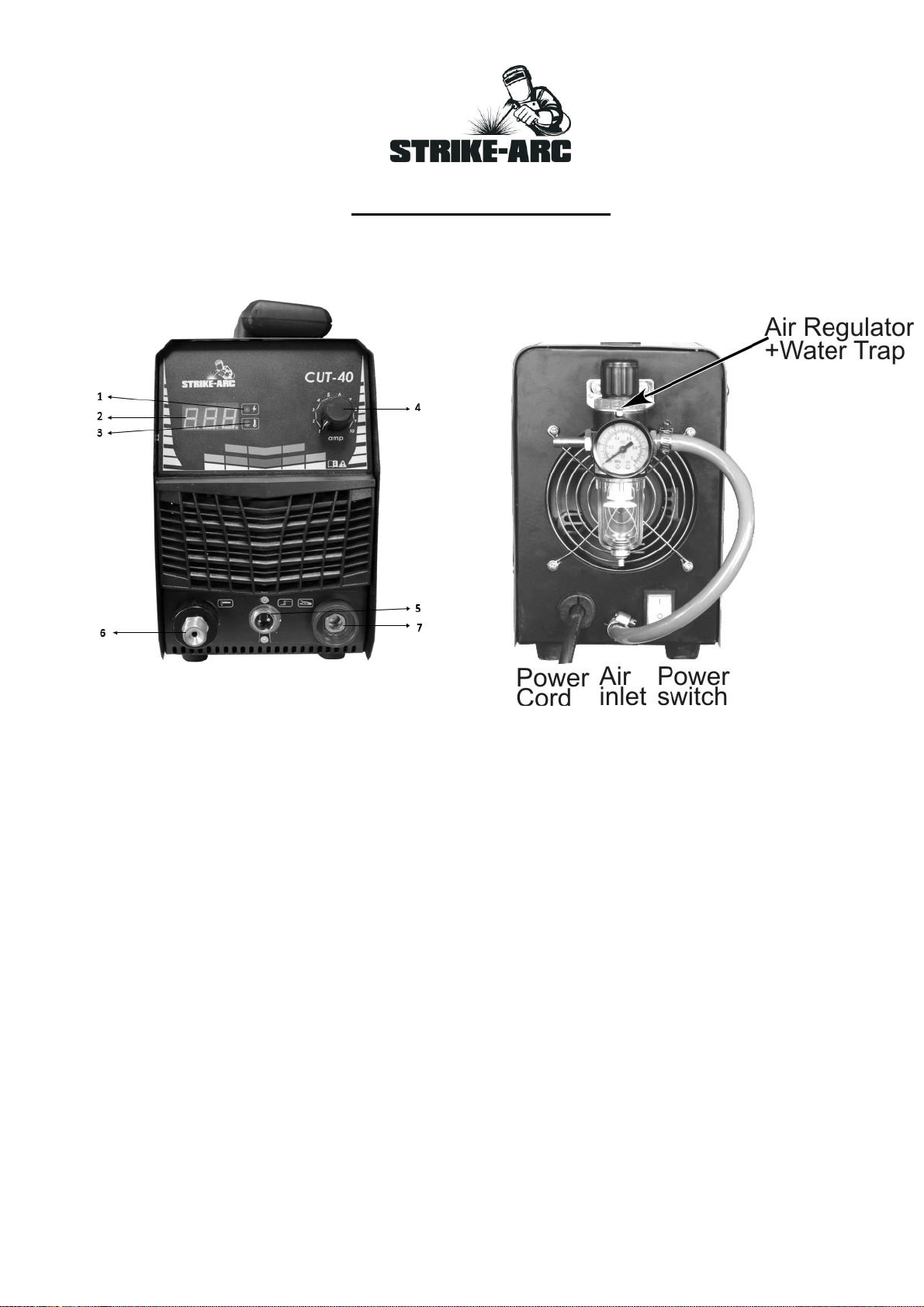
PANEL INSTRUCTION
Model: SACUT40
1. POWER INDICATOR LIGHT
2. CURRENT METER
3. OVER-LOAD (HEAT) INDICATOR LIGHT
4. CURRENTADJUSTER
5. TORCH AVIATION SOCKET OUTLET
6. NEGATIVE OUTPUT (TORCH)
7. POSITIVE OUTLET (EARTH CLAMP)

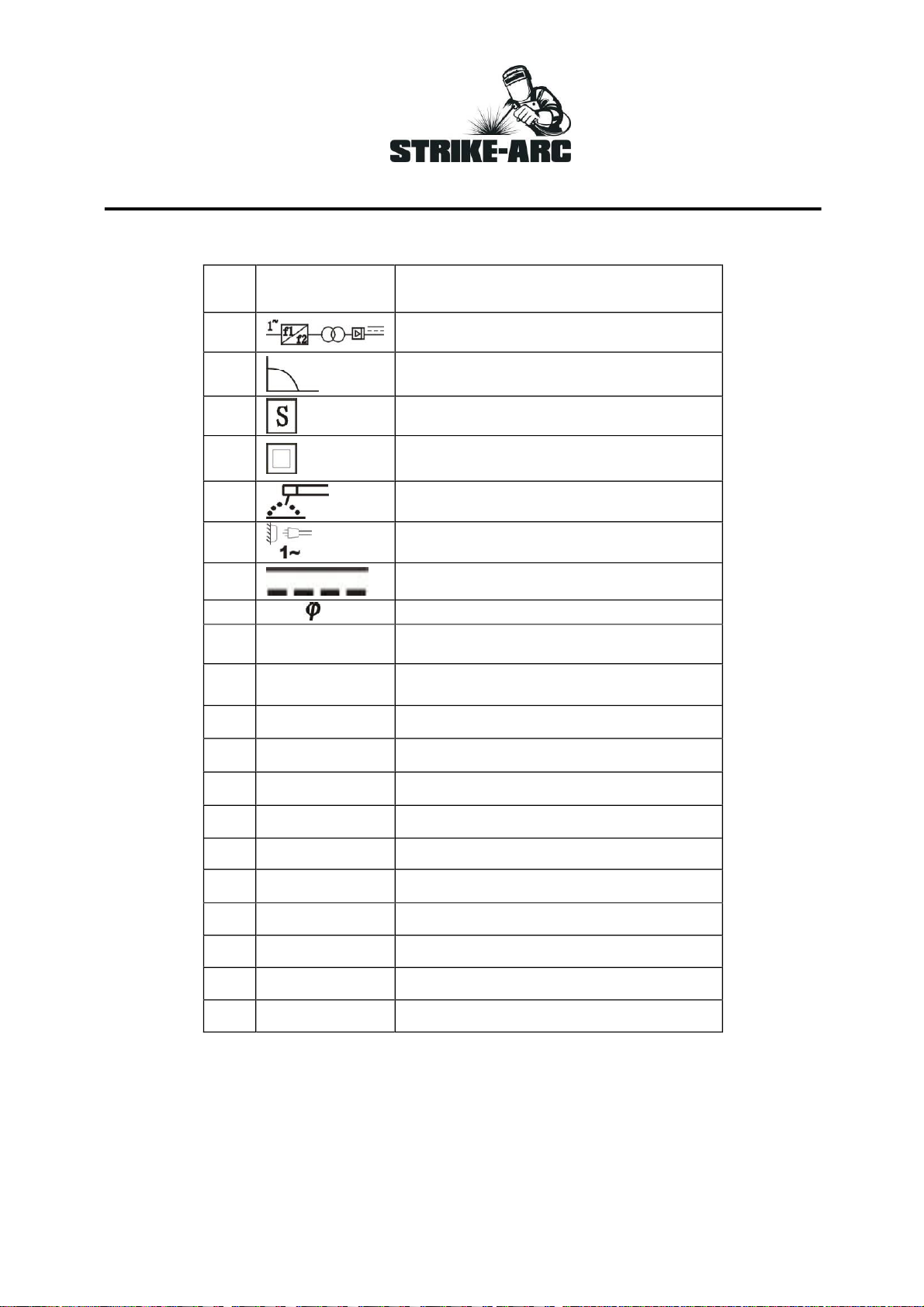
NAMEPLATE SYMBOL AND GRAPHIC MEANING
NO.
Symbol
Meanings
1
Single phase static frequency
changer-transformer-rectifier
2
Static External Characteristics is
dropping characteristic
3
Welding Power source symbol of
Fit welding operation
4
II Category Protection Symbol
5
Manual arc welding with coated
electrode
6
/ 3~
Single phase power source/ three
phase power source
7
DC (direct current)
8
COS
Power Factor
9
IEC60974-1
Confirmed Welding power source
files quote
10
~50/60Hz
AC power, rated frequency
50HZ/60HZ
11
U0(V)
No load voltage unit: V
12
X
Symbol for load continuance rate
13
I2(A)
Rated welding current unit: A
14
U2(V)
Rated load voltage unit: V
15
…%.....100%
Duty cycle
16
I1(A)
Rated Input current unit: A
17
U1(V)
Rated Input voltage unit: V
18
I CL.H
Insulation Class
19
IP21S
Protection Degree
20
COOLING AF
Fan cooling

After-sales Service
This machine is covered by the manufacturer’s warranty for a period on 12 months from date of
purchase against faulty material and or poor workmanship. Misuse/abuse and tampering of the
machine will not be covered by the warranty. Contact your dealer for repair/warranty claims.
Packing List
Name
NO.
Main Body
1
Cutting Torch
1
Pressure Reducing Value
1
Ground Wire
1
Manual
1
Strike-Arc products are exclusively manufactured for and distributed by Agrinet(Pty)
Ltd.
Private Bag x165,Centurion,0046
T: +27(0) 12 657 2222
Made in PRC
Table of contents


