Studio Technologies StudioComm 76DA User manual
50241-0514, Issue 9
© 2014 by Studio Technologies, Inc., all rights reserved
www.studio-tech.com
Model 76DA Central Controller and
Model 77 Control Console
User Guide
Issue 9, May 2014
This User Guide is applicable for systems consisting of:
Model 76DA: serial number M76DA-01151 and later
with software version 4.20 and higher and FPGA version 4.12 and higher;
Model 77: serial number M77-00151 and later with software version 4.20 and higher
for Surround

This page intentionally left blank.

Model 76DA/77 User Guide Issue 9, May 2014
Studio Technologies, Inc. Page 3
for Surround
Table of Contents
Introduction ................................................................... 5
Installation .................................................................... 9
Configuration ................................................................17
Operation ......................................................................39
Technical Notes ............................................................46
Specifications ...............................................................50
Appendix A—Connection Pin-Out Charts ....................52
Appendix B—Sync Input Sources ................................53

Issue 9, May 2014 Model 76DA/77 User Guide
Page 4 Studio Technologies, Inc.
for Surround
This page intentionally left blank.

Model 76DA/77 User Guide Issue 9, May 2014
Studio Technologies, Inc. Page 5
for Surround
Introduction
What This User Guide Covers
This User Guide is designed to assist
you when installing and using the Model
76DA Central Controller and one or more
associated Model 77 or Model 71 Control
Consoles.
Overview
As creating and distributing multi-channel
surround (5.1) and stereo audio mate-
rial has become a day-to-day reality, the
ability to simply and effectively monitor
these sources is imperative for recording,
post-production, and broadcast facilities.
And with audio-with-picture applications
becoming so prevalent, additional monitor-
ing challenges have arisen. Studio Tech-
nologies has addressed these needs with
the StudioComm for Surround Model 76DA
Central Controller and the Model 77 and
Model 71 Control Consoles. With digital
audio inputs, digital and analog monitor
outputs, support for multiple user control
surfaces, and an extensive set of operating
resources it’s a simple task to integrate a
monitoring system into virtually any facility.
The carefully selected group of features,
including surround and stereo inputs, con-
figurable input-signal time delay, multiple
pre- and post-fader outputs, configurable
downmix and mute/solo functions, and bass
management, along with a multi-format
sync input, make the system powerful yet
simple to operate. And by using the best of
contemporary technology, as well as follow-
ing rigorous design practices, the system’s
audio quality is excellent.
A StudioComm for Surround system starts
with the Model 77 Control Console. It’s the
system’s “command center” and is designed
to reside at an operator’s location, allow-
ing fingertip selection of all monitoring
functions. Numerous LED indicators pro-
vide complete status information. A 4-digit
numeric display indicates the post-fader
monitor output level in real time. A major
strength of the Model 77 is its ability to
configure, under software control, many
important operating parameters. Intended
for secondary monitoring locations, the
Model 71 Control Console is a compact
user control surface. It provides three of
the most basic functions: a rotary level
control, dim on/off button, and reference
level on/off button.
While many installations will use only one
Model 77 Control Console, up to three
additional Model 77 or Model 71 Control
Consoles can also be connected. This
provides multiple users with full control
over a facility’s monitor system. And to
make installation simple, the Model 76DA
provides power for all connected Model 77
or Model 71 units.
The core of this StudioComm for Surround
system is the Model 76DA Central Con-
troller. The one-rack-space unit contains
circuitry that supports digital audio inputs,
digital and analog monitor outputs, pro-
cessing, and the user interface. The Model
76DA provides two surround (5.1) and
three stereo digital audio inputs. These
unbalanced digital inputs are AES3/
SMPTE 276M-compliant; sources of this
type are ubiquitous in most post-produc-
tion and broadcast environments. The in-
puts allow a sample rate of up to 192 kHz
and a bit depth of up to 24 to be directly
supported. Circuitry associated with one
of the stereo inputs provides sample rate
conversion (SRC) capability, allowing a
wide range of digital audio sources to be
monitored. Up to 340 milliseconds of input
Issue 9, May 2014 Model 76DA/77 User Guide
Page 6 Studio Technologies, Inc.
for Surround
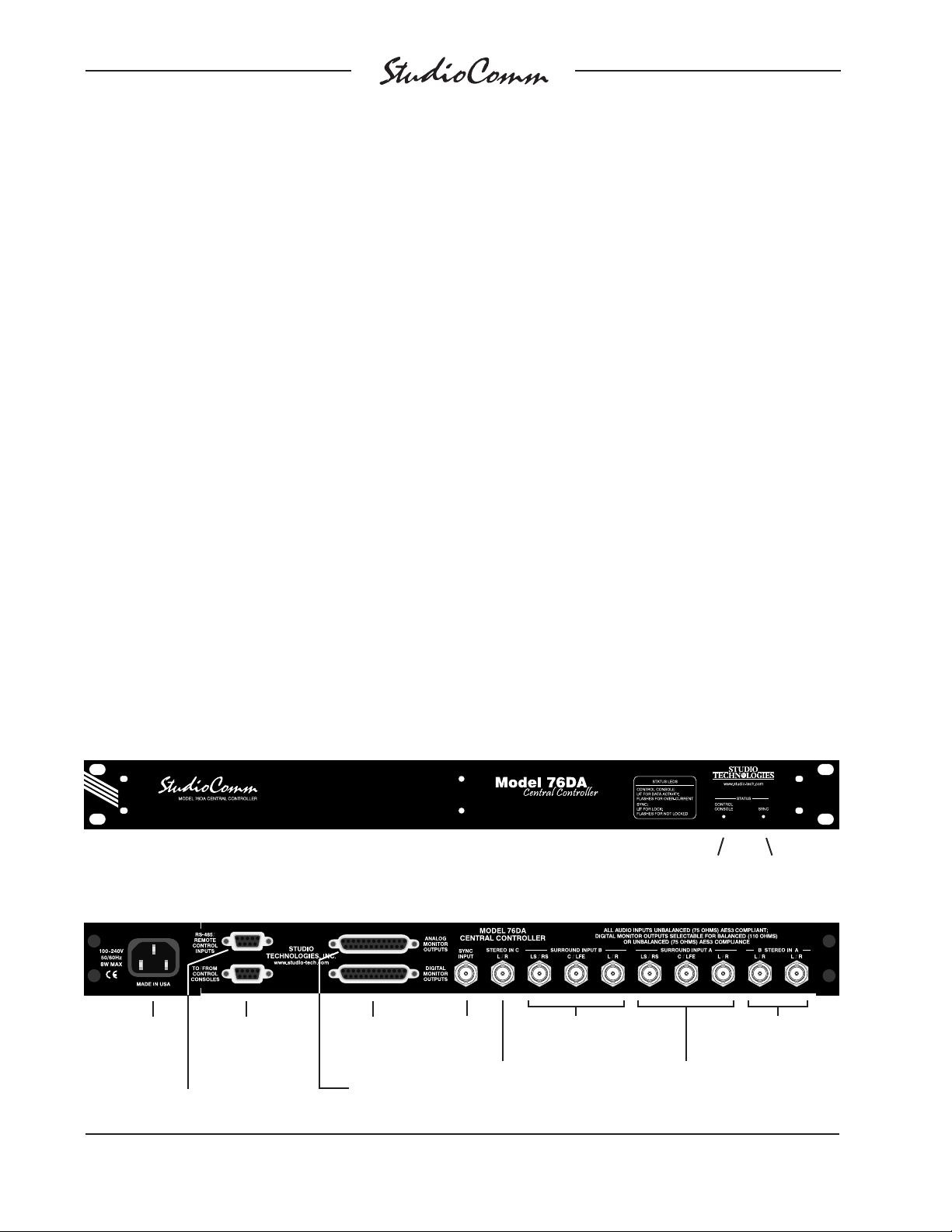
Figure 1. Model 76DA Central Controller Front Panel
Figure 2. Model 76DA Central Controller Back Panel
Sync status
LED
Control console
status LED
Sync
Input
Surround Input B
Surround Input A
Stereo Input A and
Stereo Input B
Stereo
Input C
delay can be selected to compensate for
processing delays in an associated video
path. For flexibility, two delay values can be
configured, allowing real-time selection as
desired. A number of different signals can
serve as the Model 76DA’s digital audio
timing reference. For synchronization with
a master timing reference a dedicated
source of word clock, DARS (AES11), bi-
level video, or tri-level video can be connect-
ed. Alternately, the L/R connection of the
actively selected surround or stereo input
source can serve as the timing reference.
A range of digital and analog surround (5.1)
and stereo digital monitor outputs are pro-
vided. The post-fader surround and stereo
digital and analog monitor outputs are in-
tended for connection to monitor loudspeak-
er systems. The pre-fader surround digital
monitor output can be used with metering
systems that require signals that aren’t
impacted by level control or other monitor-
ing functions. The stereo input C direct
digital monitor output allows an installation
to directly access the SRC capabilities.
For installation flexibility the digital monitor
outputs can be configured for compatibil-
ity with equipment that requires balanced
or unbalanced AES3 digital audio signals.
When selected for balanced AES3 compat-
ibility the output impedance is 110 ohms
with a signal level of 5 volts peak-to-peak
(Vpp). For unbalanced AES3 operation
the impedance is 75 ohms and the level
is 1 Vpp.
A sophisticated bass management func-
tion is integral to the Model 76DA’s design
and can be enabled if desired. It can apply
to both the surround and stereo digital and
analog post-fader monitor output channels.
Note however that the bass management
function is only supported at sample rates
of 44.1, 48, 88.2, and 96 kHz. The overall
goal of bass management is very simple:
ensure that the entire audio bandwidth of
all channels can be accurately monitored.
Many loudspeaker systems have inherent
low-frequency limitations, preventing a true
picture of the source material from being
presented. To overcome this, the low-
Digital monitor
outputs
To/from
Models 77 & 71
Control Consoles
AC mains
input
Remote control inputs
Analog monitor
outputs
Model 76DA/77 User Guide Issue 9, May 2014
Studio Technologies, Inc. Page 7
for Surround
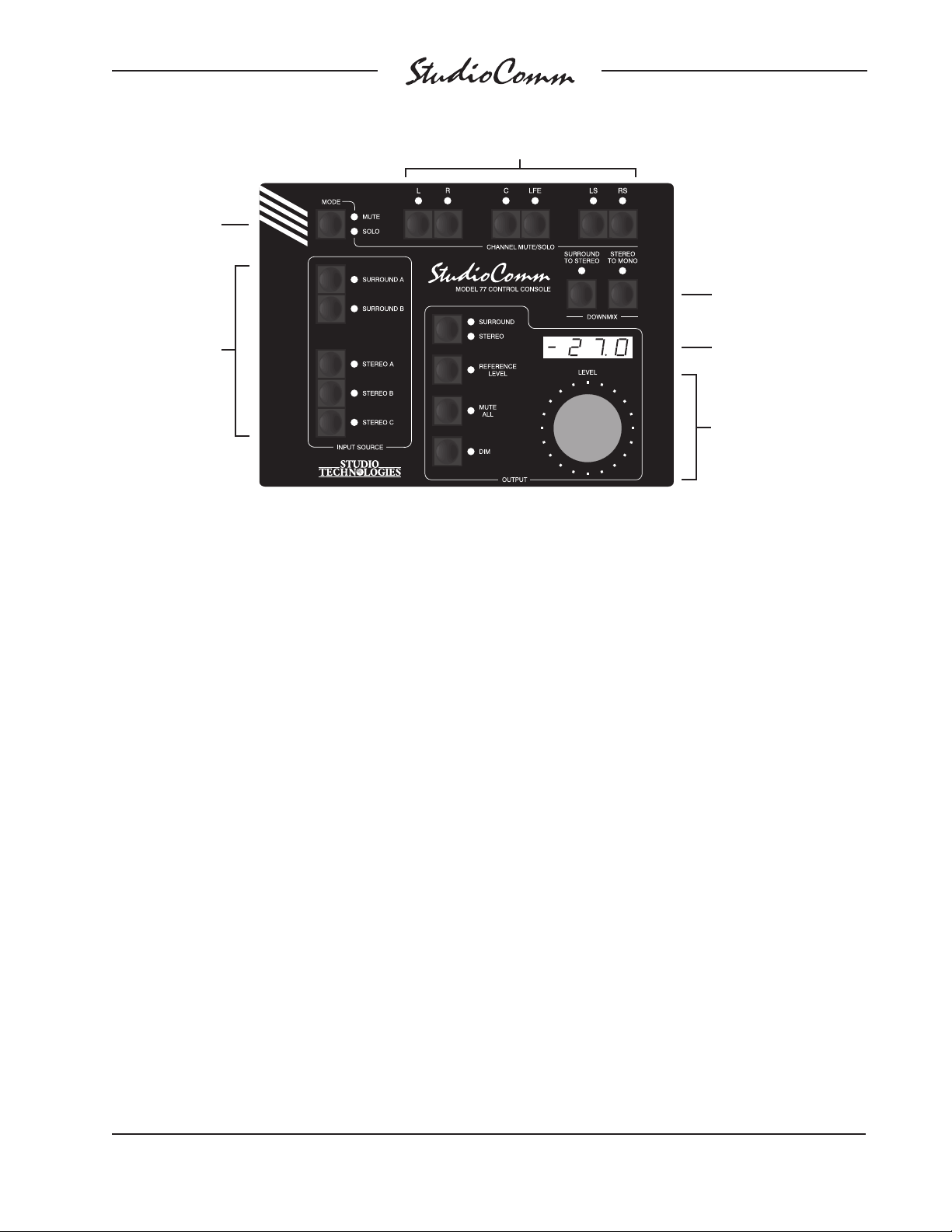
Figure 3. Model 77 Control Console Front Panel
Channel mute/solo
Mute/solo
mode
Post-fader surround
monitor output
• Surround/stereo
• Reference level
• Mute all
• Dim
• Rotary level control
Monitor output
level display
Input source
select
Downmix
frequency energy from the five surround
and two stereo channels can be separated
and then routed to the subwoofer loud-
speaker. Several of the bass management
functions can be configured to match the
requirements of specific installations.
Great care was taken in designing the
system’s architecture, ensuring that the
character of the audio input signals is pre-
served. All audio processing, including bass
management, is performed in 32 bits using
a high-speed field-programmable gate array
(FPGA) integrated circuit.
The Model 76DA occupies one space (1U)
in a standard 19-inch rack. Digital audio
sources are interfaced with the Model 76DA
using nine BNC connectors. A tenth BNC
connector is used by the sync source.
Digital and analog monitor output signal
connections are made using two 25-pin
female D-subminiature connectors. One
9-pin female D-subminiature connector
is used to connect the Model 76DA with
up to four Model 77 or Model 71 Control
Consoles. A second 9-pin female “D-sub”
connector is used to interface with remote
control signals. AC mains power is
connected directly to the Model 76DA,
with an acceptable range of 100 to 230
volts, 50/60 Hz.
Additional Details
The Model 77 provides five buttons and as-
sociated LEDs for selection of the surround
and stereo input sources to be monitored.
While in most cases only one input source
will be monitored at a time, stereo input C
can be selected for simultaneous monitoring
with one of the two surround or other two
stereo inputs. This allows the two selected
inputs to be combined (“summed”).
It’s interesting to note that while each of the
two surround inputs has an LFE channel
associated with it, the “.1” post-fader digital
and analog surround monitor outputs are
designated as SUB (subwoofer), rather than
LFE. This terminology was carefully selected
to highlight the fact that this output channel
may include more than just LFE content.
The bass management function, if enabled,

Issue 9, May 2014 Model 76DA/77 User Guide
Page 8 Studio Technologies, Inc.
for Surround
will redirect low-frequency energy from the
main input channels, combing it with the
LFE content before routing the sum to the
digital and analog subwoofer outputs.
The post-fader surround and stereo digital
and analog monitor output levels can be
controlled by way of a large, easy-to-use
rotary control. The control, actually a digital
encoder, allows level selection in precise
0.5-dB steps. The auto mute all function
causes the post-fader surround and stereo
monitor output channels to automatically
mute whenever the output level control
reaches maximum attenuation. Using the
reference level function, the post-fader
surround and stereo monitor output levels
can be set to a pre-configured value. This is
provided for audio-with-picture applications
that require a specific monitor output level.
The reference level is easily configured
by taking an electronic “snapshot” of the
desired monitor output level. For opera-
tor confirmation a 4-digit LED readout can
display the level of the post-fader sur-
round and stereo monitor output channels.
To match the needs of a facility, it can be
configured to display either the attenuation
level or the sound pressure level (SPL).
The dim function allows the post-fader
surround and stereo digital and analog
monitor output levels to be reduced by a
fixed dB amount. The dim level is config-
ured from among four available values. A
mute all function allows the post-fader sur-
round and stereo monitor output channels
to be simultaneously muted. The channel
mute/solo section provides post-fader sur-
round and stereo channel monitoring con-
trol, allowing a single channel to be muted
or monitored. Multiple channels can also
be simultaneously selected for muting or
“soloing.”
A special solo mode is also provided,
called channel pop solo, which offers a
unique aid in monitoring audio material.
Channel pop solo allows the level of a
single post-fader digital and analog moni-
tor output channel to be raised while the
level of the other channels is reduced. This
helps to emphasize the content on one
channel without fully muting the others.
Broadcast applications can benefit from
the channel pop solo mode by allowing, for
example, the center channel to be high-
lighted while still maintaining some level on
the other channels. The amount of level in-
crease—the “pop”—as well as the amount
of attenuation can be configured to meet
the needs of specific applications or users.
Two functions allow the input sources to
be checked for level or phase inconsis-
tencies. The surround to stereo downmix
function is used to create a stereo signal
from the selected surround (5.1) source.
Key operating parameters in the surround
to stereo downmix function can be config-
ured to meet the requirements of an appli-
cation. This can be especially useful when
support for specific international broadcast
standards is required. The stereo to mono
downmix function allows audio on the left
and right channels to be added (summed)
and monitored on the center output chan-
nel. The two downmix functions can be
simultaneously enabled, allowing a sur-
round source to be checked for mono com-
patibility. The downmix functions always
impact the post-fader surround and stereo
monitor outputs. A configuration setting
allows the pre-fader surround monitor out-
put to be selected for pre- or post-downmix
operation.
For flexibility, the StudioComm for Sur-
round system is designed to easily inte-
grate with equipment such as production

Model 76DA/77 User Guide Issue 9, May 2014
Studio Technologies, Inc. Page 9
for Surround
intercom systems, on-air or recording tally
signals, and audio consoles. Two remote-
control inputs provide access to the mute
all and dim functions. By providing access
to these functions, talkback or slate activity
from an audio console or other communi-
cations system can control the level of the
post-fader surround and stereo monitor
outputs.
Installation
In this section you will be installing the
Model 76DA Central Controller in an equip-
ment rack. Connections to the digital audio
inputs, digital monitor outputs, and analog
monitor outputs will be made. A dedicated
digital audio timing reference signal can
be connected to the sync input. If desired,
external equipment will be interfaced to
the remote control inputs. A location will
be selected for the first Model 77 Control
Console and it will be connected to the
Model 76DA. AC mains power will be con-
nected to the Model 76DA. For advanced
applications up to three additional Model
77 or Model 71 Control Console units can
be connected to the Model 76DA.
System Components
The main shipping carton contains one
each of the following: Model 76DA Central
Controller, Model 77 Control Console,
9-pin D-sub interconnecting cable, and
user guide. Also included in the ship-
ping carton is a North-American-standard
AC mains cord. Your dealer or distributor
should provide an AC mains cord appropri-
ate for destinations outside of North
America. Any additional Model 77 or
Model 71 Control Consoles will be
shipped in separate cartons.
Mounting the Model 76DA
The Model 76DA Central Controller re-
quires one space (1U) in a standard 19-
inch (48.3 cm) equipment rack. Secure
the Model 76DA into the equipment rack
using two mounting screws per side. Se-
lect a location that is convenient for making
connections to the audio signals as well
as interfacing with the first (or only) Model
77 Control Console. A cable is supplied
to connect the Model 76DA to the Model
77. If the needs of a specific installation
dictate, an alternate-length interconnecting
cable can be fabricated and used.
Audio Connections
Audio connections are made by way of
nine BNC jacks and two 25-pin female
D-subminiature connector. All the connec-
tors are located on the Model 76DA’s back
panel. Refer to Figure 2 for a detailed view
of these jacks and the connector.
Audio Inputs
Two surround (5.1) and three stereo digital
audio sources can be connected. All sourc-
es can be monitored using the pre- and
post-fader surround and post-fader stereo
monitor output channels. A one-to-one
relationship is maintained between the
input and output channels, i.e., left input
to left monitor output, right input to right
monitor output, center input to center
monitor output, etc. (Of course this won’t
be true in the case where the user has
enabled one or both of the downmix func-
tions.) Stereo input C is also routed to the
stereo input C direct monitor output.
The audio inputs support digital audio sig-
nals with a sampling rate of up to 192 kHz
and a word length (depth) of up to 24 bits.
It’s best if the connected signal sources

Issue 9, May 2014 Model 76DA/77 User Guide
Page 10 Studio Technologies, Inc.
for Surround
maintain a common sample rate and tim-
ing reference. Having all signals “locked”
together helps to ensure proper handling
by the Model 76DA’s all-digital signal
control path.
There is, however, an exception worth
noting. Circuitry associated with stereo
input C has sample rate conversion (SRC)
capability, allowing virtually any digital
audio signal to be connected. A signal
connected to stereo input C can have an
independent sample rate and timing refer-
ence and still be monitored correctly. Refer
to the Technical Notes section of this guide
for a detailed review of the SRC capability.
Nine BNC jacks on the Model 76DA’s
back panel are used to interface with the
18 channels associated with the digital
audio signal sources; each BNC connector
carries two audio channels. The digital
audio inputs are intended for connection
with unbalanced digital audio sources that
are compatible with the AES3 standard. In
broadcast or post-production environments
these signals may also be referred to as
following the SMPTE 276M standard. This
signal type has a nominal impedance of 75
ohms with a nominal signal level of 1 Vpp.
As expected, these digital audio sources
should be provided in the form of coaxial
cables with BNC plugs attached.
Balanced AES3 digital audio signals
can also be used with the Model 76DA’s
inputs if external coupling transformers
(“baluns”) are utilized. These impedance-
matching (110 ohms to 75 ohms) and
level-attenuating transformer assemblies
typically provide a 3-pin female XLR con-
nector on their input and a female BNC
connector on their output.
Digital Monitor Outputs
The 25-pin female D-subminiature con-
nector labeled Digital Monitor Outputs
provides access to the Model 76DA’s 16
channels of digital audio monitor output:
pre-fader surround, post-fader surround,
post-fader stereo, and stereo input C
direct. The pre-fader surround digital
monitor output channels are intended
for connection to metering or monitoring
equipment that requires uninterrupted full-
level signals.
The post-fader surround digital monitor
output channels are intended to connect to
a 5.1 loudspeaker system. The post-fader
stereo digital monitor output is provided to
support a separate set of stereo monitor
loudspeakers.
The stereo input C direct digital monitor
output is essentially a unity gain copy of
the signal connected to stereo input C.
However, the signal does pass through the
sample rate conversion (SRC) and input
delay circuitry. The impact made by these
functions will depend on the specific input
signal and the Model 76DA’s configuration
settings.
For flexibility the digital monitor outputs
are transformer-coupled and can be con-
figured to act as balanced or unbalanced
AES3 digital audio sources. The digital
monitor outputs are configured in two
groups with separate choices available
for the pre-fader surround/stereo input C
direct group and post-fader surround/post-
fader stereo group. When a group is set for
balanced AES3 operation the signals have
a nominal impedance of 110 ohms and a
nominal level of 5 Vpp. Signals of this type
are normally interconnected using shielded
twisted-pair cable terminated with 3-pin

Model 76DA/77 User Guide Issue 9, May 2014
Studio Technologies, Inc. Page 11
for Surround
XLR connectors. When a group is config-
ured for unbalanced AES3 operation the
signals have a nominal impedance of 75
ohms and a nominal level of 1 Vpp. These
signals are typically interconnected using
coaxial cable terminated with BNC connec-
tors. For details on how a Model 77 Control
Console is used to select the digital moni-
tor output types refer to the Configuration
section of this user guide.
A cable assembly with a 25-pin male D-
sub connector (DB-25M) on one end and
the desired connectors on the other end
will be used for connecting to the digital
monitor outputs. The D-subminiature con-
nector follows the TASCAM® wiring con-
vention, organizing the 25 pins into eight
groups of three pins each; one pin remains
unused. Each set of three pins provides an
independent interface. In the analog world
this would allow eight audio signals to be
transported. But with AES3 digital audio
signals this allows support for 16 audio
channels; eight interfaces each supplying
two audio channels.
A wiring assembly prepared for the Model
76DA’s digital monitor outputs, when con-
figured for balanced AES3 (110 ohms/
5 Vpp), would be identical to that of a DA-
88-style output assembly. An assembly
of this type would have a 25-pin male D-
subminiature connector (DB-25M) on one
end and eight 3-pin male XLR connectors
on the other. A wiring assembly prepared
for the Model 76DA’s digital monitor out-
puts, when set for unbalanced AES3
(75 ohms/1 Vpp), would typically have
eight BNC plugs attached.
For compatibility with balanced AES3
digital audio signals connect the D-sub’s +
terminal as signal high and the – terminal
as signal low. In most applications a 3-pin
male XLR connector will be used. In this
case the + terminal would go to pin 2 of the
XLR, the – terminal to XLR pin 3, and the
shield terminal to XLR pin 1.
For compatibility with unbalanced AES3
digital audio signals connect the D-sub’s
+ terminal as signal high, and both the
– and shield terminals as the signal low/
shield. When terminating to a BNC plug the
D-sub’s + terminal should connect to the
center pin; the – and the shield connec-
tions should go to the “body” of the BNC
plug. To clarify, for optimal operation it is
best to connect both the – and shield con-
nectors together directly on the D-sub plug,
rather than at the BNC end of the interface
assembly. Note that the output circuitry is
transformer-coupled so it is possible to just
connect to the + and – terminals and still ex-
perience correct operation. This would leave
the shield connection unterminated.
Refer to Figure 4 or Appendix A for the
exact connection details. Note that unlike
a DA-88-style assembly, the two threaded
fasteners associated with the Model 76DA’s
D-sub connectors use 4-40 threads. This
complies with the original design standard
for D-subminiature connectors.
Pre-Fader Surround Digital Monitor
Output
The pre-fader surround digital monitor
output channels are intended to connect
to metering, measurement, or other
signal monitoring equipment that requires
uninterrupted, full-level digital audio signal
sources.
Stereo Input C Direct Digital Monitor
Output
The stereo input C direct digital monitor
output is intended for use in site-specific
applications. It provides an uninterrupted,

Issue 9, May 2014 Model 76DA/77 User Guide
Page 12 Studio Technologies, Inc.
for Surround
full-level digital audio signal source that
is post-SRC and input delay in the signal
chain.
Post-Fader Surround Digital Monitor
Output
The post-fader surround digital monitor out-
put channels are designed for connection
to digital inputs on audio amplifiers associ-
ated with monitor loudspeakers. Alternately,
they could be connected to the inputs of
loudspeakers that contain integrated ampli-
fiers with digital audio input capability.
Post-Fader Stereo Digital Monitor
Output
The post-fader stereo digital monitor output
channels are intended to support a stereo
loudspeaker system, either by connecting
to the digital input of an amplifier associ-
ated with a set of loudspeakers or directly
to a set of amplified speakers that provide
digital inputs.
Analog Monitor Outputs
The connector labeled Analog Monitor
Outputs provides access to the Model
76DA’s 6-channel (5.1) surround and
2-channel stereo analog monitor outputs.
The surround analog monitor output chan-
nels are intended to connect to analog
inputs associated with the surround loud-
speaker system incorporated in a facility.
The stereo analog monitor output allows
support for a secondary set of stereo moni-
tor loudspeakers.
The analog monitor output channels are
designed for connection to audio amplifiers
associated with monitor loudspeakers or
to the inputs of loudspeakers that contain
integrated amplifiers. The analog monitor
outputs are electronically balanced and
will perform optimally when driving loads
of 2000 (2 k) ohms or greater. In most ap-
plications 3-pin male XLR connectors will
be used to interface with the inputs on the
associated amplifiers or amplified speakers.
In this case the + terminal would go to pin 2
of the XLR, the – terminal to XLR pin 3, and
the shield terminal to XLR pin 1.
Balanced operation of the analog monitor
outputs is the preferred connection method
but unbalanced operation does not pose a
problem. To connect to an unbalanced load
connect the + terminal as signal high, and
only the Model 76DA’s shield terminal as
the signal low/shield. Leave the – terminal
unconnected. For correct unbalanced
operation, it is important not to connect
– and shield together.
The wiring scheme used by the D-sub-
miniature connector complies with that
made popular by TASCAM with their DA-88
product. A wiring assembly prepared for
the Model 76DA’s analog monitor outputs
TASCAM® Signal Signal
Connections Channel High (+) Low (–) Shield
Pre-Fader L/R 1 24 12 25
Pre-Fader C/SUB 2 10 23 11
Pre-Fader LS/RS 3 21 9 22
Stereo Input C Direct 4 7 20 8
Post-Fader L/R 5 18 6 19
Post-Fader C/SUB 6 4 17 5
Post-Fader LS/RS 7 15 3 16
Post-Fader Stereo 8 1 14 2
Notes: 1) All signals transformer-coupled digital audio;
selectable for balanced or unbalanced AES3
compatibility.
2) Connector type on Model 76DA is 25-pin female
D-subminiature (DB-25F). Installer must provide male
(DB-25M). Connector uses 4-40 threaded inserts for
locking with mating plug.
3) Wiring scheme follows TASCAM DA-88 convention.
Standard DA-88-type wiring harnesses are directly
compatible, with the possible exception of 4-40 screw
threads being required.
Figure 4. Connections for Digital Monitor Outputs

Model 76DA/77 User Guide Issue 9, May 2014
Studio Technologies, Inc. Page 13
for Surround
is identical to that of a DA-88-style out-
put assembly. Please refer to Figure 5 for
the exact connection details. Again note
that unlike a DA-88-style assembly, the
Model 76DA’s D-sub connectors use 4-40
threads.
be in one of several formats: word clock,
DARS (AES11), bi-level video, or tri-level
video.
An overview of the various compatible
timing reference signals might prove
worthwhile. Word clock is a digital signal
that is locked in phase and frequency to
the sample rate of the associated digital
audio sources. DARS (digital audio refer-
ence source) is a timing signal compliant
with the AES11 standard. It’s sometimes
referred to as “AES3-black.” Technically it is
similar to an AES3 signal but is generated
specifically as a timing reference signal.
Bi-level video sync signals were originally
provided to support NTSC and PAL broad-
cast applications, although they continue
to be used by contemporary equipment.
Tri-level sync signals were primarily asso-
ciated with facilities that supported high-
definition (HD) video equipment, however
the importance of this type of sync seems
to be waning. Both bi-level and tri-level
signals can be found at numerous rate
combinations, configured to allow for com-
patibility with the various video formats.
With the wide range of allowable sync
sources proper Model 76DA operation
should be easy to obtain. Extensive testing
has been done using many different sync
source types and rates. Interested users
can refer to Appendix B of this user guide
for details.
The external sync reference source is con-
nected to the sync input BNC connector
located on the Model 76DA’s back panel.
For flexibility this input can be configured
to be high-impedance (“floating”) or ter-
minated with an impedance of 75 ohms.
A sync source that is dedicated for use by
the Model 76DA’s sync input will typically
have input termination enabled. If the sync
Signal Signal
Connections High (+) Low (–) Shield
Surround L 24 12 25
Surround R 10 23 11
Surround C 21 9 22
Surround SUB 7 20 8
Surround LS 18 6 19
Surround RS 4 17 5
Stereo L 15 3 16
Stereo R 1 14 2
Notes: 1) Connector type on Model 76DA is 25-pin female
D-subminiature (DB-25F). Installer must provide
male (DB-25M). Connector uses 4-40 threaded inserts
for locking with mating plug.
2) Wiring scheme follows TASCAM DA-88 convention.
Standard DA-88-type wiring harnesses are directly
compatible, with the exception of 4-40 screw threads
being required.
Figure 5. Connections for Analog Monitor
Outputs
Sync Input
The Model 76DA requires a timing refer-
ence (sync) signal so that the digital audio
input and digital monitor output signals will
be handled correctly. A configuration set-
ting allows the source of sync to be the L/R
input of the currently selected surround
or stereo digital audio input. While this is
acceptable, audio artifacts (clicks or noise)
can occur when switching between inputs.
A better method is to connect a dedi-
cated timing reference signal to the Model
76DA’s sync input connector. The con-
nected sync signal must maintain a stable
relationship between itself and the digital
audio inputs. The actual sync source can

Issue 9, May 2014 Model 76DA/77 User Guide
Page 14 Studio Technologies, Inc.
for Surround
signal connected to the Model 76DA is be-
ing connected (“multed”) to other inputs it
may be desirable for the termination to be
disabled. A general “rule of thumb” is that
termination should be applied only at the
location of the last physical device using a
sync signal.
Remote Control Inputs
Support is provided for two remote control
input functions: remote mute all and re-
mote dim. These functions only impact the
post-fader surround and stereo digital and
analog monitor outputs. The Model 76DA’s
inputs use logic gates, “pulled up” to 5 volts
DC by way of resistors, which are active
whenever they are brought to their logic
low state. Inputs of this type are commonly
referred to as GPI inputs. While the input
circuitry is protected from over-current and
static discharge (ESD), care should be
taken to prevent nasty signals from reach-
ing them. The inputs are active only when
held in the low state; they can’t be config-
ured to change state (“latch”) in response
to a logic pulse.
A 9-pin female D-subminiature connector
is used for the remote control inputs. Refer
to Figure 6 or Appendix A for the exact
connection details. Note that pin 4 (remote
common) connects to the Model 76DA’s
internal circuit common connection as well
as to the Model 76DA’s chassis and mains
earth connections. Figure 6 also shows
two spare remote control inputs (pins 8
and 9). These are provided for future ap-
plications and should remain unconnected.
This connector also allows access to an
RS-485 data interface. This interface is
not supported in the Model 76DA and, as
such, pins 7 and 2 should remain untermi-
nated.
Connecting the Model 76DA
to the Model 77
A 9-pin female D-subminiature connector,
labeled To/From Control Consoles, is pro-
vided on the back panel of the Model 76DA
Central Controller. This is used to interface
the unit with Model 77 Control Consoles.
Refer to Figure 7 or Appendix A for details.
A 9-pin female D-sub connector, labeled
To/From Central Controller, is provided on
the back panel of each Model 77 Control
Console. A cable with 9-pin male D-sub
(DE-9M) connectors on each end is
used to interconnect the Model 76DA with
the Model 77 units. A cable is included in
the shipping carton. The cable implements
all nine connector pins in a one-to-one
manner.
Should an interconnecting cable of a differ-
ent length be required there’s no problem
for one to be fabricated and used. While it
can be wired in a one-to-one fashion sup-
porting all nine pins, only four connections
are required: pin 1 (data +), pin 6 (data –),
pin 4 (DC +), and pin 9 (DC –). The Model
76DA’s connector pin-out scheme was de-
Signal Pin Direction
Data + (RS-485/RS-422) 7 Not used
Data – (RS-485/RS-422) 2 Not used
Data Shield 1 Shield
Remote Mute All 5 Input
Remote Dim 6 Input
Remote Spare 1 8 Input
Remote Spare 2 9 Input
Remote Common 4 Common
Note: Connector type on Model 76DA is 9-pin female
D-subminiature (DE-9F). Connector uses 4-40
threaded inserts for locking with mating plug.
Figure 6. Connections for Remote Control
Inputs

Model 76DA/77 User Guide Issue 9, May 2014
Studio Technologies, Inc. Page 15
for Surround
signed to allow creation of an interconnect-
ing cable which uses commonly available
2-pair audio cable. This cable, consisting
of two twisted pairs each with an individual
shield, is typically sleek, flexible, and avail-
able in many colors. One pair and shield
can be used for the data connections while
the other pair and shield can be used for
the DC connections. This implementation
has the advantages of providing a shield
for the data path and a more robust com-
mon connection (two conductors including
the shield) for the DC power circuit.
A few simple calculations are required to
determine the maximum cable length when
connecting a Model 76DA to a Model 77.
The differential transmission scheme used
by the system’s RS-485 interface makes
an interconnection in excess of 1000 feet
(>300 meters) easily possible. The limiting
factor is typically the ability of the wiring to
pass the DC power supplied by the Model
76DA to a Model 77. The Model 76DA sup-
plies 12 volts DC with a maximum current
of 500 milliamperes.
The Model 77 requires a minimum of
9 volts DC, 100 milliamperes, for correct
operation. (The voltage must be measured
directly at the Model 77’s 9-pin connector.)
So the maximum interconnecting cable
length is directly related to the resistive
voltage losses associated with the two DC-
carrying conductors. As the Model 76DA
supplies 12 volts and the Model 77 requires
9 volts minimum, this directly leads to a
3 volt DC maximum drop due to the inter-
connecting cable. Using Ohm’s law it’s quite
easy to determine whether the selected
cable will support the desired interconnec-
tion length. Calculate the voltage drop by
multiplying the total resistance (in ohms) of
the proposed cable by 0.1 (the Model 77’s
required current in amperes). Remember to
include the resistance in both the DC + and
DC – wires when calculating the voltage
drop. If it’s greater than 3 volts your cable
is too long or the wire gauge is too small.
Additional Control Consoles
Some installations may benefit from the
Model 76DA’s ability to be controlled by
additional control consoles. At least one
Model 77 Control Console must be con-
nected to the Model 76DA Central Control-
ler. After this requirement has been met up
to three additional Model 77 or Model 71
Control Consoles can also be connected
and to powered by the Model 76DA.
When connecting multiple control consoles
to a Model 76DA all nine pins of each
interconnecting cable can be connected in
parallel (“multed”). Using this arrangement
the data and 12 volts DC power signals be-
tween all the units will be multed. A custom
cable implementation requires just four pins
to be connected: pin 1 (data +), pin 6 (data
–), pin 4 (DC +), and pin 9 (DC –).
To make installation simple, a “bus” cable
assembly can be created using a short
length of ribbon cable with one male and
multiple 9-pin female D-subminiature insu-
lation-displacement connectors attached.
Signal Pin Direction
Data + (RS-485) 1 To/From Models 77/71
Data – (RS-485) 6 To/From Models 77/71
Data Shield 2 To/From Models 77/71
DC + (12 V) 4 To Models 77/71
DC – (12 V Return) 9 To Models 77/71
DC Power Shield 5 To/From Models 77/71
Note: Connector type on Model 76DA is 9-pin female
D-subminiature (DE-9F). Connector uses 4-40
threaded inserts for locking with mating plug.
Figure 7. Connections between Model 76DA and
Model 77 and Model 71

Issue 9, May 2014 Model 76DA/77 User Guide
Page 16 Studio Technologies, Inc.
for Surround
Then standard 9-pin cables can link the
control consoles with the connectors on the
bus cable.
Refer to the previous paragraphs of this
user guide where the issues involving
Model 76DA to Model 77 cable length are
discussed. Note the required current for
a Model 77 is 100 milliamperes while a
Model 71 requires only 35 milliamperes. It’s
important to review this information prior to
creating the interconnection scheme to be
used for installing multiple Model 77 units.
AC Mains Power
The Model 76DA operates directly from AC
mains power of 100 to 230 volts, 50/60 Hz.
Being a “universal input” device, there are
no switches to set or jumpers to install to
match a location’s mains voltage. The unit
uses a 3-pin IEC 320 C14-type inlet con-
nector to mate with a detachable mains
cord. All units are supplied with a mains
cord that has a North-American-standard
plug (NEMA 5-15L) on one end and an IEC
320 C13 socket on the other. Units bound
for other destinations require that the ap-
propriate cord be used. The wire colors
in the mains cord must conform to the
internationally recognized color code and
should be terminated accordingly:
Connection Wire Color
Neutral (N) Light Blue
Line (L) Brown
Protective Earth (E) Green/Yellow
Safety Warning: The Model 76DA
does not contain an AC mains discon-
nect switch; the AC mains cord plug
serves as the disconnection device.
Safety considerations require that the
plug and associated outlet be easily
accessible to allow rapid disconnec-
tion of AC mains power should it prove
necessary.
As soon as mains power is applied the
Model 76DA will perform a power-up se-
quence. The two LEDs on the right side
of the front panel will individually light in a
rapid right-to-left test sequence. Then the
LEDs will flash in cadence while the firm-
ware loads into the Model 76DA’s main
logic device. After just a few seconds initial
system operation will commence and the
two LEDs will perform their intended func-
tions. Once operating data is being inter-
changed with the one or more connected
Model 77 or Model 71 Control Consoles
the control console status LED will also
light. The sync status LED will light if a valid
sync source has been recognized. The sync
status LED will flash if a valid sync source
is not recognized.
Also upon application of mains power, all
connected Model 77 units will go through
a power-up sequence, lighting each of its
LEDs in succession. Using its 4-digit dis-
play, each Model 77 will then momentarily
display its address, its software version, and
the main and logic device software versions
of the associated Model 76DA.
All connected Model 71 units will also go
through a power-up sequence after mains
power is applied to the Model 76DA. Each
of the Model 71’s three LEDs will light
momentarily. After these LEDs have been
lit, the device address will be shown briefly

Model 76DA/77 User Guide Issue 9, May 2014
Studio Technologies, Inc. Page 17
for Surround
using the dim and reference level LEDs,
as shown in Figure 8 in the Configuration
section. When this is complete the Model 71
will begin normal operation and its status
LED will light if communication is estab-
lished with the Model 76DA. If the Model
71’s status LED does not light check to see
if there is a device address conflict among
all connected control consoles and that all
cables are connected properly.
Should an error be detected during the
start-up process the two LEDs on the Model
76DA’s front panel will continue to flash in
cadence indefinitely. On the Model 77 units
a diagnostic code may be displayed. Refer
to the Technical Notes section of this user
guide for details.
Only after the Model 76DA and all con-
nected Model 77 and Model 71 units have
correctly powered up will full system opera-
tion begin. It’s possible that audio signals
will first be present on the digital monitor
outputs. The analog monitor outputs will
only become active after a protection inter-
val has elapsed. These outputs are muted
using electro-mechanical relays that oper-
ate under software control.
Configuration
After the physical installation has been
completed it’s important that the system’s
configuration options be carefully reviewed.
In most cases one or more of the operating
parameters will need to be revised to meet
the needs of the specific installation. Many
of the configuration parameters will impact
the signal flow in to and out of the Model
76DA Central Controller. Other parameters
affect how the one or more Model 77 Con-
trol Consoles will display status conditions
and respond to user commands. Most
of the configuration choices will be made
using a Model 77 Control Console. However,
two configuration choices are available for
each of the connected Model 71 Control
Consoles.
Configurable Parameters
Many StudioComm functions can be config-
ured to meet the exact needs of an installa-
tion. A Model 77 Control Console is used to
display and select the desired system con-
figuration. Here’s an overview of what can
be configured:
• Model 77 Device Address (must be
unique for each unit!)
• Stereo Input C Sample Rate Converter
• Post-Fader Stereo Digital and Analog
Monitor Output
• Bass Management
• Mute/Solo Bass Management Mode
• Sync Source
• Sync Input Termination
• Audio-Synced-to-Video Sample Rate
• Digital Monitor Output Types
• Reference Level
• Overall Display Mode
• Reference Level in dB SPL
• Auto Reference Level Off
• Dim Level
• Remote Inputs
• Surround to Stereo Downmix Levels
• Pre-Fader Surround Digital Monitor
Output Mode
• Channel Pop Solo Mode Offset Levels
• Input Delay A and B
• Post-Fader Digital and Analog Monitor
Output Channel Level Offsets

Issue 9, May 2014 Model 76DA/77 User Guide
Page 18 Studio Technologies, Inc.
for Surround
The configuration diagrams, located later
in this section, give details on setting each
parameter. An overview of each configu-
rable parameter is provided in the following
paragraphs.
Entering and Exiting the
Configuration Mode
A small button is located on the back of
each Model 77 Control Console, adjacent
to its 9-pin female D-sub connector. On any
connected Model 77 pressing and holding
this button for two seconds places both this
specific unit and the Model 76DA into their
configuration modes. Other connected Mod-
el 77 and Model 71 units will enter a stand-
by mode. When the Model 76DA enters its
configuration mode it will immediately mute
the monitor outputs as a speaker protec-
tion measure. When a Model 77 enters the
configuration mode its array of buttons and
LEDs no longer perform their normal func-
tions, instead they are used to display the
operating parameters and reflect configura-
tion changes as they are made.
As a user aid, a Model 77 that has entered
the configuration mode will have its mute
and solo LEDs (associated with the chan-
nel mute/solo section) light in an alternating
manner. Other connected Model 77 units
will indicate that they have entered the
standby mode by simultaneously flashing
their mute and solo LEDs.
To leave the configuration mode and return
the system to normal operation requires
one last action to be made on the Model 77
unit that’s in its configuration mode; press
and hold its configure the button for two
seconds. Note that configuration changes
are stored in nonvolatile memory only after
the configuration mode has been exited.
Our apologies to those of you who find the
configuration button a pain to use, but it’s
supposed to be that way! Seriously, the top
of the button is slightly recessed from the
back panel, making it harder to accidentally
activate. We didn’t want normal operation to
cease because someone pushed a Model
77 into a “rats nest” of schedules, memos
from management, and empty coffee cups!
But a firm press with the fleshy part of an
index finger should do the trick.
There is no problem frequently “tweak-
ing” the system’s operating parameters
to achieve the desired performance. The
configuration data is stored in nonvolatile
memory, which is rated for thousands of
read and write cycles and a retention time
in tens of years. Note that memory integrat-
ed circuits are located in the Model 76DA
Central Controller as well as the Model 77
and Model 71 Control Consoles. The in-
dividual device address is stored in each
Model 77. The device address and button
configuration parameters are stored in the
Model 71. All other configuration param-
eters are stored in the Model 76DA.
Model 77 Device Address
A unique device address must be assigned
to each Model 77 that is connected to a
Model 76DA. The choices are A1, A2, A3,
or A4, with the default address being A1. As
most installations will find only one Model
77 utilized, its default setting is appropri-
ate. For installations that use a second,
third, or fourth Model 77 each unit must be
configured with a unique device address.
Problems will occur if more than one unit
has the same address! It’s important to
highlight the fact that the device address is
the only setting that must be done on each
individual Model 77 unit. All other settings
can be made on any one of the connected

Model 76DA/77 User Guide Issue 9, May 2014
Studio Technologies, Inc. Page 19
for Surround
Model 77 units. Be sure that any selected
address does not conflict with addresses to
be assigned to Model 71 units.
Stereo Input C Sample Rate
Converter
Circuitry associated with stereo input C can
provide sample rate conversion (SRC) for
digital audio signals connected to that input.
The acceptable input range for sample rate
conversion is very wide, but is dependent
upon the output sample rate. With an out-
put sample rate of 48 kHz any signal with
a sample rate over a range of 8 to 216 kHz
can be properly monitored by the system.
This capability can be especially useful with
signals that are not synchronized with re-
spect to the others connected to the Model
76DA, even if the sample rate is identi-
cal. The only compromise is that the SRC
process adds a fixed input-to-output (group)
delay of approximately 1 millisecond, a val-
ue that shouldn’t impact most installations.
As such, it’s recommended that the sample
rate converter remain enabled. However
there might be special cases where this re-
source isn’t desired and it can be disabled.
Post-Fader Stereo Digital and
Analog Monitor Outputs
In addition to the post-fader surround digi-
tal and analog monitor outputs, separate
post-fader stereo digital and analog monitor
outputs are also provided. By default the
stereo outputs can be enabled by an opera-
tor. In applications where stereo monitor
loudspeakers are not connected to either of
the post-fader stereo monitor outputs, the
outputs can be disabled. This can minimize
confusion, preventing an operator from
attempting to select the post-fader stereo
digital and analog monitor outputs.
Bass Management
The Model 76DA incorporates flexible and
sonically excellent bass management ca-
pabilities which can impact both the digital
and analog post-fader monitor outputs. It
is, however, limited to functioning only at
sample rates of 44.1, 48, 88.2, and 96 kHz.
Five configuration parameters are used to
enable or disable bass management as
well as to select the characteristics of the
associated audio filters. While the settings
are simple to make, great care must be
taken in first reviewing the entire monitor
system. Only after a full understanding of
the performance of the associated sur-
round and, if present, stereo loudspeaker
systems are determined can a plan for
bass management be established.
Bass management can be enabled so that
the function is active when the surround
post-fader monitor outputs are enabled. It
can also be independently enabled so that
it can be active when the stereo post-fader
monitor outputs are enabled. By default
bass management for both outputs is
disabled. The crossover point of the bass
management filters can be selected from
among four choices: 40, 50, 60, or 80 Hz.
The slope of the low-pass and high-pass
filters associated with bass management
can be independently selected. The choic-
es are 12 dB/octave or 24 dB/octave with
the latter being the default.
Mute/Solo Bass Management
Mode
The Model 76DA’s mute/solo function can
be configured for how it performs in appli-
cations where bass management has been
enabled. This is a somewhat-esoteric topic
but can be important in certain situations.
The default setting for the mute/solo bass

Issue 9, May 2014 Model 76DA/77 User Guide
Page 20 Studio Technologies, Inc.
for Surround
management mode is for pre-bass man-
agement. This means that if a channel has
been selected for, as an example, soloing
then the bass management filters will send
any applicable low-frequency content to
the post-fader digital and analog subwoof-
er outputs. So in this case the solo function
is really an “input channel” solo since the
actual acoustical energy associated with
that channel will be reproduced by both the
main channel and subwoofer loudspeak-
ers. So while one is “soloing” a channel (or
set of channels) two or more loudspeakers
may be reproducing the signals.
The mute/solos bass management mode
can also be set for post-bass manage-
ment. When this mode is enabled a chan-
nel selected for soloing will cause only its
associated post-fader digital and analog
monitor output channels to remain ac-
tive. So if, for example, one of the main
surround input channels (one of the “5.”
channels) is selected for soloing then all
post-fader output channels except that one
will mute. The bass management filters
will remain enabled, thus sending only the
high-passed audio energy from the soloed
input channel to the soloed output channel.
Only if the LFE channel has been selected
for soloing will the subwoofer output re-
main active. Typically the only reason why
the post-bass management mode would
be selected is when troubleshooting issues
with the loudspeaker system.
Sync Source
The Model 76DA requires that the desig-
nated external timing reference (sync) be
defined. Three of the choices—word clock,
DARS, and video—are associated with a
signal that is connected to the sync input
BNC connector. The fourth choice allows
the L/R input of the currently selected
surround or stereo digital audio input to
serve as the system’s sync source.
Sync Input Termination
The sync input circuitry can be configured
to terminate the signal connected to the
back-panel sync input BNC connector.
When termination is selected a 75 ohm
load is applied to the signal. When the sync
input is not terminated the input impedance
is very high, essentially applying no load to
the source. If the sync source is connected
only to the Model 76DA then enabling ter-
mination is typically appropriate. However, if
the sync source is being “shared” by mul-
tiple inputs then care must be taken so that
the signal is only terminated by one device.
Audio-Synced-to-Video
Sample Rate
If a video sync signal is being used as
the Model 76DA’s timing reference
the sample rate of the connected digital
audio signals must be specified. In most
cases the default value of 48 kHz will be
appropriate, but rates from 32 to 192 kHz
are available.
Pre-Fader Surround/Stereo
Input C Direct Digital Monitor
Output Type
To meet the needs of specific installations
the nominal impedance and level charac-
teristic of the pre-fader surround and stereo
input C direct digital monitor outputs can
be selected. They are selected as a group;
configuration of individual digital outputs is
not provided. If the digital output signals are
going to be connected to balanced AES3
inputs then the setting that provides
a source impedance of 110 ohms and
a nominal 5 Vpp output level would be
This manual suits for next models
1
Table of contents
Other Studio Technologies Speakers System manuals


 owner's manual")


