Stulz Free-Air-3-IN User manual

Issue 02.2018
Free-Air-3-IN
Free cooling units
48 V DC

2
FREEAIR3IN
EN/02.2018 © STULZ SpA – all rights reserved
STULZ SpA
Via Evangelista Torricelli n.3
37067 Valeggio sul Mincio VR
ABOUT STULZ GMBH
Since it was founded in 1947, the STULZ company has
evolved into one of the world’s leading system suppliers
of air-conditioning technology. With the manufacture of
precision air-conditioning units and chillers, the sale of
air-conditioning and humidification systems and service
and object management, this division of the STULZ Group
achieved a turnover of around 370 million euros in 2014.
Since 1974 the group has seen continual international
expansion of its air conditioning technology business, spe-
cialising in A/C for data centres and telecommunications
installations. STULZ employs 2,200 workers in Germany
and seventeen subsidiaries (in France, Italy, Great Britain,
Belgium, Brazil, the Netherlands, New Zealand, Mexico,
Austria, Poland, Spain, Singapore, China, India, South
Africa, Australia and the USA). The company also co-op-
erates with sales and service partners in over 130 other
countries, and therefore boasts an international network
of air-conditioning specialists. It has production plants in
Germany, Italy, the USA, 2 in China, Brazil and India. The
STULZ Group employs around 5,300 people worldwide,
with current annual sales of around 950 million euros.

3
FREEAIR3IN
© STULZ SpA – all rights reserved EN/02.2018
Free-Air-3-IN
Dear customer,
thank you for having chosen Free-Air-3IN from STULZ.
It's the result of decades of research and design studies, with a fine search of materials and
technologies to obtain an high quality unit.
The CE mark guarantees that the STULZ products satisfy the requirements of the European
Machinery Directive for safety.
The level of quality is constantly checked at every stage, from design to production, making the
STULZ products synonymous of SAFETY, QUALITY and RELIABILITY.
For general inquiries concerning products by STULZ SpA, please contact our Aftersales at:
telephone 0039 045 6331615
fax 0039 045 6331635
e-mail [email protected]
For further information concerning our products and services visit our website:
www.stulz.it

4
FREEAIR3IN
EN/02.2018 © STULZ SpA – all rights reserved

5
FREEAIR3IN
© STULZ SpA – all rights reserved EN/02.2018
Table of contents
1.Safety directions ...................................................................................................7
1.1.Personnel qualification and training ...................................................................................................... 7
1.2.Danger in case of failure to comply with safety instructions......................................................... 7
1.3.Work in safety................................................................................................................................................ 7
1.4.Maintenance, inspection and monitoring of the plant ..................................................................... 8
1.5.Independent conversion and manufacture of replacement parts............................................... 8
1.6.Unacceptable operating methods.......................................................................................................... 8
2.Unit identification..................................................................................................8
3.Components and operating principle ..................................................................10
3.1.Intended and non-intended use............................................................................................................10
3.2.Component lay-out....................................................................................................................................11
3.3.Working modes...........................................................................................................................................13
3.4.Mechanical components..........................................................................................................................13
3.5.Motors ............................................................................................................................................................13
3.6.Control, monitoring and safety components.....................................................................................13
4.Unpacking and inspection ...................................................................................16
4.1.Lifting and transport..................................................................................................................................16
4.2.Storage ..........................................................................................................................................................17
4.3.Removal of packing...................................................................................................................................17
5.Installation...........................................................................................................17
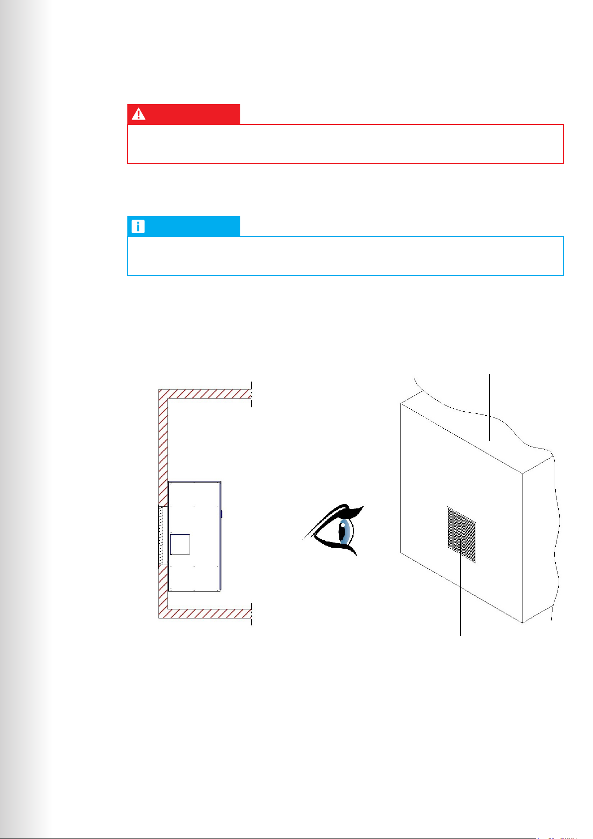
5.1.Positioning and mechanical installation..............................................................................................18
5.2.Electrical connections ..............................................................................................................................20
6.Start-up ...............................................................................................................22
6.1.Controller setting........................................................................................................................................22
6.2.Functional checks ......................................................................................................................................22
6.3.Other tests (facultative)............................................................................................................................23
6.4.Shutdown ......................................................................................................................................................23
7.Maintenance ........................................................................................................24
7.1.Safety instructions .....................................................................................................................................24
7.2.Preventative maintenance schedule ...................................................................................................24
7.3.Cleaning / replacement of components ............................................................................................25
7.4.General appliance cleaning procedures.............................................................................................25
8.Information on residual hazards and emergency situations.................................26
8.1.General safety provisions ........................................................................................................................26
8.2.Hazards arising from the product coming into contact with things or persons....................26
8.3.Hazards arising from electrical faults..................................................................................................26
8.4.Fire hazards and toxic substances.......................................................................................................27
9.Uninstalling and disposal of the unit ...................................................................28
10.Technical data and drawings .............................................................................29

6
FREEAIR3IN
EN/02.2018 © STULZ SpA – all rights reserved
IMPORTANT
These operating instructions are to be read carefully and complied with before installing and
operating the unit.
Keep this manual for the whole life period of the unit, inside the shelter or together with any other
literature concerning the equipment which utilizes the product, provided it is a dry and clean
place.
This manual reflects the state of the art existing at the time the product is marketed and shall not
be deemed to be inadequate for the sole reason that it has not been updated as a result of any
new experience.
STULZ reserves the right to update the product and relevant manual without being required to
update previous products and manuals other than in exceptional circumstances.
To require or receive any updates of the instructions manual or amendments thereto, which shall
be deemed to be an integral part of the manual, please contact your local STULZ partner.
It is absolutely essential to comply with the measures listed in chapter "Safety directions".

7
FREEAIR3IN
© STULZ SpA – all rights reserved EN/02.2018
1. Safety directions
This manual contains the basic instructions which must be respected during installation, use and
maintenance of the unit. Therefore, installer and specialized personnel / user must read and respect
these indications before mounting and commissioning the unit.
DANGER
Read carefully the whole information on this manual, with particular attention to the norms
marked with the symbol on the left. Failure of conformity to these norms might cause damages
to things, people, ambient and the unit itself.
The manufacturer is not responsible for any misuse of unit, as well as for non-authorized
modifications and for the inobservance of instructions on this manual.
INFORMATION
This manual must be kept by the customer and made available to the installation,
commissioning, use and maintenance personnel.
Symbols on this manual:
DANGER RISK OF INJURY FOR OPERATOR AND
POSSIBILITY OF DAMAGING THE UNIT
ATTENTION INFORMATION OR WARNING OF CAUTION
IN CARRYING OUT A PROCEDURE
INFORMATION IMPORTANT INFORMATION
1.1. Personnel qualification and training
Personnel in charge of installation, use, maintenance, inspection and monitoring must be qualified
correspondingly.
1.2. Danger in case of failure to comply with safety instructions
Failure to comply with safety instructions might cause danger to the personnel, as well as to the
environment and the unit. In addition, it entails loss of compensations rights.
1.3. Work in safety
Observe safety instructions in this operating instruction manual, national regulations about accident
prevention and internal safety, operational and working indications.

8
FREEAIR3IN
SERIE - SERIES - SERIE - SERIE
ORDINE - ORDER - BESTELLUNG - COMMANDE
DATA - DATE - DATUM - DATE
UNITA' DI FREE COOLING - FREE COOLING UNIT
GERÄTE MIT FREIR KÜHLUNG - UNITES DE FREE COOLING
20/10/2016
--- kW ()
Tensione nominale - Rated voltage - Nennspannung - Tension
nominale
--- A
Resa nom. - Cooling cap. - Kaelteleistung-
Puissance nominale
MODELLO - MODEL - TYP - MODELE N°
OP:
Fusibile di sicurezza tipo aM - Safety fuse type aM -
Sicherungstyp aM - Fusible de securite type aM --- A
MADE IN ITALY
48 V
Marcia - Run current -
Nennstrom - Marche
-20/45
Temp. esterna -Exterior temp. - Umgebungsluft Temp. - Temp. ext.
75 kg
Peso - Weight - Gewicht - Poids
--- kW ()
Potenza Assorbita - Input power - Leistungsaufnahme -
Puissance absorbee
Grado di Protezione IP - Degree of protection IP - Schutzart IP -
Degré de protection IP IP X4
FCL700B112Z000 7035
EN/02.2018 © STULZ SpA – all rights reserved
1.4. Maintenance, inspection and monitoring of the plant
The operator must ensure that all maintenance, inspection and assembly work is carried out
by authorised and qualified specialist staff who have made an in-depth study of the operating
instructions. Before any intervention on the unit, refer to instructions on this manual, check data on
the name-plate and take any other precaution in order to guarantee optimal safety.
It is absolutely essential to comply with the procedure for shutting down the system described in the
operating instructions. Before maintenance work, the unit must be switched off at the main switch
and a warning sign displayed to prevent unintentional switching-on.
1.5. Independent conversion and manufacture of replacement parts
The system may only be converted or modified after consultation with STULZ. Original replacement
parts and replacement parts/accessories authorized by STULZ are an aid to safety.
1.6. Unacceptable operating methods
The operating safety of the system is only guaranteed when it is used as intended. The limit values
stipulated in the technical data must not be exceeded under any circumstances.
2. Unit identification
Technical name-plate
This unit can be correctly identified by the technical name-plate containing all information for its
correct use. This plate is positioned on the external casing of the unit (generally on one of its sides)
and on the cover of the electrical panel. An example follows:

9
FREEAIR3IN
© STULZ SpA – all rights reserved EN/02.2018
The technical data label is printed on a plastic surface to ensure long durability of the text even in the
toughest room conditions.
ATTENTION
For any assistance or information concerning the unit described in this manual, knowledge of its
serial number is essential.
IP protection degree
INFORMATION
IP protection degree is the protection, from the outdoor environment, of the unit when installed
in its normal use.
The IP protection degree of STULZ Free-Air-3IN unit, installed with suitable external rainproof
grille, is IPX4, therefore the unit is protected from harmful effects of splashing of water against the
enclosure from any direction (according to EN 60529, considering the prescriptions of EN 60335).
For more information please contact your local STULZ partner.
Outdoor Indoor
Unit with rainproof grille
Shelter wall

10
FREEAIR3IN
FCL 70 0 B 1 12 N 000
EN/02.2018 © STULZ SpA – all rights reserved
Type code
Product family
Nominal cooling capacity
Working modes
Control type
Application
Main power supply
Compressor - refrigerant
Heating
Combination of options
0 = no heating
N = no compressor
12 = 48 V DC
1 = inside the room to be conditioned
B = electronic I/O controller C102
0 = free cooling only
70 = 7 kW (with T 5°C)
FCL = Free-Air-3 unit
INFORMATION
Special models are identified with a Z on the 11th digit of the code. Last 3 digits after Z loose
their original meaning, as they are the progressive number to identify special versions.
3. Components and operating
principle
3.1. Intended and non-intended use
Intended use
STULZ Free-Air-3IN units are designedfor cooling shelters / rooms suitablyprotectedfromweather.
Their use allows to eliminate problems caused by high internal temperatures. STULZ Free-Air-3IN
units have to be installed internally on the wall of the shelter or cabinet to be conditioned, whose
internal side is not accessible to the general public (see DIN EN 60335240, paragraph 3.119).

11
FREEAIR3IN
© STULZ SpA – all rights reserved EN/02.2018
INFORMATION
To get a cooling effect from Free-Air-3IN working, it is absolutely necessary that outside
temperature is lower than inside temperature.
Free-Air-3IN units must not be installed and used in other positions than the one for which they
have been designed. STULZ is not liable for any damage resulting from non-compliant installations.
The operator bears the entire risk.
Non-intended use
The unit cannot be installed on movable, vibrating, oscillating, tilted (non-levelled) parts.
Generally, unit cannot be installed in the following areas:
• With strong heat radiation
• With strong magnetic fields
• With free flames
• With fire risk
• With inflammable products
• With explosive atmosphere
• With saline atmosphere
• With aggressive atmosphere
For any doubt, please consult the manufacturer.
With Free-Air-3IN units the following site configurations are possible:
1. FCL stand-alone
• Free cooling made by FCL. Working logic: FCL control (C102)
2. FCL + one electrical heating connected to FCL
• Free cooling made by FCL. Working logic: FCL control (C102)
• Electrical heating. Working logic: on-off control by FCL (C102)
3.2. Component lay-out
External fresh air intake is from the rear side of the unit. Sucked by the fans, situated in the upper
and in the lower part of the unit, air passes through the filter, located immediately after the fresh air
intake opening. Air discharge grilles are located after the fans in the frontal side of Free-Air-3IN.
Electrical and control components, as well as electronic controller and connectors of I/O to the
controller, are located inside a separate box behind the frontal panel. The keypad, connected to
the electronic controller, is located on the frontal panel and it displays information about operating
conditions, the state of the unit and alarms. Holes for power supply, probe and signal cables, are on
the right side of the roof of the unit.

12
FREEAIR3IN
EN/02.2018 © STULZ SpA – all rights reserved
Airflow
Electrical Box
Fan
Fan
Air Filter
Keypad

13
FREEAIR3IN
© STULZ SpA – all rights reserved EN/02.2018
3.3. Working modes
Free cooling
When enabled by the electronic controller, the fans inside Free-Air-3IN unit suck external air and
blows it directly into the room to be conditioned.
Fresh air flow is regulated by the electronic controller modulating fan speed.
3.4. Mechanical components
Casing
These machines are built using self-supporting panels made of painted galvanised sheet metal
to guarantee good corrosion resistance (not suitable for corrosive and saline environments). They
make the machine easy to inspect and, at the same time, offer adequate protection to its internal
components. The external panels are internally lined with a 3 mm layer of sound-absorbing material.
Fan boxes, in the upper and lower part of the unit, are internally lined with a 10 mm layer of sound-
absorbing material.
Internal components are accessible by removing frontal panel, extracting its fastening screws with
suitable tools.
Air filter
Air filter belongs the filter class G4, zig-zag type to increase the surface until 0,85 m2. It is designed to
prevent large dirt particles present in the environment from entering the internal ambient.
3.5. Motors
Fan
The fans are radial EC centrifugal type, single-intake, with rotor painted in black. The degree of
protection is IP42 and insulation class B.
3.6. Control, monitoring and safety components
All equipment is set and inspected atthe factoryand generally does not require furtheradjustments or
interventions. If, for specific reasons, it becomes necessary to perform modifications on the settings
of automatic devices, this task must only be performed, subsequent to notification to the STULZ
engineering service, by specialized product expert. STULZ units are equipped with a set of devices
designed to ensure proper operation. Intervention by any one of these automatic safety devices is a
sign of a malfunction and it is absolutely necessary to eliminate the cause of the malfunction.
DANGER
It is prohibited to make electrical by-passes on safety equipment. This intervention, in addition to
being dangerous, also immediately invalidates guarantee coverage for the product.
Interrupt electrical power to the unit before performing any repair or maintenance.
Work on the unit must only be done by expert, qualified and authorized personnel.
Automatic circuit breaker of the fan
It protects against short circuits and excessive motor current. They have adjustable thermal and
magnetic triggering devices.

14
FREEAIR3IN
EN/02.2018 © STULZ SpA – all rights reserved
Temperature probes
2 PTC temperature probes are supplied loose with screened cables 8 m long and must be
connected to the C102 controller, in order to measure following parameters:
• Internal air temperature: shipped loose with screened cable 8 m long;
• •External air temperature mounted inside the unit.
STANDARD COMPONENTS WITH FREE-AIR-3-IN
Electronic controller C102
This microprocessor-based I/O controller is equipped with a set of terminals which are necessary
to connect the board to the controlled devices (e.g. valves, compressors, fans). The program,
composed of a software version with working logic and of a file with the value of parameters, is
written in the EEPROM, so that it is permanently stored even in case of power failure. C102 is
housed inside the electrical panel and can control one Free-Air-3IN unit. A keypad is connected to
C102 to display working conditions, working state of the unit and possible alarms.
INFORMATION
For controller input / output assignation, please refer to the electrical diagram included in part 2
manual, specific of each unit.
RFS dirty filter pressure switch
This gives a dirty filter signal, shown both on the display and on a voltage-free contact. It indicates
when it is necessary to clean or replace the air filter.
Range : 50 – 500 Pa
Differential pressure: 20 Pa + 15%
P1 : High pressure connection
P2 : Low pressure connection
Adjustment:
Use a screwdriver on the central screw to adjust the differential
pressure to the desired value at which the dirty filter signal trips.

15
FREEAIR3IN
© STULZ SpA – all rights reserved EN/02.2018
Technical characteristics:
Power supply: 1.0 (0.4) A; 250 Vac
Operating temperature: -20/+85°C
Maximum pressure: 10 kPa
Contacts: Microswitch with AgCdO (on/off) contacts.
Material: Switch body Pa 6.6 Plastic PS
Protection: IP00
Diaphragm: Silicone
Pressure connection: ø 6 pipe
Connection :
Contact 31 opens when the differential pressure exceeds the preset value.
At the same time contact 32 closes. The signal is transmitted through this
contact.

16
FREEAIR3IN
EN/02.2018 © STULZ SpA – all rights reserved
4. Unpacking and inspection
INSPECTION
STULZ products are delivered ex-works. All units have been individually inspected in all their
components and been carefully packaged before of the delivery.
Immediately inspect the unit upon receipt of the goods:
• Make sure that it has been transported in the correct position. Note any unsuitable shipping
condition on the shipping document.
• Check that no components are missing, that are presents on shipping document and the integrity
of the unit at the moment of the receiving.
• Check that there aren’t any external damages. In case, note them on the shipping document in the
presence of deliverer.
• Hidden damages, that are verified after removal the packing, must always be notified to the
shipper by registered letter within 8 days of receipt of the goods.
INFORMATION
With ex works delivery conditions, carrier is the sole responsible for any damage caused during
transport. STULZ is not responsible for damages to the goods caused by the carrier, but it will
do everything in its power to assist clients on those situations.
If delivery conditions are not ex works, in case of damage, please follow instructions either on
transport document or on www.stulz.it web site.
This product cannot be returned without prior approval of STULZ. For any assistance, please
consult your local STULZ partner.
4.1. Lifting and transport
This unit doesn’t need particular precautions for transport. When more units are packed together on
a pallet, use a fork lift, taking care that the centre of gravity is inside fork area.
DANGER
Capacity of lifting device must be appropriate for the weight of the unit.
Load must be balanced to avoid tilting.
Avoid offhanded or rough manoeuvres.
Don’t lay other objects upon the unit.

17
FREEAIR3IN
© STULZ SpA – all rights reserved EN/02.2018
4.2. Storage
Except differently agreed, standard packing of units is composed of: a pallet under the unit, fixed to
its lower frame, protective film around the surface (except bottom side in contact with the pallet) and
air bag on the upper part.
INFORMATION
Standard packing doesn’t protect the unit from rain and bad weather.
Standard packing is not suitable for seafreight.
Standard packing is not suitable for airfreight
Following information can be found on packing:
• STULZ logo
• Unit code
• Accessories put in the packing
• Warning symbols
If unit is stored before installation, comply with following instructions:
• Don’t expose to direct solar radiation
• Store the unit with its original packing
Ambient conditions for storage are the following:
• Ambient temperature min / max = -20°C / +60°C
• Max humidity RH 90%
4.3. Removal of packing
• Remove packing without damaging the unit: remove top air bag, external film, lateral and corner
protections
• Recover any document or component inside the packing
• Keep original packing (pallet and protections) for future shipments
ATTENTION
Use original packing to ship the unit to any other destination.
If packing disposal is necessary, we remind to dispose different materials suitably (see chapter
"9. Uninstalling and disposal of the unit").
5. Installation
DANGER
Never work on the unit without disconnecting all power supplies before. Prior to drilling holes or
making cuts on the cabinet, make sure that holes, screws, cables, etc. do not interfere with the
equipment which has already been installed.

18
FREEAIR3IN
EN/02.2018 © STULZ SpA – all rights reserved
5.1. Positioning and mechanical installation
1. Free-Air-3IN units must be installed inside the room to be conditioned.
2. Check that:
• There is space enough for an easy application, installation and maintenance; it is necessary to
have a minimum distance from the floor of 200 mm and also from the top of the unit of 200 mm.
In particular, a minimum distance of 1000 mm from the unit has to be considered both inside
and outside the ambient to be conditioned.
• The wall or door where the unit has to be fixed can support its weight;
• The room to be conditioned is clean inside;
• The unit is not in the proximity of heat sources or warm air flows;
• The structure is water tight;
• The inside of the room allows a proper air circulation, preventing any recirculation;
• If it is installed on a door, make sure that the hinges are strong enough to support the unit. Make
sure that the electric cable does not get torn or damaged when the door is closed. If the depth
of the Free-Air-3 prevents the door from being completely opened, arrange a stopper for such a
door.
3. Two openings are required on the walls
• One is for fresh air intake. This opening, of 660mmx540mm, must be made according to the
relevant cut-out shown below.
• The other opening is for exhaust air discharge. It should be placed in a position which allows
a good air circulation during free cooling, avoiding short circuits of air and allowing fresh air to
reach the relevant points to be cooled. A suitable overpressure damper must be installed on the
second opening, to avoid internal air going out from it during operation of the units.
Cut-out of Free-Air-3IN unit (view of the installation wall from outside)

19
FREEAIR3IN
© STULZ SpA – all rights reserved EN/02.2018
4. After making openings on room walls, protect them against water (rain) infiltrations suitably.
5. Glue the adhesive gasket (supplied with the unit) around the edge of the air openings drilled on
the wall. Gasket is made of ethylene-propylene, open cell, with 3 mm thickness and 10 mm width.
6. Place the FCL against the wall so that openings on its rear side correspond to the cut-out on
the wall. Then, secure it with M6 screws and the supplied fixing bracket as it is shown below.
Generally the installation is realized with two horizontal fixing bracket, but it is possible to perform
a lateral fastening using fixing bracket (on request) to be applied on the fixing holes on the later
side of the unit and into the wall.
ATTENTION
Do not block off circulation of air intake and/or expelled by the Free-Air-3IN.
Fixing bracket with L shape
(supplied by STULZ)
Fixing bracket with L shape
(supplied by STULZ)

20
FREEAIR3IN
OUTDOOR
INDOOR
50 50
20
M6
M6
20
INDOOR OUTDOOR
EN/02.2018 © STULZ SpA – all rights reserved
5.2. Electrical connections
DANGER
It's absolutely necessary, before making any connections, to use a suitable tester to check the
voltage supply. This must be the same as the voltage indicated on the technical data plate.
The user must furnish and install, upstream from the unit, an omni-pole automatic switch with
capacity as specified on the technical data plate in order to be able to perform maintenance on
the unit in the absence of electricity.
The ON/OFF key on the C102 keypad is only used for the unit stand-by. Therefore, it must not
be considered as a safety element to perform maintenance on the unit. Maintenance must be
done after disconnecting the power supply of the unit (see note above).
Any signal cable (temperature probes, alarms, keypad) longer than 3 m must be screened
against electromagnetic disturbs.
Electrical connections have to be carried out only by authorized technical personnel.
Electrical wiring of this unit must be executed in compliance with following norms:
• Machinery Directive (2006/42/EEC – 98/37/EEC)
• Low voltage (2006/95/EEC)
• Electromagnetic compatibility (2004/108/EEC)
• National rules for technical plants
1. Check the supply voltage and verify if it is within the admitted range of the unit.
2. Interrupt power supply before working on the system: make sure that the main switch is turned
off and the system is isolated from power mains; make sure also that all power switches and
control fuses in the electric system have been turned off.
Table of contents