Subzero Wolf UC Series User manual

UC-24C Component Access & Removal 64
subzero.com 800.222.7820
UC Series
Service Manual

Page 2
7-13 #7031931 - Revision A - June, 2014
MODEL UC-24C
Figure 7-28. Kickplate Removal
MODEL UC-24C EXTERIOR COSMETIC AND MECHANICAL COMPONENTS
Kickplate (Model UC-24C)
To remove the kickplate, extract the mounting screws
located at each end of the kickplate and pull the kick-
plate forward. (See Figure 7-28)
Door Switch and Switch Box Bracket Assembly
(Model UC-24C)
The door switch is inserted through the hole in the
switch box bracket assembly Magnet and tabs on the
sides of the switch hold the switch in place. The
assembly is attached to the bottom of the cabinet with
screws.
To remove the switch and switch box bracket assembly
(See Figure 7-30):
1. Extract switch box bracket assembly mounting
screws.
2. Pull assembly down, then rotate back to front.
3. Disconnect electrical leads from switch.
4. Depress tabs on side of switch while pushing switch
out of hole.
Door Gasket (Model UC-24C)
An extruded dart at the back of the door gaskets is
pressed into retaining channels that are molded into
door liner.
To remove the door gasket, pull the gasket from the
retaining channels (See Figure 7-31).
Figure 7-30. Light Switch & Switch box
Screws (2)
Bracket
Switch
UNDER COUNTER SERIES
UNDER COUNTER SERIES (SWS #3603000)
(SWS #3603000) Component Removal
Kickplate
Mounting Screw
(1 of 2)
Figure 7-31. Gasket Removal
Door Gasket
Channel

Page 3
7-14
#7031931 - Revision A - June, 2014
Component Removal UNDER COUNTER SERIES
UNDER COUNTER SERIES (SWS #3603000)
(SWS #3603000)
Door Shelf Components (Model UC-24C)
The door shelf retainer fits into notches in the retainer
clips that are attached to the door dikes with screws.
To remove the door shelf components (See Figure 7-
32):
1. Flex shelf retainer outward in the middle, disengag-
ing it from retainer clips.
2. Extract retainer clip mounting screws and pull
retainer clip from dike.
Door Assembly (Model UC-24C)
NOTE: When removing a model UC-24C from its
installation, an anti-tip bracket and a countertop bracket
should have been used to make a solid installation.
After pulling unit approximately 6” out from its installa-
tion (See Figure 7-33):
1. Open door.
2. Extract screws from top cabinet hinge.
3. Lift door with bottom door hinge pin out of the bot-
tom cabinet hinge.
Figure 7-33. Door Removal
Cabinet Hinge
Mounting Screws
Figure 7-32. Door Shelf Removal
Retainer Clips
Shelf Retainer

Page 4
7-15 #7031931 - Revision A - June, 2014
UNDER COUNTER SERIES
UNDER COUNTER SERIES (SWS #3603000)
(SWS #3603000) Component Removal
MODEL UC-24C INTERIOR COSMETIC AND MECHANICAL COMPONENTS
Wine Rack Assembly (Model UC-24C)
To remove a wine rack assembly (See Figure 7-34):
1. Pull rack forward until it stops.
2. Lift front of rack up while continuing to pull forward.
3. After indentations on the wine rack clear the rollers
on the cabinet slides, lower front of rack while con-
tinuing to pull forward and lifting rear of rack.
Cantilever Shelf (Model UC-24C)
The cantilever shelf has hooks at the back of each side
rail that hook into the slots of the shelf ladders that are
attached at the back left and right corners of the cabi-
net.
To remove the cantilever shelf, lift it up at the front, then
lifting the hooks at the back up and out of the shelf lad-
der slots (See Figure 7-35).
To reinstall, tilt the front of the shelf up, align the hooks
at back with the slots in shelf ladders, then insert hooks
into slots and lower front of shelf.
Cabinet Slide and Support Spacer
(Model UC-24C)
Cabinet slides are attached to the side walls with
screws. If on the hinge side of the compartment, a
wide plastic support spacer is attached between the
slide and the wall.
To remove a cabinet slide, extract the mounting screws
and pull the slide and support spacer from the wall (See
Figure 7-36).
Figure 7-36. Cabinet Slide & Support Spacer
Figure 7-34. Wine Rack Removal
Figure 7-35. Cantilever Shelf Removal
Slide
Support Spacer

Page 5
7-16
#7031931 - Revision A - June, 2014
Component Removal UNDER COUNTER SERIES
UNDER COUNTER SERIES (SWS #3603000)
(SWS #3603000)
Ice Bucket (Model UC-24C)
To remove the ice bucket, grab the handle that is mold-
ed into the bottom front of the bucket and pull bucket
forward (See Figure 7-37).
Refrigerator Liner Cover (Model UC-24C)
Screws pass though the refrigerator liner cover into the
rear wall, securing the cover to the rear wall. The liner
cover is further secured by slots in its side flanges fitting
over pegs at the bottom of each shelf ladder.
NOTE: The refrigerator compartment thermistor passes
through a key-hole slot in the refrigerator liner cover
and is attached to the side wall with a screw and P-
clamp.
To remove the refrigerator liner cover (See Figure 7-
38):
1. Extract the mounting screws.
2. Lean top of refrigerator liner cover forward slightly
and work the compartment thermistor wire out of
the key-hole slot.
3. Continue leaning top of refrigerator liner cover for-
ward, then lift it up off of locator pegs at the bottom
of each shelf ladder
Refrigerator Compartment Thermistor
(Model UC-24C)
The refrigerator compartment thermistor is attached to
the refrigerator compartment right side wall, just below
the cabinet slide, with a screw and P-clamp. The ther-
mistor wires run direct to the electronic control board.
To remove a compartment thermistor, first remove the
refrigerator liner cover, then (See Figure 7-39):
1. Extract P-clamp mounting screw and pull thermistor
body from P-clamp.
2. Cut thermistor wire leads six (6) to twelve (12) inch-
es (152 mm - 305 mm) from the point where they
enter the compartment, then pull thermistor from
compartment.
Figure 7-37. Ice Bucket Removal
Figure 7-38. Refrigerator Liner Cover Removal
Refrigerator
Liner
Cover
Ice Bucket
Figure 7-39. Refrigerator Compartment Thermistor
Refrigerator
Compartment
Thermistor

Page 6
7-17 #7031931 - Revision A - June, 2014
UNDER COUNTER SERIES
UNDER COUNTER SERIES (SWS #3603000)
(SWS #3603000) Component Removal
Shelf Ladders (Model UC-24C)
The shelf ladders are attached to the side walls with
screws.
To remove a shelf ladder, first remove the refrigerator
liner cover. Then, extract the shelf ladder mounting
screws and pull the shelf ladder away from side wall
and out of compartment. (See Figure 7-40)
Compartment Light Bulb & Socket (Model UC-24C)
The compartment light bulb and socket are in the ceil-
ing of the compartment. Tabs at the back of the socket
hold it in the light bracket (See Figure 7-41).
Light Bulb Removal
Turn light bulb counterclockwise to remove it; clock-
wise to install it.
Light Socket Removal
Pull light socket from hole in bracket, then discon-
nect electrical leads.
NOTE: This may break the tabs on the back of the
socket, but since it should only be removed in order
to replace it, this should not matter. If not removing
it in order to replace it, then drill out the heads of
the rivets holding the bracket in place, lower the
bracket down, then depress the tabs on the side of
the socket while pushing it out of the bracket.
Control Panel/Display Assembly (Model UC-24C)
The control panel/display assembly is attached at the
top front of the mullion assembly by screws passing up
from beneath the mullion into screw grommets that are
molded into the display assembly. A wire cover is
attached to the bottom of the mullion assembly with
plastic rivets to protect the control cable.
To remove the control panel/display assembly, (See
Figure 7-42):
1. Use a fingernail, putty knife, or similar device to
extract the plastic rivet center posts, then pull rivets
out and drop wire cover from bottom side of mullion
assembly.
2. Disconnect display electrical leads at bottom side of
mullion assembly.
3. With a phillips-head screwdriver, extract control
panel mounting screws.
4. Lift assembly up, feeding wire leads up through
access hole.
Figure 7-42. Control Panel/Display Assembly
Figure 7-40. Shelf Ladder Removal
Figure 7-41. Compartment Light Bulb / Socket
Light Socket
Light Bulb
Bracket
Shelf Ladders
Control
Panel
Assembly
Wire
Cover

Page 7
7-18
#7031931 - Revision A - June, 2014
Component Removal UNDER COUNTER SERIES
UNDER COUNTER SERIES (SWS #3603000)
(SWS #3603000)
Icemaker Assembly (Model UC-24C)
The icemaker assembly is attached to the right side of
the evaporator cover with screws, two at the top of the
icemaker and one at the bottom.
To remove the icemaker assembly, (See Figure 7-43):
1. Extract icemaker mounting screws.
2. Pull icemaker forward and to the left, then remove
icemaker head cover.
3. Disconnect icemaker electrical leads, then pull ice-
maker out of compartment.
Freezer Air Duct (Model UC-24C)
The freezer air duct is attached to the right side wall
with screws passing through it into screw grommets.
The rear of the air duct has flanges that hook into slots
in the evaporator cover.
To remove the freezer air duct, first remove the icemak-
er assembly, then (See Figure 7-44):
1. Extract the front mounting screws.
2. Pull front of air duct toward the left and unhook the
rear flanges from the slots in the evaporator cover.
Mullion Assembly (Model UC-24C)
The mullion assembly sits on supports at each side
wall. Plastic rivets at the front bottom corners, along
with the refrigerator liner cover sitting on the top rear of
the mullion assembly hold it in place.
To remove the mullion assembly, (See Figure 7-45):
1. Use a fingernail, putty knife, or similar device to
extract the plastic rivet center posts at each corner
and along front of wire cover, then pull rivets out
and drop wire cover from bottom side of mullion
assembly.
2. Disconnect display electrical leads at bottom side of
mullion assembly.
3. Pull mullion assembly forward, out of compartment.
Figure 7-45. Mullion Assembly Removal
Figure 7-43. Icemaker Assembly Removal
Figure 7-44. Freezer Air Duct Removal
Mullion
Assembly
Screw
Screws
Icemaker
Freezer Air Duct

Page 8
7-19 #7031931 - Revision A - June, 2014
UNDER COUNTER SERIES
UNDER COUNTER SERIES (SWS #3603000)
(SWS #3603000) Component Removal
Defrost Terminator (Model UC-24C)
The defrost terminator is attached to the evaporator out-
let.
To remove the defrost terminator, the mullion assembly
must be removed first, then (See Figures 7-46):
1. Disconnect terminator wire leads from wire harness.
2. Pull terminator off of tubing.
Freezer Evaporator Cover (Model UC-24C)
The evaporator cover has slots at the bottom of its side
flanges that fit over pegs that are attached to the side
walls. Screws passing through the front of the evapora-
tor cover secure it to the evaporator brackets and evap-
orator fan bracket.
To remove the freezer evaporator cover, first remove
the mullion assembly, icemaker assembly and freezer
air duct, then (See Figure 7-47):
1. Extract the evaporator cover mounting screws.
2. Pull top front of evaporator cover forward and lift off
of pegs.
3. Remove compartment thermistor and control cable
out of top key-hole slot, as well as icemaker wire
leads from lower right front access hole.
Freezer Compartment and Evaporator Thermistors
(Model UC-24B)
The freezer compartment thermistor is attached to the
freezer compartment right side wall, behind the freezer
air duct, with a screw and P-clamp. The evaporator
thermistor is attached to the evaporator with a screw
and P-clamp. The wiring of both thermistors runs direct
to the electronic control board.
To remove a freezer compartment or evaporator ther-
mistor, first remove the mullion assembly, icemaker
assembly, freezer air duct and evaporator cover, then
(See Figure 7-48):
1. Extract P-clamp mounting screw and pull thermistor
body from P-clamp.
2. Cut thermistor wire leads six (6) to twelve (12) inch-
es (152 mm - 305 mm) from the point where they
enter the compartment, then pull thermistor from
compartment.
Figure 7-47. Freezer Evaporator Cover Removal
Figure 7-48. Freezer Thermistors
Figure 7-46. Defrost Terminator Removal
Evaporator Cover
Thermistors
Defrost Terminator

Page 9
7-20
#7031931 - Revision A - June, 2014
Component Removal UNDER COUNTER SERIES
UNDER COUNTER SERIES (SWS #3603000)
(SWS #3603000)
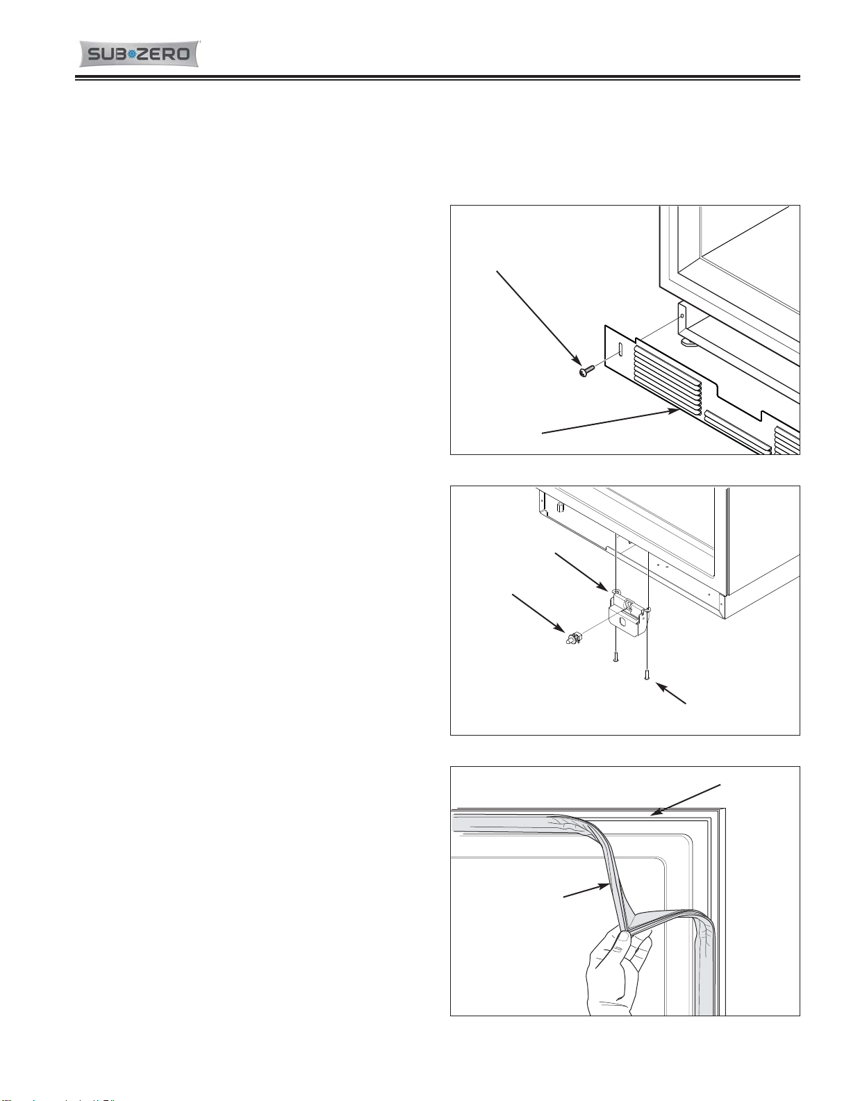
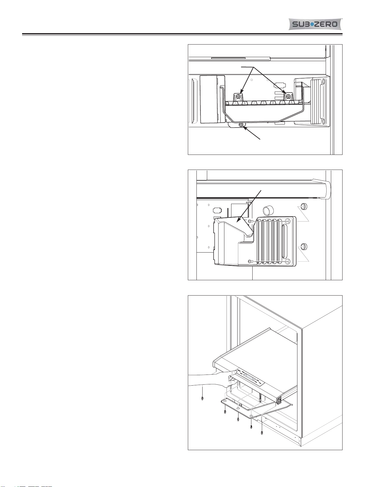
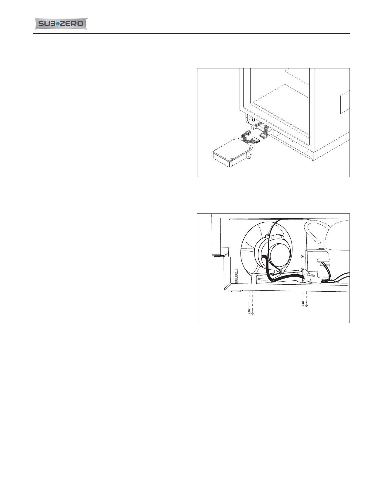
Evaporator Fan Assembly (Model UC-24C)
Screws pass through the rear bracket of the evaporator
fan assembly, as well as the baffle control assembly,
into screw grommet/stand-offs to secure the fan
assembly the back wall.
To remove the evaporator fan assembly, first remove
the mullion assembly, icemaker assembly, freezer air
duct and evaporator cover, then (See Figure 7-49):
1. Disconnect fan motor electrical leads.
2. Extract fan assembly mounting screws.
2. Pull assembly forward, out of compartment.
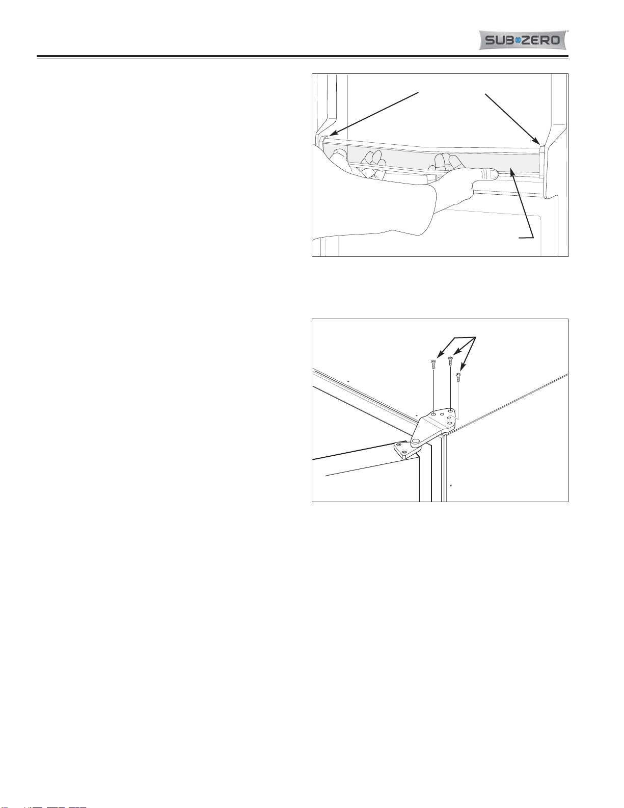
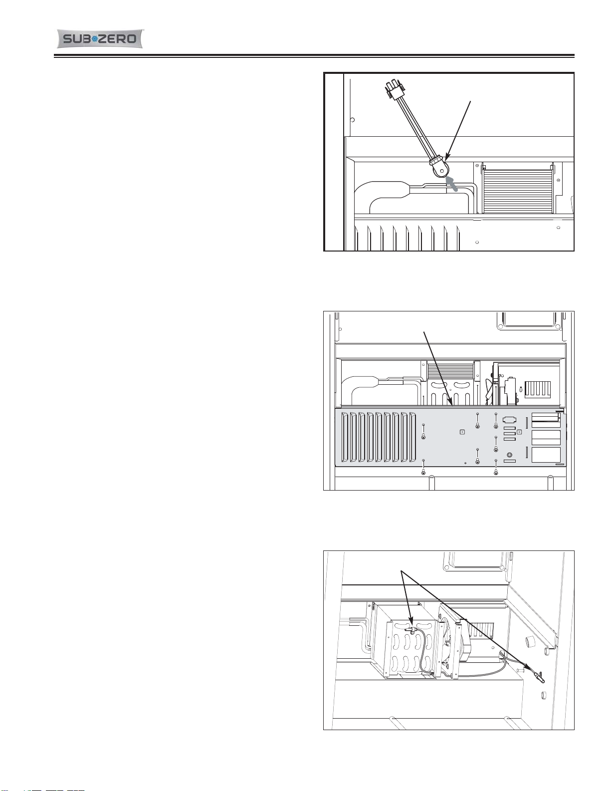
Baffle Control Assembly (Model UC-24C)
Screws pass through the rear bracket of the evaporator
fan assembly and the baffle control assembly, into
screw grommet/stand-offs to secure them to the back
wall.
To remove the baffle control assembly, first remove the
mullion assembly, icemaker assembly, freezer air duct,
evaporator cover and evaporator fan assembly, then
(See Figure 7-50):
1. Disconnect baffle control assembly electrical leads.
2. Pull assembly forward, off of screw grommet/stand-
offs and out of compartment.
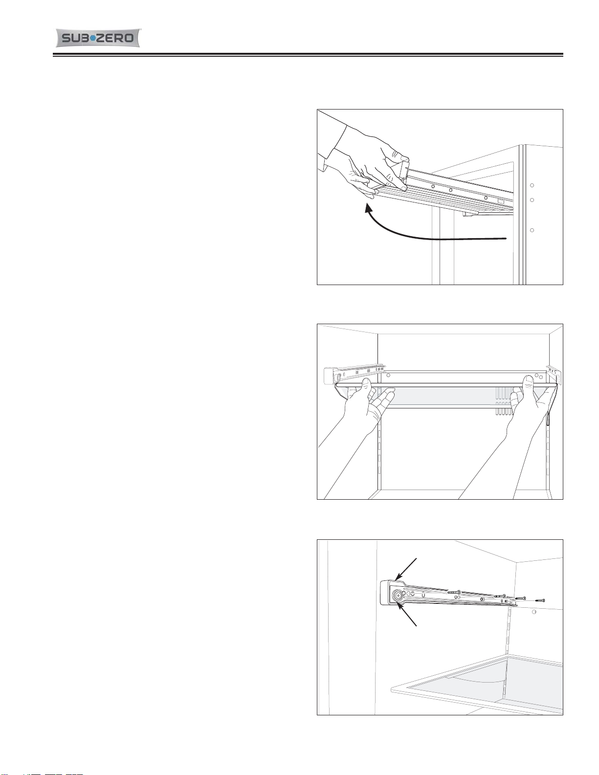
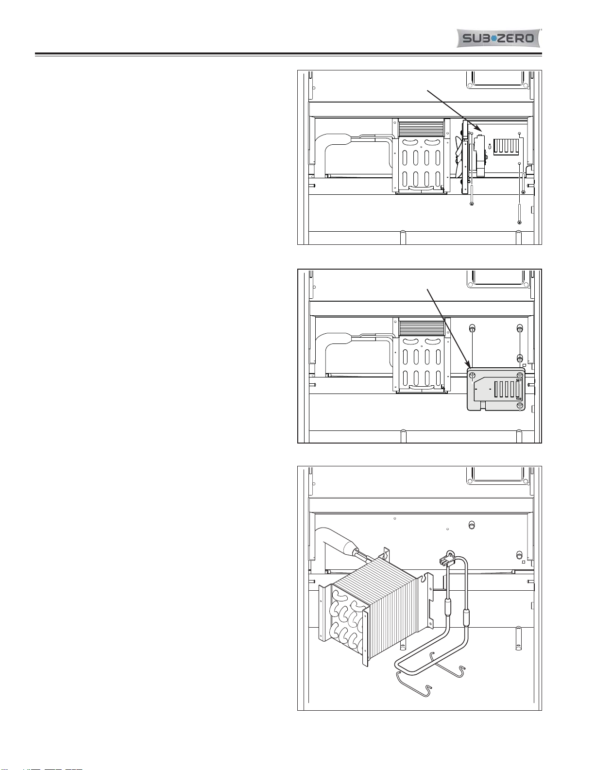
Defrost Heater Assembly (Model UC-24C)
The defrost heater is held to the bottom of the evapora-
tor with heater clips.
To remove the defrost heater assembly, first remove the
mullion assembly, icemaker assembly, freezer air duct
and evaporator cover, then (See Figure 7-51):
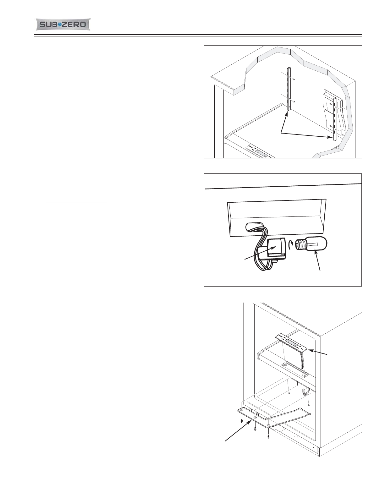
1. Disconnect defrost heater electrical leads.
2. Extract evaporator mounting screws and pull evap-
orator forward and toward the left.
3. Slide defrost heater toward the rear of the evapora-
tor.
NOTE: It may be necessary to remove the defrost
heater clips with a needle-nose pliers in order to
remove the defrost heater.
Figure 7-51. Defrost Heater Removal
Figure 7-50. Baffle Control Assembly Removal
Figure 7-49. Evaporator Fan Assembly
Evaporator Fan Assembly
Baffle Control Assembly

Page 10
7-21 #7031931 - Revision A - June, 2014
UNDER COUNTER SERIES
UNDER COUNTER SERIES (SWS #3603000)
(SWS #3603000) Component Removal
MODEL UC-24C UNIT TRAY MECHANICAL COMPONENTS
Main Control Board Assembly (Model UC-24C)
The control board assembly sits at the front left side of
the unit tray, held in place with dual-lock fasteners,
which is similar to velcro.
To remove the main control board assembly, first
remove the kickplate, then (See Figure 7-52):
1. Lift control assembly up to separate the dual-lock
fasteners.
2. Pull control assembly forward to expose wire har-
ness electrical connectors at back of control assem-
bly, then disconnect the wire harnesses.
Condenser Fan Assembly (Model UC-24C)
The condenser fan motor is secured to the condenser
bracket with screws. The bracket is secured at the
back of the unit tray by screws passing up from under
the unit tray into threaded stand-offs.
To remove the condenser fan assembly, the appliance
will need to be removed from it’s installation in order to
access the fan from the rear.
NOTE: If removing a Model UC-24C from its installa-
tion, an anti-tip bracket and a countertop bracket may
have been used to make a solid installation.
After pulling the appliance from its installation, (See
Figure 7-53):
1. Remove unit cover from bottom back of appliance.
2. Disconnect fan motor electrical leads.
3. Extract grounding screw.
4. Carefully lean appliance toward side and extract
bracket mounting screws, then lift assembly from
unit tray.
Figure 7-52. Main Control Board Assembly
Figure 7-53. Condenser Fan Assembly Removal

Page 11
7-22
#7031931 - Revision A - June, 2014
Component Removal UNDER COUNTER SERIES
UNDER COUNTER SERIES (SWS #3603000)
(SWS #3603000)
Water Valve (Model UC-24C)
The quick-connect water valve is attached to a flange
that is part of an air baffle that is attached to the unit
tray.
NOTE: To remove the water valve, the appliance must
be pulled from its installation. When removing an
Under Counter appliance from its installation, keep in
mind that an anti-tip bracket and a countertop bracket
may have been used to make a solid installation.
NOTE: Turn off water supply before attempting this
repair.
To Remove the water valve (See Figures 7-54 and 7-
55):
1. Remove access panel from bottom back of unit and
door closer from bottom front corner.
2. Extract screws securing unit tray to cabinet on the
left side, and loosen screws on right side.
3. Separate cabinet from unit tray by leaning cabinet
to the right, then insert a spacer between cabinet
and unit tray (a piece of 2x4 lumber works well).
4. Disconnect valve electrical leads.
5. Extract valve mounting screws.
6. Disconnect water tubes from valve by pushing col-
lar around tube toward valve, while pulling water
tube away from valve.
NOTE: Water tubing attached to a quick-connect water
valve may develop indentations around the tubing
under the connection rings. To prevent leaks when
installing a new water valve, it may be necessary to cut
a new straight edge at the end of the water tube, if
indentations are present, before inserting it into a new
valve.
Figure 7-55. Water Valve Removal
Figure 7-54. Unit Tray Component Access
Loosen Screws
on this side
Remove Screws
on this side

Page 12
7-23 #7031931 - Revision A - June, 2014
MODEL UC-24C SEALED SYSTEM COMPONENTS
NOTE: To remove any sealed system component from an Under Counter appliance, the appliance must be pulled
from its installation. When removing an Under Counter appliance from its installation, keep in mind that an anti-tip
bracket and a countertop bracket may have been used to make a solid installation.
NOTE: Before attempting to remove a sealed system
component, evacuate the refrigerant from the sealed
system.
NOTE: Always replace the high-side filter-drier when
servicing the sealed system.
High-Side Filter-Drier (Model UC-24C)
To Remove the filter drier (See Figures 7-56 and 7-57):
1. Remove access panel from bottom back of unit and
door closer from bottom front corner.
2. Extract screws securing unit tray to cabinet on the
left side, and loosen screws on right side.
3. Separate cabinet from unit tray by leaning cabinet
to the right, then insert a spacer between cabinet
and unit tray (a piece of 2x4 lumber works well).
4. With the edge of a file, score a line around capillary
tube approximately one (1) inch (25 mm) from filter-
drier outlet.
5. Fatigue capillary tube at line just scored until it sep-
arates.
6. With a tube cutter, cut inlet tube approximately one
(1) inch (25 mm) from filter-drier.
NOTE: Sweating the joints apart is not recommended
as this may induce moisture into the sealed system and
could cause a solder restriction in the capillary tube.
NOTE: Check the end of the remaining capillary tube
for internal burrs. If burrs exist, rescore a line around
the capillary tube approximately one (1) inch (25 mm)
from the end and fatigue the capillary tube at this new
line until it separates.
NOTE: When installing the replacement filter-drier,
insert the capillary tube until it touches the screen, then
pull the capillary tube approximately 3/8” (9.5 mm)
away from the screen before brazing (See Figure 7-58).
When installing a new filter-drier, be sure to thoroughly
clean the tubing before brazing.
Figure 7-57. Drier Removal
Figure 7-56. Unit Tray Component Access
Loosen Screws
on this side
Remove Screws
on this side
Cut here
Cut here
Figure 7-58. Drier Installation
3/8”
(9.5 mm)
Cut-Away
Cut-Away
View of Drier
View of Drier
UNDER COUNTER SERIES
UNDER COUNTER SERIES (SWS #3603000)
(SWS #3603000) Component Removal

Page 13
7-24
#7031931 - Revision A - June, 2014
Component Removal UNDER COUNTER SERIES
UNDER COUNTER SERIES (SWS #3603000)
(SWS #3603000)
Evaporator (Model UC-24C)
The evaporator is attached to the rear wall with screws,
behind the evaporator cover.
To Remove the evaporator (See Figures 7-59):
1. Extract screws which hold evaporator to rear wall.
2. With a file, score a line around capillary tube, 1” (25
mm) or less from evaporator inlet, then fatigue cap-
illary tube at this line until it separates.
4. With a tube-cutter, cut evaporator outlet 1” (25 mm)
or less from suction line connection point.
NOTE: Sweating the joints apart is not recommended
as this may induce moisture into the sealed system and
could cause a solder restriction in the capillary tube.
NOTE: Check the end of the remaining capillary tube
for internal burrs. If burrs exist, rescore a line around
the capillary tube approximately 1” (25 mm) from the
end and fatigue the capillary tube at this new line until it
separates.
NOTE: Always replace the high-side filter-drier when
servicing the sealed system.
Compressor (Model UC-24C)
The compressor is located at the back of the unit tray.
To Remove the compressor (See Figures 7-60 & 7-61):
1. Remove access panel from bottom back of unit and
door closer from bottom front corner.
2. Extract screws securing unit tray to cabinet on the
left side, and loosen screws on right side.
3. Separate cabinet from unit tray by leaning cabinet
to the right, then insert a spacer between cabinet
and unit tray (a piece of 2x4 lumber works well).
4. Disconnect compressor electricals.
5. With a tube-cutter, cut suction tube and discharge
tube approximately 1-1/2" (38 mm) from compres-
sor.
6. Remove nuts from compressor mounting studs and
lift compressor off of mounting studs.
NOTE: Sweating the joints apart is not recommended
as this may induce moisture into the sealed system.
NOTE: Always replace the high-side filter-drier when
servicing the sealed system.
Figure 7-59. Evaporator Removal
Figure 7-61. Compressor Removal
Suction
Discharge
Compressor
Figure 7-60. Unit Tray Component Access
Loosen Screws
on this side
Remove Screws
on this side
Cut
This manual suits for next models
1
Other Subzero Freezer manuals