SRH pg. 2 WARNINGS
WARNING CAUTION
FIRE OR EXPLOSION HAZARD
Can cause property damage, severe injury or
death.
Read manual carefully before installing, or
servicing this equipment, or serious injury or
death may result.
Check minimum clearance to combustibles to
make certain that heater is in a safe location.
Combustible items located too close to the
heater could cause a serious fire hazard. In
storage areas, signs for maximum permissible
stacking height to maintain clearance from the
heater to combustible materials must be
posted adjacent to the heater thermostats or in
the absence of such thermostats in a
conspicuous location.
Operating the heater in an atmosphere
containing combustible dust or flammable
vapors is dangerous and may potentially result
in injury or death.
Heaters must be oriented in such a way as to
maintain minimum clearances to vehicles
parked underneath them.
This heater expands and contracts with each
cycle. The installation of the gas connection
and mounting hardware must accommodate
this movement; otherwise, a fire or explosion
hazard may occur.
This heater is equipped with an automatic
ignition and does not contain a pilot. DO NOT
attempt to light the burner manually, this could
result in serious personal injury or fire hazard.
MECHANICAL HAZARD
•DO NOT use high pressure to test the gas
pipes with the burner still attached. This will
cause damage to the controls within the
burner requiring them to be replaced.
If heater is being operated in an atmosphere
with a negative pressure or an atmosphere
containing contaminants, an outside
combustion air supply is required. Failure to
provide outside combustion air may allow
excessive heat to back up to the blower wheel
and bearings severely shortening service life.
•Correct inlet pressure is important to efficiency
and long lasting operation of the burner.
The burner, tubing, and accessories expand
and contract with each cycle. The system
must be installed so that the mounting
hardware and gas line will accommodate
these changes.
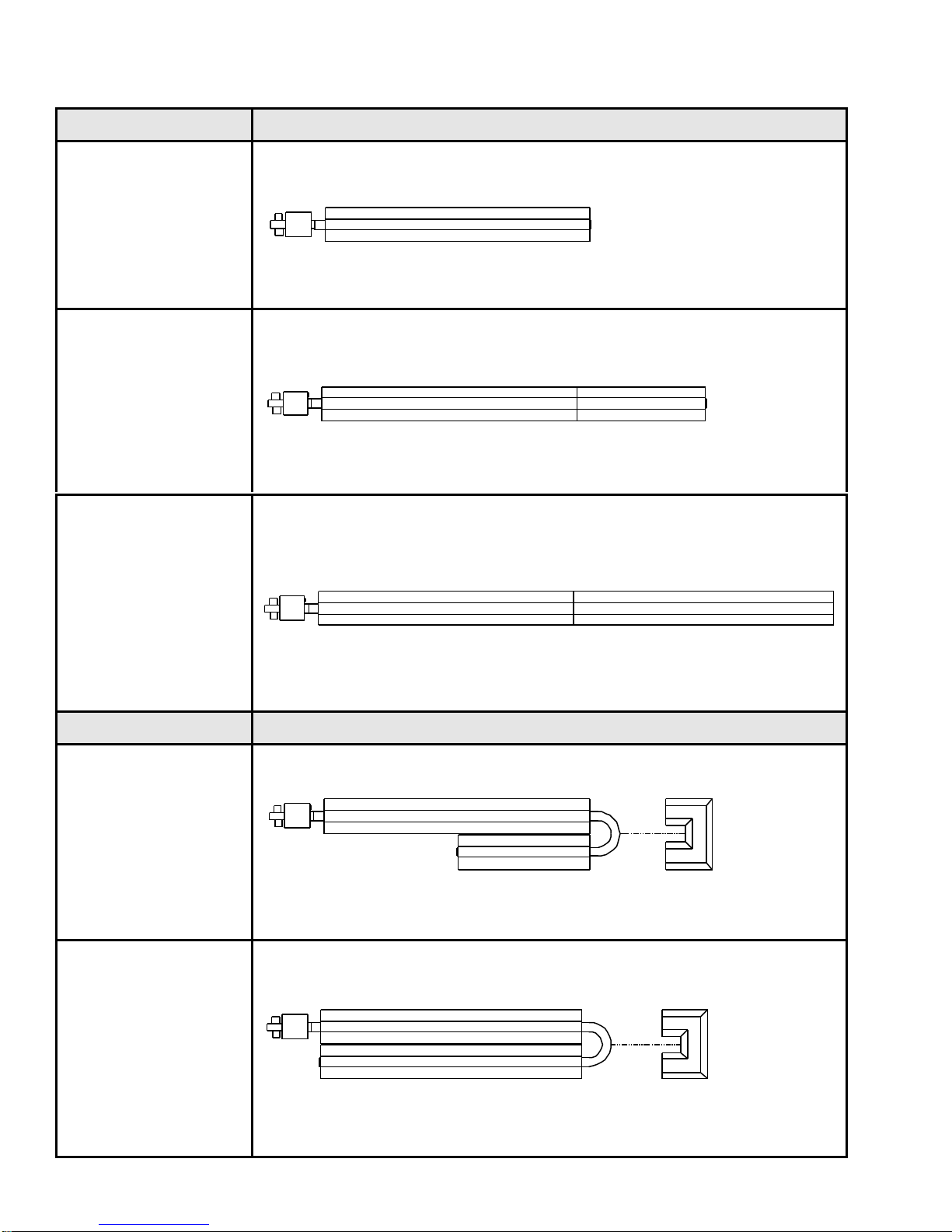
All models of low-intensity heaters include a
turbulator, which must be located in the last
ten (10) feet (3.0 m) of the burner tube
[exception: 15-foot (4.6 m) units have the
turbulator in the first10 feet (3.0 m).]
Before servicing the burner or removing the
cover panel, all electrical and gas supplies
must be disconnected.
Give consideration to construction such as
partitions, storage racks, hoists, etc., and their
relation to the installation of the heater.
The heater must be installed and serviced
ONLY by trained gas installation and service
personnel.
IMPORTANT
Failure to follow these instructions may result in injury or property damage.
RH Residential Heaters shall not be used in the following environments:
•Indoor living/sleeping quarters
•Enclosed swimming pools
•Outdoors
•Explosion-proof environments
•Process heating
•Contaminated atmosphere applications.
NOTE: Contact factory if in any doubt.