Super Handy GUT154 User manual

WARNING:
Read carefully and understand all INSTRUCTIONS before operating. Failure to follow the
safety rules and other basic safe ty precautions may result in serious personal injury.
Save these instructions in a safe place and on hand so that they can be read when
required. Keep these instructions to assist in future servicing.
Electric Height-Adjustable Standing Desk
Operator’s Manual
REV 1.3

Make sure no obstacles are in the desk’s path.
Make sure the desktop is not touching any walls.
Make sure all cords are of appropriate lengths to accommodate the change in desk height.
This sit-to-stand adjustable desk is designed for indoor using.
Keep all electrical components away from any liquids.
DO NOT open any of the components, such as lifting legs, control box, controller or socket. There is a risk
of electric shock.
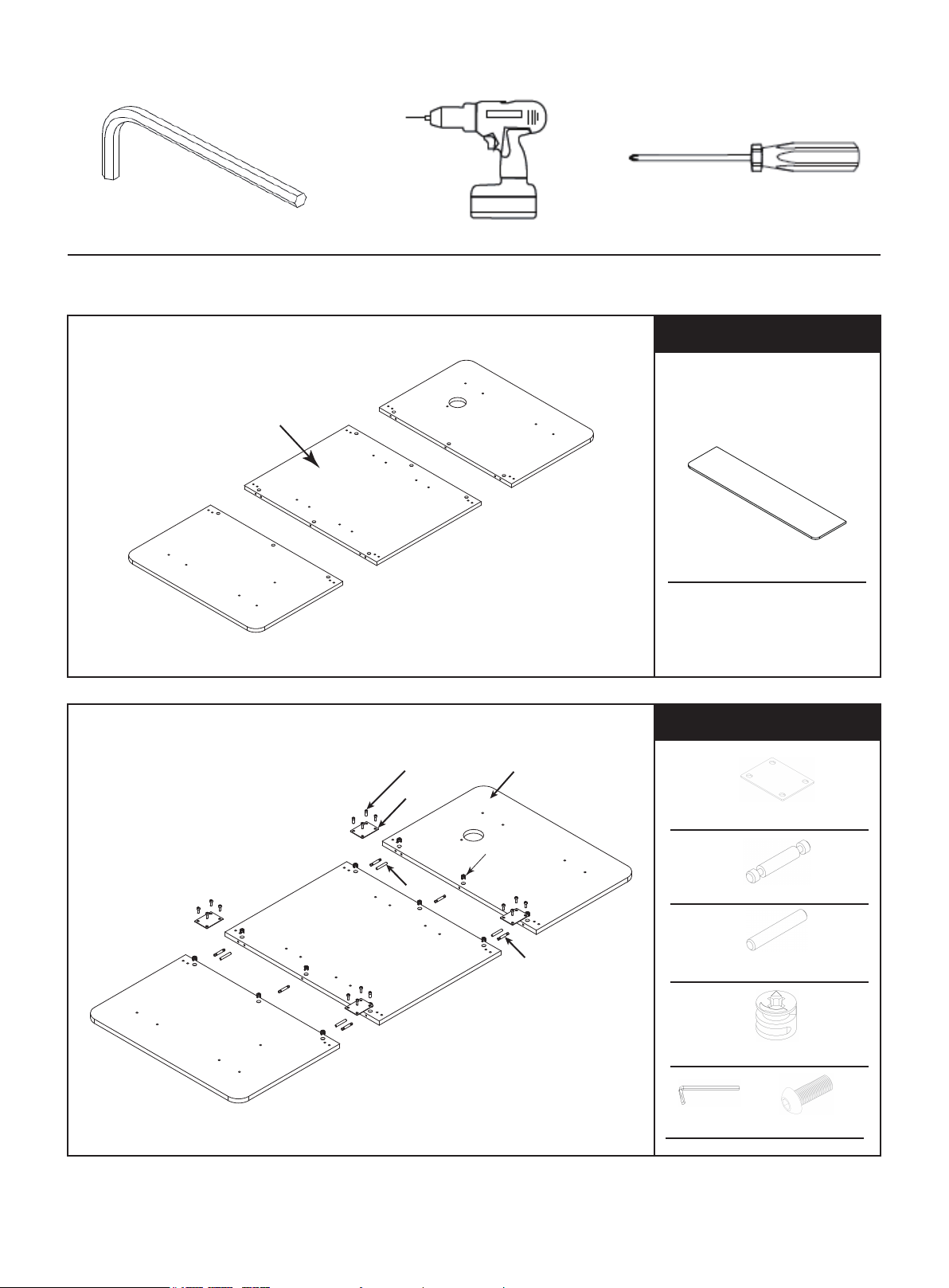
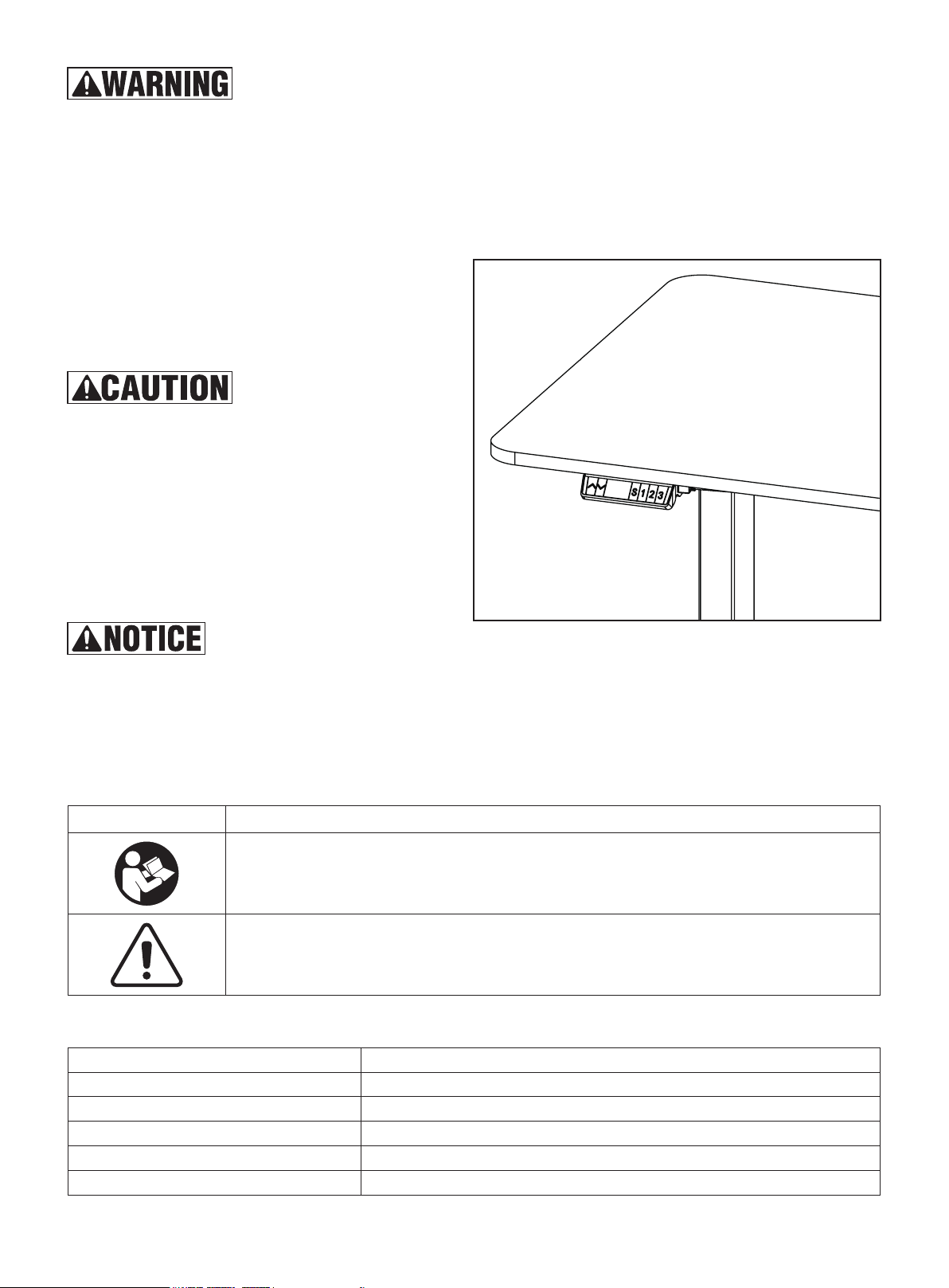
This desk must be CALIBRATED before first use.
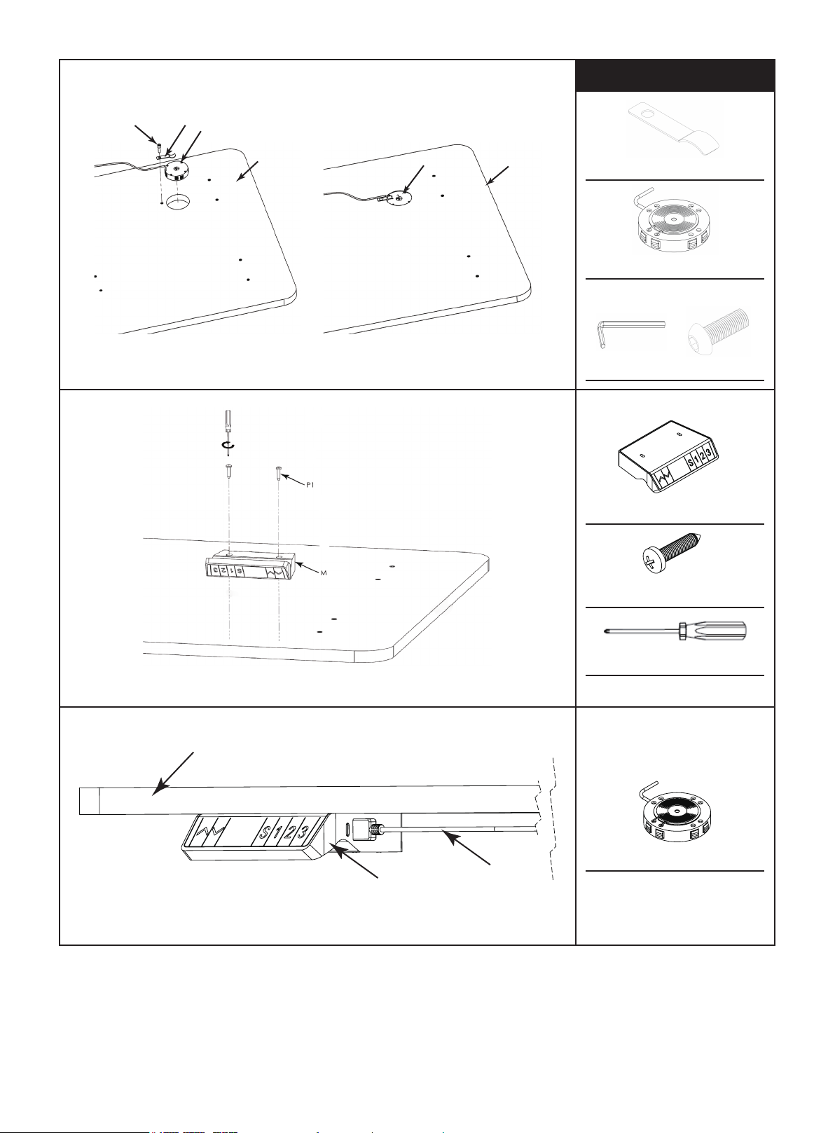
The height control module must be mounted in
place to the table in a horizontal orientation
before connecting it to the power source.
(See Fig.1)
DO NOT sit or stand on the desk.
DO NOT crawl or lie under the desk.
DO NOT place any objects taller than 20" underneath
the desk.
This product is not intended for use by young children
or for those who require supervision.
This height adjustment motors of this product is not
designed for continuous usage.
DO NOT continuously cycle the motor. For each
2 minutes of continuous cycling, allow a minimum
of 18 minutes of cool down.
The product must only be used with the provide power supply.
The manufacturer does not accept warranty claims or liability claims for any damages caused by improper usage,
assembly or handling of this standing desk product.
SAFETY SYMBOLS
Some of the following symbols are used on this product. Please study them and learn their meanings. Proper
interpretation of these symbols will help you to operate the product in a safe and responsible manner.
TECHNICAL SHEET
Fig.1
Input Voltage
Duty Cycle
The Maximum Dynamic Load
The Maximum Static Load
Cycle Time For Leg Retraction
Height Range
110V AC, 60Hz
10%, MAX. 2min. continuous motor cycling, 18min. off
100kgs / 220lbs
120kgs / 264lbs
17s
29.1"~48.4" (740~1230mm) including foot support pads
Read Operator’s Manual in its entirety.To reduce the risk of injury, user must read
and understand operator’s manual before using this product.
Safety Alert. Precautions that involve your safety.
SYMBOL MEANING
1

PARTS LIST
2
F
L
H
O
K
M
P1
E
G
QP2
S
A
B
C
R
D
V
T
IN
J

B→Foot × 2 C→Foot pad × 4
E→L Steel × 2 F→Structural part × 2
H→C Steel × 2 I→Metal pins × 6
K→Power adapter × 1 L→3-ways socket × 1
R→Wireless charger × 1
V→Plate × 1
P1→ST4.2×19 × 2
P2→ST2.9×13 × 4 Q→M6×12× 1
N→Desktop × 3
T→Locker × 12 U→Wheels × 4
A→Column × 2
G→Hook × 1
J→Wood pins × 4
M→Controller× 1
S→Connect Line× 1
O1→M6 × 12 × 16
O2→M6 × 16 × 33
O3→M6 × 35 × 8
D→Connector × 4
3

TOOLS NEEDED
ASSEMBLY
M6 Allen Key (Included) Electric Drill (Not Included) Phillips Screw Driver (Not Included)
N
4
Fig.2
Fig.3
Parts Needed
Parts Needed
D→Connector × 4
I→Metal pins × 6
J→Wood pins × 4
T→Locker × 12
M6 O2→M6 × 16 × 16
Step 1: Prepare soft material on flat surface, to protect table top. Put table top
on it. (See Fig.2)
N→Desktop × 3
Step 2: Connect two pieces table together. (See Fig.3)
N
T
I
D
O2
J

Fig.5
O1
A
E
A→Column × 2
E→L Steel × 2
M6 O1→M6 × 12 × 12
Parts Needed
Parts Needed
Fig.4
O2
O1
N
H
F
F→Structural part × 2
M6 O1→M6×12 × 4
O2→M6×16 × 8
H→C Steel × 2
Step 3: Install supporting frames. (See Fig.4)
Step 4: Install legs. (See Fig.5)
5

Parts Needed
Fig.6
Step 5: Install fixing plates at both sides. (See Fig.6)
M6 O2→M6×16 × 8
O2
Parts Needed
Step 6: Install desk foot and foot pads. (See Fig.7)
B→Foot × 2
C→Foot pad × 4
U→Wheels × 4(Alternative)
M6 O3→M6 × 35 × 8
B
C
U
O3
Alternative
Fig.7
6

N
MR
P1
M
Parts Needed
Fig.8
Fig.9
Fig.10
Step 7: Install wireless charger and controller. (See Fig.8, Fig.9, Fig.10)
N
R
V
O2
N
RV→Plate × 1
R→Wireless charger × 1
M6 O2→M6×16 × 1
M→Controller× 1
P1→ST4.2×19 × 2
Screw Driver
R→Wireless charger × 1
7

POWER
M
A
R
K
S
L
M6
G→Hook × 1
Q→M6×12× 1
Parts Needed
Fig.11
Step 8: Connect wires. (See Fig.11)
Parts Needed
Fig.12
Step 9: Install Hook. (See Fig.12)
M→Controller× 1
S→Connect Line× 1
R→Wireless charger × 1
A→Column × 2
L→3-ways socket × 1
8

OPERATION
1. Control panel
2. Calibration
The standing desk must be calibrated before first use, or when there is a system error, or if the controller displays
"RST".
Calibration operation is as follows:
a) Press and hold key “ꓦ” button on the controller until the desk reaches the lowest position and the motor stops;
b) Release the key, and then press and hold “ꓦ” again for 5 seconds to enter the initialization mode;
c) Once hear tone from buzzer, the calibration is completed;
d) DO NOT release the key “ꓦ” during calibration process. If released, the calibration process will stop, and you
should repeat above steps to complete the process.
3. Raising and Lowering your Smart Desk
a) Press and hold key “ꓥ”, desk rises until it reaches the highest position or you release the “ꓥ” key.
b) Press and hold key “ꓦ”, desk lowers until it reaches the lowest position or you release the “ꓦ” key.
4. Memory Height Setting of your Smart Desk
The controller can store three table height settings. The memory setting is as follows:
a) Position the table to your desired height. Press the "S" key, the LED display will show a flashing "S".
b) Press the key "1”, “2” or “3”, and store the current height setting of table on that key location.Once setting is
finished, press any key “1” “2” or ”3” and the table will be adjusted to the memorial height. Press any key while
the table is in motion, it will stop automatically. Settings can be changed at anytime by following the above
instructions.
5. Locking and Unlocking
Lock:
Press and hold the key "S "and "ꓥ" simultaneously for 5 seconds, LED displays “Loc”, control system is locked,
table cannot move up and down.
Unlock:
Press and hold the key "S "and "ꓦ" simultaneously for 5 seconds, LED displays table height, control system is
unlocked, and the table can move up and down as normal.
Fig.13 Fig.14
Topside (Fig.13)
ꓥ: UP Key
V: DOWN Key
S: SET Key
1: Memory height 1
2: Memory height 2
3: Memory height 3
Backside (Fig.14)
M1: Motor connector 1
DC: Power input connector
M2: Motor connector 2
9

6. Reset your Standing Desk Memory
Your Standing Desk can be reset back to the default factory setting by pressing and holding down both "ꓥ” and “ꓦ"
keys for 10 seconds. Once a long buzzer sounds, the parameters are restored back to factory default settings, and
the controller displays "RST".
Return to Calibration Step 2 above to reset your Smart Desk.
7. Height unit switching
a) Press and hold the key "S" for 5 seconds, to enter the setting interface.
b) Display "S-x" while "x" is flashing, where "x" is the selectable number. Press "ꓥ" or "ꓦ" to switch to flashing "1",
and then press "S" to enter the setting.
c) Press "ꓥ" or "ꓦ" to switch "0" or "1", 0 means centimeter unit, 1 means inch unit, select the correct parameter and
press "S" to confirm.
TROUBLE SHOOTING
Error Code
E1
E6
E7
E2
E4
E5
E8
E11, E21, E40, E41
E12,E22,E42,E43
E13, E14, E15, E16, E17
E23, E24, E25, E26, E27
E18, E28
HOT
Root Cause
Power source voltage over than 45V.
Power source voltage lower than 20V.
Working voltage lower than 20V when
moving.
Height difference of lead screw between
both sides is over 10 mm.
Connection of controller error, or lost
communication between motor and
controller.
Collision error, table touch obstacles.
Desktop sloping.
Connection cable failure.
Controller failure.
Motor failure.
Overloading/Excessive weight on desk.
Overtime or over temperature operation.
Solution
Check power source and power adaptor.
Initialization process.
Recheck connections between units,
unplug and re-plug cables.
Release key, remove obstacles under
desk.
Check the desktop, execute Initialization
process.
Check the connecting cables.
Replace the controller.
Execute Initialization process, if not
working, exchange motor.
Reduce the loading.
Automatic recovery after resting for
20 minutes.
10

Size: 210x285mm REV 05/23/23157克双铜
US CA
Great Circle USA
Support Line: 1-866-493-0524
www.greatcircleus.com
www.greatcircleca.com
Scan me to get more new products.
This manual suits for next models
3
Table of contents
Other Super Handy Indoor Furnishing manuals
Popular Indoor Furnishing manuals by other brands

Made
Made Monterosso AX8 Quick start quide

National Comfort Products
National Comfort Products Comfort Pack CPWSA Assembly instructions

aspenhome
aspenhome I224-307 Assembly instructions

Agilent Technologies
Agilent Technologies InfinityLab 5043-1711 Assembly and use instructions

Kinfine
Kinfine HOMEPOP K7643 Assembly instructions

LEMI
LEMI BELLAGIO 1M Original instructions