Superwinch S3000 User manual

OWNER’S MANUAL
INSTALLATION • OPERATION • MAINTENANCE
SAFETY PRECAUTIONS • REPAIR PARTS
S3000, S4000, S5000
12 & 24 Volt DC Electric Winches
With Remote Control
READ AND UNDERSTAND THIS MANUAL BEFORE INSTALLATION
AND OPERATION OFYOUR SUPERWINCH PRODUCT.
89-12792 Rev - 1/30/04
Superwinch, Inc. Superwinch, Ltd.
Winch Drive Abbey Rise, Whitchurch Road
Putnam, CT 06260 Tavistock, Devon PL 19 9DR
U.S.A. England
Tel. (860) 928-7787 Tel. (1822) 614101
Fax (860) 963-0811 Fax (1822) 615204
VALABLE A TRAVERS LE MONDE
GARANTIE LIMITÉE. Superwinch, Inc. (le “Vendeur”) garantit àl’acheteur d’origine (“vous”) que
toutes les pièces et composants, àl’exception du câble métallique, sont sans vice de matériaux ou
de fabrication, et ce, pendant une période d’un (1) an àcompter de la date d’achat prouvable.
Tout produit Superwinch défectueux sera réparéou remplacésans dépenses de votre part si vous
respectez ces procédures. Les garanties énoncées par les présentes sont exclusives tiennent lieu de
toutes autres garanties expresses ou implicites.
PROCÉDURE DE RECOURS ÀLA GARANTIE LIMITEE.
Dès découverte d’un produit Superwinch défectueux, vous devrez envoyer àSuperwinch, àl’usine
ou àun Centre de réparation autorisépar l’usine, une notification écrite dudit défaut et vous
devrez envoyer par courrier ou autre service de livraison le Superwinch défectueux, port et frais
postaux payés àl’avance. Les réparations ou remplacements par le Vendeur conformément àla
présente Garantie s’effectueront normalement dans les quinze (15) jours ouvrables suivant récep-
tion du Superwinch défectueux. Le Vendeur ou ses Agents autorisés peut facturer des frais
raisonnables pour les pièces et la main d’oeuvre en cas de réparation non couverte par la présente
Garantie limitée.
LIMITATIONS ET EXCLUSIONS EN CE QUI CONCERNE LA GARANTIE ET LES REMÈDES.
La réparation et/ou le remplacement de tout Superwinch défectueux ou de tout composant d’un
tel Superwinch tel que convenu par les présentes est votre remède exclusif. Les exclusions et limita-
tions de garanties et les limitations de REMEDES ci-dessous seront expressément applicables :
A. Garanties expresses . Le Vendeur garantit que le Superwinch est tel qu’il est décrit dans le
“Mode d’emploi Superwinch”fourni avec la présente; aucune autre garantie expresse n’est don-
née en ce qui concerne le Superwinch. Si un modèle ou échantillon vous a étémontRé, ledit mod-
èle ou échantillon a étéutiliséàdes fins d’illustration uniquement et ne sera pas considéréune
garantie que le Superwinch sera conforme au modèle ou àl’échantillon. LE VENDEUR NE DONNE
AUCUNE GARANTIE EXPRESSE EN CE QUI CONCERNE LE CABLE MÉTALLIQUE INCORPORÉAU PRO-
DUIT.
B. Garantie implicite . LA GARANTIE IMPLICITE DE L’APTITUDE ÀLA VENTE ET TOUTE AUTRE
GARANTIE IMPLICITE S’APPLIQUERA UNIQUEMENT POUR UNE DURÉE D’UN (1) AN ÀCOMPTER DE
LA DATE D’ACHAT PROUVABLE. LE CABLE MÉTALLIQUE EST VENDU “TEL QUEL”SANS AUTRE
GARANTIE IMPLICITE. CERTAINS ÉTATS AMÉRICAINS NE PERMETTENT PAS DE LIMITER LA DURÉE
DES GARANTIES IMPLICITES; IL EST DONC POSSIBLE QUE LA LIMITATION CI-DESSUS NE S’APPLIQUE
PAS ÀVOTRE CAS.
C. Dommages indirects. SUJET AUX OBLIGATIONS DE LA GARANTIE LIMITÉE DU VENDEUR
ÉNONCÉES DANS LE PRÉSENT DOCUMENT, LE VENDEUR NE SERA AUCUNEMENT RESPONSABLE DE
DOMMAGES INDIRECTS, DE QUELQUE NATURE QUE CE SOIT, NI DE DOMMAGES INDIRECTS ÀLA
PROPRIÉTÉ, NI DE PERTES DE PROFITS, NI DE PERTES D’UTILISATION POUVANT SURVENIR ÀCAUSE
D’UN DÉFAUT, D’UN MAUVAIS FONCTIONNEMENT OU D’UNE PANNE QUELCONQUE DU SUPER-
WINCH CI-JOINT. CERTAINS ÉTATS AMÉRICAINS NE PERMETTENT PAS D’EXCLURE OU DE LIMITER
LES DOMMAGES INDIRECTS; IL EST DONC POSSIBLE QUE LA LIMITATION CI-DESSUS NE S’APPLIQUE
PAS ÀVOTRE CAS.
D. Condition de la garantie. Le Vendeur ne sera pas tenu de se conformer aux obligations de
garantie fournies par les présentes si la cause du défaut, du mauvais fonctionnement ou de la
panne du Superwinch est un dommage (ne résultant pas de composants défectueux ou qui fonc-
tionnent mal) ou une utilisation déraisonnable par vous. Le terme Utilisation déraisonnable com-
prend mais ne est pas limitéau manquement àla maintenance, àl’installation et àl’utilisation
raisonnables et nécessaires conformément aux consignes contenues dans le Mode d’emploi
Superwinch, et àl’utilisation du Superwinch pour des charges supérieures àcelle figurant dans le
Mode d’emploi pour le modèle en question. La responsabilitédu Vendeur sous la présente
garantie ou pour toute perte du produit Superwinch ou dommage àcelui-ci ne dépassera pas le
coût de correction des défauts du produit Superwinch ou de remplacement de celui-ci, et lors de
l’expiration de la période de garantie, toute telle responsabilitéprendra fin. Les agents, distribu-
teurs et employés du Vendeur ne sont pas autorisés àmodifier la présente garantie ni àdonner
d’autres garanties complémentaires obligatoires pour le Vendeur. Toute déclaration supplémen-
taire, qu’elle soit écrite ou orale, ne constituera donc pas une garantie et ne devra pas être consid-
érée comme valable.
REMEDES LÉGAUX DE L’ACHETEUR. Cette garantie limitée vous donne des droits légaux spéci-
fiques et il est possible que vous ayez d’autres droits qui varient d’un état àl’autre aux Etats-Unis
et d’un pays àl’autre. Vous avez également des droits de garantie implicite. En cas de problème
avec le service ou la performance suivant la garantie limitée, il est possible que vous puissiez inten-
ter une action en justice devant la Cour des Prudhommes (“small claims court”), devant le tribunal
d’état ou devant le tribunal fédéral des Etats-Unis ou dans une autre juridiction appropriée en
dehors des Etats-Unis.
QUESTIONS. Toute question en ce qui concerne le respect des garanties énoncées dans les
présentes doit être envoyée, par écrit, à: Superwinch, Inc., Winch Drive, Putnam, CT 08260 U.S.A.
ou àSuperwinch Limited, Abbey Rise, Whitchurch Road, Tavistock, Devon PL 19 9DR, England
GARANTIE LIMITÉE

Ratings assume a 10% coefficient of friction.
* A 10% slope is a rise of one foot in ten feet.Slope in approximate degrees is also shown above.
** All loads shown are for single-line operation. Double-line operation with optional pulley block
(see Figure 2) approximately doubles capacity of winch.
Figure 1
Freespool Clutch
In-Drum Brake
Remote Switch
Receptacle
Permanent
Magnet Motor
GENERAL DESCRIPTION
Integrated Solenoids
32
Thank you for purchasing an S series winch from Superwinch. It has been designed and
manufactured to provide years of trouble-free operation. We hope you will be pleased
with its performance. If you are not, for any reason, please contact our Customer Service
Department: (860) 928-7787 USA; (1822) 614101 England.
When requesting information or ordering replacement parts; always give the
following information:
1. Winch Part Number
2. Serial Number (found on housing)
3. Part Number (found in Replacement Parts List section)
4. Part Description
Please read and understand this Owner’s Manual before installing your winch. Pay particular
attention to the General Safety Information. Your winch is a very powerful machine. If used
unsafely or improperly, there is a possibility that property damage or personal injury could
result. We have included several features in the winch to minimize this possibility; however,
your safety ultimately depends on your caution when using this product.
Throughout this manual, you will find notations with the following headings:
Indicates an imminently hazardous situation which, if not avoided,
will result in death or serious injury.
Indicates a potentially hazardous situation which, if not avoided,
could result in death or serious injury.
Indicates a potentially hazardous situation which, if not avoided, may
result in minor or moderate injury. This notation is also used to alert
against unsafe practices.
Note: Indicates additional information in the installation and operation procedures
of your winch.
Correct installation of your winch is a requirement for proper operation.
Please Note: The Superwinch S series winch is designed primarily for intermittent duty
general use. This winch is not designed to be used in industrial or hoisting applications
and Superwinch does not warrant it to be suitable for such use. Superwinch manufactures
a separate line of winches for industrial/commercial use. Please contact our Customer Service
Department for further information.
Congratulations on your choice!
INTRODUCTION
CAUTION
!
Roller Fairlead
Slope* 10% (6º) 20% (11º) 30% (17º) 100% (45º)
Lbs.**
kg**
12,563
5,698
8,503
3,857
6,527
2,961
3,213
1,457
ROLLING LOAD CAPACITIES
S3000
Working Load* . . . . . . . . . . . . . . . . . . . . . . . . . . . . . . . . . . . . . . . . . 3,000 lb. (1361 kg)
Wire Rope . . . . . . . . . . . . . . . . . . . . . . . . . . . . . . . . . . . . . . . . . . . . 3/16" x 60'
Motor . . . . . . . . . . . . . . . . . . . . . . . . . . 12V or 24VDC 1.3 hp (0.97 kW) peak
Gear Ratio . . . . . . . . . . . . . . . . . . . . . . . . . . . . . . . . . . . . . . . . . . . . . . . . 159:1
S4000
Working Load* . . . . . . . . . . . . . . . . . . . . . . . . . . . . . . . . . . . . . . . . . 4,000 lb. (1814 kg)
Wire Rope . . . . . . . . . . . . . . . . . . . . . . . . . . . . . . . . . . . . . . . . . . . . 7/32" x 60'
Motor . . . . . . . . . . . . . . . . . . . . . . . . . . 12V or 24VDC 1.8 hp (1.34 kW) peak
Gear Ratio . . . . . . . . . . . . . . . . . . . . . . . . . . . . . . . . . . . . . . . . . . . . . . . . 159:1
S5000
Working Load* . . . . . . . . . . . . . . . . . . . . . . . . . . . . . . . . . . . . . . . . . 5,000 lb. (2268 kg)
Wire Rope . . . . . . . . . . . . . . . . . . . . . . . . . . . . . . . . . . . . . . . . . . . . 1/4" x 50'
Motor . . . . . . . . . . . . . . . . . . . . . . . . . . 12V or 24VDC 2.1 hp (1.57 kW) peak
Gear Ratio . . . . . . . . . . . . . . . . . . . . . . . . . . . . . . . . . . . . . . . . . . . . . . . . 159:1
* Based on first layer performance
SPECIFICATIONS
S5000
S4000
S3000
Slope* 10% (6º) 20% (11º) 30% (17º) 100% (45º)
Lbs.**
kg**
17,588
7,978
11,905
5,400
9,138
4,145
4,499
2,041
Slope* 10% (6º) 20% (11º) 30% (17º) 100% (45º)
Lbs.**
kg**
22,613
10,257
15,306
6,943
11,749
5,329
5,784
2,624

Description Quantity
Winch assembly with wire rope including lead wires 1
Circuit breaker assembly with hardware 1
Handsaver 1
Mounting hardware kit 1
Remote pendant 1
Owner’s manual 1
This carton contains the following items. Please unpack carefully.
Read instructions before beginning.
UNPACKING
DIMENSIONS
S3000, S4000, S5000
Figure 2
PERFORMANCE
Wire Rope Max. Pulling Capacity
Layer lbs. kg
1 3,000 1364
2 2,250 1021
3 2,000 907
4 1,750 794
Motor
Load Speed Current
lbs. kg ft/min m/min Amps
0 0 17.0 5.1 15
1,000 454 12.5 3.8 70
2,000 907 9.0 2.7 117
2,500 1134 7.5 2.3 155
3,000 1361 4.5 1.4 220
S3000
Wire Rope Max. Pulling Capacity
Layer lbs. kg
1 4,000 1818
2 3,000 1361
3 2,600 1179
4 2,000 998
Motor
Load Speed Current
lbs. kg ft/min m/min Amps
0 0 21.6 6.5 30
1,000 454 16.0 4.8 90
2,000 907 12.4 3.8 155
2,500 1134 10.6 3.2 180
3,000 1361 8.8 2.7 215
3,500 1589 6.2 1.9 250
4,000 1814 4.5 1.4 311
Wire Rope Max. Pulling Capacity
Layer lbs. kg
1 5,000 2273
2 4,000 1814
3 3,500 1588
4 2,900 1315
Motor
Load Speed Current
lbs. kg ft/min m/min Amps
0 0 17.5 5.9 36
1,000 454 14.5 4.6 80
2,000 907 12.0 3.4 135
3,000 1361 9.5 2.2 200
4,000 1814 7.3 1.3 265
5,000 2268 4.5 1.4 350
S4000
S5000
* Based on first layer performance
NOTES
1. All dimensions are in inches [millimeters].
2. Typical mount is to flat surface capable of handling the loads. Bolts to be Grade 5 or better.
6.0
(152)
15.1
(383)
7.2
(183)
7.1
(180)
3.1
(79)
5.9
(150)
3.69
(93.7)
1.24
(31.5)
ROLLER FAIRLEAD
SCREWS
DRUM SUPPORT
PLATE SCREWS
MOTOR
SCREWS
4 5
DRUM SUPPORT
PLATE

Your S series winch is a very powerful
machine. Treat it with respect, use it
with caution and always follow the
safety guidelines.
The wire rope
may break
before the winch stalls. For heavy
loads, use a pulley block to reduce
the load on the wire rope.
1. The S3000, S4000, and S5000
winch is rated at 3,000, 4,000,
and 5,000 pounds (1361, 1814,
2268 kg) (single line) capacity on
the wire rope layer closest to the
drum. DO NOT OVERLOAD. DO
NOT ATTEMPT PROLONGED
PULLS AT HEAVY LOADS. Do not
maintain power to the winch if
the motor stalls. Overloads can
damage the winch and/or the
wire rope and create unsafe
operating conditions. FOR LOADS
OVER 2/3RATED CAPACITY, WE
RECOMMEND THE USE OF THE
OPTIONAL PULLEY BLOCK TO
DOUBLE LINE THE WIRE ROPE
(Figures 3 & 18). This reduces the
load on the winch and the strain
on the wire rope by approximately
50%. If attaching back to vehicle,
attach to the frame or other load
bearing part. The vehicle engine
should be running during winch
operation to minimize battery drain
and maximize winch power and
speed. If considerable winching is
performed with the engine off,
the battery may be too weak to
restart the engine.
2. AFTER READING AND UNDER-
STANDING THIS MANUAL,
LEARN TO USE YOUR
WINCH. After
installing the winch, practice
using it so you will be familiar
with it when the need arises.
3. DO NOT “move”your vehicle to
assist the winch in pulling the
load. The combination of the
winch and vehicle pulling together
could overload the wire rope and
the winch.
4. KEEP WINCHING AREA CLEAR. Do
not allow people to remain in the
area during winching operations.
ALWAYS STAND CLEAR OF WIRE
ROPE, HOOK AND WINCH. IN THE
UNLIKELY EVENT OF ANY COM-
PONENT FAILURE, IT IS BEST TO
BE OUT OF HARM‘S WAY.
5. INSPECT WIRE ROPE AND EQUIP-
MENT FREQUENTLY. A FRAYED
WIRE ROPE WITH BROKEN
STRANDS SHOULD BE REPLACED
IMMEDIATELY. Always replace
wire rope with the manufacturer‘s
identical replacement part (see
Replacement Parts List).
Periodically check the winch
installation to ensure that all
bolts are tight.
6. USE HEAVY LEATHER GLOVES
when handling wire rope. DO
NOT LET WIRE ROPE SLIDE
THROUGH YOUR HANDS EVEN
WHEN WEARING GLOVES.
7
GENERAL SAFETY
INFORMATION
Figure 3
Single Line
Double Line
INTERMITTENT DUTY
An electric winch is like any other
motor driven power tool such as
an electric drill or saw. The electric
motor should not be allowed to
become excessively hot. Normal
precautions will extend the life
of your motor. Keep the duration
of pulls as short as possible. If
the end of the motor becomes
uncomfortably hot to touch,
stop winching and allow the
motor to cool down.
If the winch
motor stalls,
do not continue to apply power
to the winch.
6
FEATURES
Electric Motor –1.3 (S3000),
1.8 (S4000), 2.1 (S5000) peak hp
(.97 (S3000), 1.34 (S4000), 1.57
(S5000) kW) 12V or 24Volt
Permanent Magnet.
Braking –A wrap spring brake
which will hold 50% of rated load
on the first wrap. Reducing by
approximately 10% per layer
thereafter.
Drum –Die cast aluminum running
in maintenance free bearings.
Freespool Clutch –Operated by
an easy action lever which disen-
gages the gearbox to allow the
wire rope to be pulled out without
using electric power. A tension
plate reduces backlash and snarling
when pulling out the wire rope.
Remote Switch –30' (13.64 m)
hand held pendant switch assembly
with toggle switch.
Mounting –Optional custom
engineered mounting kits are available
for vehicle frame attachment.
European Union
Noise The noise level of this winch in operation is below 92 dB(A).
Emergency Stop In order to conform to Machinery Directive 89/392/EEC, each machine installation must be
fitted with an Isolator (Part Number 8370) whereby the machine can be brought safely to a complete stop.

7. NEVER WINCH WITH LESS THAN
5 TURNS of wire rope AROUND
THE WINCH DRUM since the
wire rope end fastener will NOT
withstand a load. ALWAYS USE
THE HANDSAVER when guiding
the wire rope in or
out (see Figure 4).
8. KEEP CLEAR OF
WINCH, TAUT WIRE ROPE AND
HOOK WHEN OPERATING
WINCH. Never put your finger
through the hook. If your finger
should become trapped in the
hook, you could lose your finger.
Never guide a wire
rope onto the drum
with your hand.
9. NEVER HOOK THE WIRE ROPE
BACK ONTO ITSELF because you
could damage the wire rope.
Use a nylon sling (Figure 5).
10. It is a good idea to lay a heavy
blanket or jacket over the wire
rope near the hook end when
pulling heavy loads (Figure 6). If
a wire rope failure should occur,
the cloth will act as a damper
and help prevent the rope from
whipping. Raise the hood of the
vehicle for added protection.
11. NEVER USE YOUR
WINCH FOR LIFTING
OR MOVING PEOPLE.
12. Your winch is not designed or
intended for overhead hoisting
operations.
13. AVOID CONTINUOUS PULLS
FROM EXTREME ANGLES as this
will cause the wire rope to pile
up at one end of the drum
(Figure 7). This can jam the wire
rope in the winch, causing damage
to the rope or the winch.
14. NEVER OBSCURE THE WARNING
INSTRUCTION LABELS.
15. Always operate winch with an
unobstructed view of the winch-
ing operation.
16. Equipment such as tackle, hooks,
pulley blocks, straps, etc. should
be sized to the winching task
and should be periodically
inspected for damage that could
reduce their strength.
17. NEVER RELEASE FREESPOOL
CLUTCH WHEN THERE IS A LOAD
ON THE WINCH.
18. STORE THE REMOTE PENDANT
ASSEMBLY IN A SAFE PLACE
when not in use to prevent use
by children or other unautho-
rized persons.
19. DO NOT OPERATE WINCH
WHEN UNDER THE INFLUENCE
OF DRUGS, ALCOHOL OR
MEDICATION.
20. ALWAYS UNPLUG THE REMOTE
PENDANT BEFORE WORKING IN
OR AROUND THE FAIRLEAD OR
WINCH DRUM (THE DANGER
ZONE) so that the winch cannot
be turned on accidentally.
21. When moving a load, slowly
take up the wire rope slack until
it becomes taut. Stop, recheck
all winching connections. Be
sure the hook is properly seated.
If a nylon sling is used, check the
attachment to the load.
22. When using your winch to move
a load, place the vehicle transmis-
sion in neutral, set vehicle park-
ing brake and chock all wheels.
23. DO NOT USE THE WINCH TO
HOLD LOADS IN PLACE.
Use other means of securing
loads such as tie down straps.
Superwinch offers a wide
variety of tie downs.
Contact your local
Superwinch dealer.
24. USE ONLY FACTORY APPROVED
SWITCHES, REMOTE CONTROLS
AND ACCESSORIES. Use of non-
factory approved components
may cause injury or property
damage and could void your
warranty.
25. DO NOT MACHINE OR WELD
ANY PART OF THE WINCH. Such
alterations may weaken the
structural integrity of the winch
and could void your warranty.
26. Do not power the winch out for
more than 50 feet (15.2m) or
longer than 2 minutes.
The drum
and wire rope
may get very hot (Figure 8).
27. DO NOT CONNECT WINCH TO
EITHER 110V AC HOUSE CUR-
RENT OR 220V MAINS AS WINCH
BURNOUT OR FATAL SHOCK
MAY OCCUR!
28. Never allow shock loads to be
applied to winch or wire rope.
29. Use caution when pulling or
lowering a load up and down a
ramp or incline. Keep people,
pets and property clear of the
path of the load.
GENERAL SAFETY
INFORMATION
(CONT.)
Figure 8
9
8
GENERAL SAFETY
INFORMATION
(CONT.)
Wrong Right
Right Wrong
Figure 7
Figure 5
Figure 6
Figure 4
HOT!

Do not sub-
stitute any
strength grade weaker than
grade 5.
When attaching wires to the motor
terminals and solenoid (relay), hold
the inner nut when tightening the
outer nut. Do not allow the motor
terminals to rotate for it may cause
internal wire breakage or part mis-
alignment. Be especially careful in
preventing the solenoid (relay)
terminals from rotating. Any
rotation can damage the solenoid
(see Figure 10).
Step (3)
Disconnect the vehicle battery
leads.
Automobile
batteries con-
tain gasses which are flammable
and explosive. Wear eye protection
during installation and remove all
metal jewelry. Do not lean over bat-
tery while making connections.
Step (4)
Route the two (2) wires through
the vehicle grille to the battery. To
ensure against insulation abrasion
and/or cutting, apply several layers
of electrical tape where wiring may
come in contact with sharp metal
parts of the vehicle. Attach the cir-
cuit breaker assembly to the end of
the blue terminated wire. Wrap the
circuit breaker assembly with elec-
trical tape to prevent accidental
short circuits.
INSTALLATION
CONT.
11
Be Prepared
Figure 11
Figure 10
Superwinch mounting (fitting) kits
are available for most popular vehi-
cles. If you can‘t locate a kit locally
contact Superwinch at the address
listed on the front of this manual
for the name of a Superwinch dealer
near you.
Detailed Mounting instructions are
provided with each mounting kit.
Read and follow directions carefully
to ensure proper winch alignment
and trouble free operation.
This winch
MUST be mount-
ed with the wire rope in the under-
wind direction. Improper mounting
could damage your winch and void
your warranty.
MINIMUM ELECTRICAL
REQUIREMENTS
For 12 volt winches, a 60 ampere
alternator and battery with 440
cold-cranking amperes capacity are
the minimum recommended power
sources. If the winch is in heavy use,
an auxiliary battery and heavy duty
alternator are recommended.
Step (1)
Install mounting kit or structural
support for winch.
Step (2)
Mount the winch to the mount that
you have designed.
Mounting bolts supplied are the
correct length for use with up to a
1/4" (6.3mm) thick plate.
INSTALLATION
MOUNTING
YOUR WINCH
NOTES
1. All dimensions are in inches [millimeters].
2. Typical mount is to flat surface capable of handling the loads. Bolts to be Grade 5 or better.
6.0
(152)
15.1
(383)
7.2
(183)
7.1
(180)
3.1
(79)
5.9
(150)
3.69
(93.7)
1.24
(31.5)
10
ROLLER FAIRLEAD
SCREWS
DRUM SUPPORT
PLATE SCREWS
MOTOR
SCREWS
DRUM SUPPORT
PLATE
Figure 9

PULLING OUT THE WIRE ROPE
The wire rope has been installed on
your winch under minimal load at
the factory. The wire rope must be
respooled onto the drum under
load so that the outer layers will
not draw down into the inner ones,
thereby damaging the wire rope.
Lift the clutch lever to the “Free”
position as shown in Figure 13. If
there is a load on the wire rope,
the clutch lever may not turn easily.
DO NOT FORCE THE CLUTCH LEVER.
Release tension on the wire rope
by jogging out some of the wire
rope. Releasing the clutch and pull
out the wire rope and secure to
anchor or load. Check that there
are at least five (5) turns of wire
rope left on the drum. Re-engage
the drum by returning the clutch
lever to the “Engaged”position
(see Figure 14).
Lever must
be in the
“Engaged” position and locked
before winching.
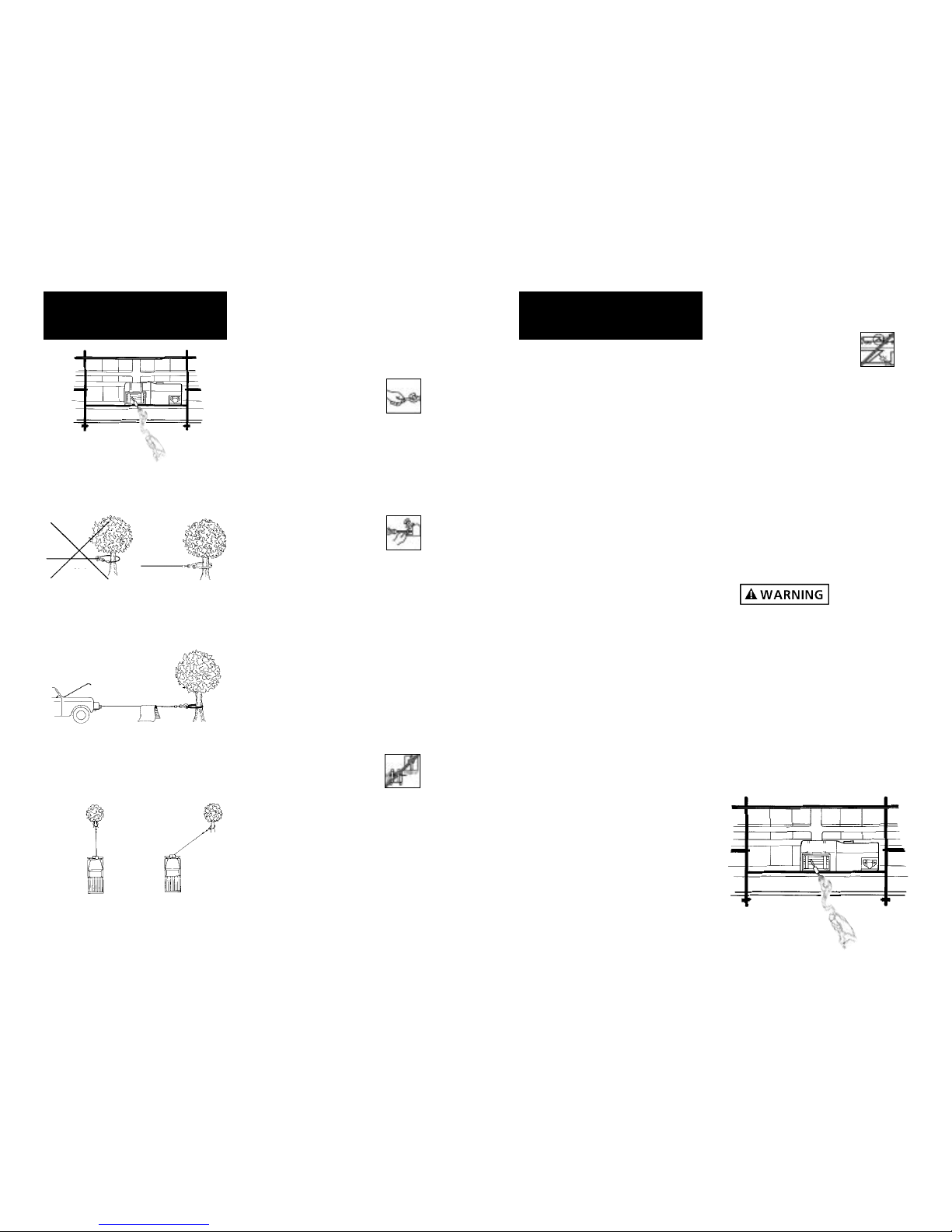
TIPS FOR EXTENDING THE LIFE OF
YOUR WINCH
1. KEEP THE WIRE ROPE TIGHTLY
WOUND ON THE DRUM. Do not
allow the wire rope to become
loosely wound. A loosely-wound
spool allows a wire rope under
load to work its way down into
the layers of wire rope on the
drum. When this happens, the
wire rope may become wedged
within the body of the windings
damaging the wire rope. To pre-
vent this problem, keep the wire
rope tightly and evenly wound
on the drum at all times. A good
practice is to rewind the wire
rope under tension after each
use. One way to do this is to
attach the hook to a stationary
object at the top of a gradual
incline and winch your vehicle
up the incline.
2. DO NOT ALLOW WINCH MOTOR
TO OVERHEAT. Remember, the
winch is for intermittent use only.
During long or heavy pulls the
motor will get hot. For pulling
at rated capacity, allow motor
to cool after 20 seconds of “On”
time. At loads less than 50%of
rated capacity, allow to cool after
2 minutes of “On”time. KEEP THE
ENGINE RUNNING TO RECHARGE
THE BATTERY during this break.
3. USE A PULLEY BLOCK FOR HEAVY
LOADS. To maximize winch and
wire rope life, use a pulley block
to double line heavier loads
(Figure 15).
13
Figure 14
FREE
ENGAGED
Figure 15
Note: If you choose to locate the
winch at a greater distance than
the wires provided will permit,
it may be necessary to purchase
a larger gauge wire to get the
best performance from your winch.
If the total length of additional
wire to be added to the system
exceeds 10' (3m), use a larger wire
gauge size.
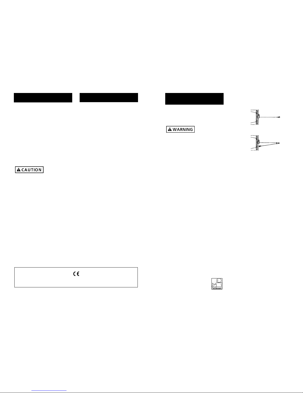
Attach the circuit breaker directly
to the battery positive terminal,
and reattach the terminal to the
battery. If your vehicle is equipped
with side pole terminals, it may
be necessary to obtain auxiliary
side terminal bolts from your
localauto parts dealer to make
these connections.
Connect the remaining wire to the
battery negative terminal, and con-
nect the terminal to the battery.
Step (5)
Lift the freespool clutch lever to
the “Free”position. Pull several
feet of wire rope off the drum.
Return the clutch lever back to
the “Engaged”position. Plug in
the remote pendant control.
Switch the slide lever to the
“Rope Out”position. Pull the
trigger momentarily to check wire
rope drum rotation and direction.
If the drum rotates in the wrong
direction, recheck your wiring.
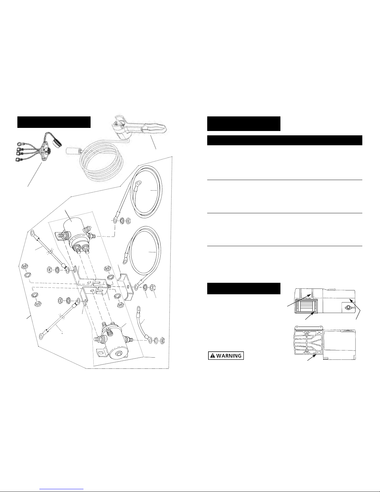
The Hand-held pendant switch
activates a solenoid that activates
power to the winch motor. One
solenoid is for “Rope Out”motor
direction and the other is for the
“Rope In”motor direction (Fig. 12).
To prevent
unauthorized
use of the winch, remove pendant
control and store in a clean dry area
such as the glove box.
PENDANT OPERATION
The handheld pendant switch
activates a solenoid that activates
power to the winch motor. To con-
nect the pendant control, remove
the cover on the plug receptacle
(Figure 13) and insert the plug
end of remote switch. The plug
on the pendant control cord is
keyed and will fit into the socket
only one way. The switch trigger
returns to the “Off”position when
released. To change direction,
move the toggle in the other
direction. (Fig.12)
The switch
assembly must
be kept free of dirt and moisture
to ensure safe operation.
12
INSTALLATION
CONT.
Figure 12
Cable In
Cable Out
AB
DUST
COVER
Figure 13

HOT!
BRAKE OPERATION
Your S Series winch has a wrap
spring brake that stops and holds
loads up to 50%rated capacity on
the first layer of wire rope closest
to drum.
Each additional layer of wire rope
reduces brake capacity approxi-
mately 10%. When powering the
winch in, the brake is disengaged
and does not become activated
until the motor is turned off and
the load tries to pull the wire rope
off the drum. When the winch is
powered out, as in releasing a load,
the brake is engaged and the motor
must over power the brake drag to
rotate the drum. Therefore, it is
normal for the winch to operate
faster in one direction than the
other. The brake is designed for the
wire rope to be used in the under-
wind position only. DO NOT OVER-
WIND. Powering against the brake
will cause heat to build up in the
drum and may transfer heat to the
wire rope (Figure 19). DO NOT
POWER OUT FOR MORE THAN 50
FEET (15.2m) OR 2 MINUTES.
The drum and
wire rope may
get very hot.
When wire rope is removed from
the drum, as in bringing the hook
to the load, the freewheel feature
of the winch should be used.
15
Figure 19
4. The pull required to start a load
moving is often much greater
than the pull required to keep
it moving. AVOID FREQUENT
STOPS AND STARTS during pull.
5. PREVENT KINKS BEFORE THEY
OCCUR.
a. This is the start of a kink. At
this time, the wire rope should
be straightened.
b. The wire rope was pulled and
the loop has tightened to a
kink. The wire rope is now per-
manently damaged and must
be replaced.
c. Kinking causes the wire strands
under the greatest tension to
break and thus reduces the
load capacity of the wire rope.
The wire rope must be replaced.
6. EQUIPPING THE WINCH WITH A
ROLLER FAIRLEAD will substantially
reduce wear on the wire rope
during angle pulls (Figure 17).
The rollers eliminate heavy rub-
bing and abrasion to the wire rope.
Periodically check tightness of
mounting bolts and electrical con-
nections. Remove any dirt or corro-
sion that may have accumulated
on the electrical connections.
Repair should be done by
Authorized Superwinch Repair
Centers ONLY. Do not attempt
to disassemble the gearbox.
Disassembly will void warranty.
LUBRICATION
The gearbox and drum bearing are
permanently lubricated with a high
performance gear lube. If relubrica-
tion is necessary (after repair or
disassembly) only use Shell Alvenia
EP2 or equivalent.
REPLACING THE WIRE ROPE
Never substitute a heavier or lighter
wire rope. Never use rope made of
any material other than wire.
Always replace damaged wire
rope with manufacturer’s identi-
cal replacement part (see
Replacement Parts list). Pass attach-
ing end of wire rope through the
fairlead (if equipped) and attach it
to the drum. When inserting the
wire rope into the drum, insert it
into the correct end of the hole
provided (Figure 18). Tighten the
set screw securely.
It is important that the wire rope be
wound tightly onto the drum. A
good way to do this is to attach the
wire rope hook to a fixed object at
the top of a slight incline, then
winch the vehicle up the incline.
14
MAINTENANCE
AND REPAIRS
Figure 16
a
b
c
Figure 17
Figure 18

1 Base 89-52021 1
2 Groove Pin 89-23303-01 2
3 Cable Guard 89-32268 1
4 Main Bearing 89-22268 1
5 M6 x 1 x 8mm Cup Pt. Set Screw 90-23164-12 1
7 Drum Bearing 89-22269 1
8 Drum Support 89-40092 1
9 Thrust Washer 90-12574 2
10 Drive Plate 89-32263 1
11 Rotating Ring Gear 89-32265 1
12 Planetary Carrier Assembly 89-22141 1
14 Sun Gear 89-33303 1
15 Stationary Ring Gear 89-32266 1
16 Free Wheel Repair Kit 89-10580 1
(Includes Shaft, Lever, Handle, and Rivet)
17 Free Wheel Spring 90-23152-08 1
18 M6 x 1 x 16mm Flat Head Screw 89-22291-01 4
20 Housing Assembly (includes 21 & 22) 89-40104 1
21 Needle Bearing (.8125 x 1.125 x .750) 89-23263-03 1
22 Motor Shaft Bearing 89-12002 1
23 S5000 Logo 89-17332 1
S4000 Logo 89-17331 1
S3000 Logo 89-17330 1
27 M6 x 1 x 13mm Button Head Screw 89-22290-01 2
29 Cable Tension Spring 89-32295 1
30 Handsaver 87-31120 1
31 Wire Rope Assembly w/hook 1/4"x50' (S5000) 1577A 1
Wire Rope Assembly w/hook 7/32"x60' (S4000) 1514A 1
Wire Rope Assembly w/hook 3/16"x60' (S3000) 1511C 1
32 M6 x 1 x 16mm Button Head Screw 89-22290-02 5
33 12 Volt Complete Motor (S5000) 90-33294 1
24 Volt Complete Motor 89-33298 1
12 Volt Complete Motor (S4000) 90-32295 1
24 Volt Complete Motor 89-33297 1
12 Volt Complete Motor (S3000) 90-33276 1
24 Volt Complete Motor 89-33296 1
37 Motor Cover 89-52024 1
38 “Superwinch”Nameplate 89-22277 1
39 M4 x 0.7 x 6mm Hex Washer Head Screw 89-22292-01 4
42 Drum 89-40085 1
43 Brake Spring 89-22342 1
44 Brake Adapter 89-22287 1
45 Roller Fairlead 89-40123 1
46 Roller Fairlead Frame 89-40113 1
47 Roller Fairlead Shaft (Long) 89-22334-02 2
48 Retainer Ring 90-23029-08 4
49 5/8 x 2.352 Roller 90-12568-04 2
50 5/8 x 4.735 Roller 90-12568-06 2
51 Roller Fairlead Shaft (Short) 89-22334-01 2
17
REPLACEMENT
PARTS LIST
Reference
Number Description Part Number Qty
Safety
69
WINCH ASSEMBLY
16
30

19
REPLACEMENT
PARTS LIST
Reference
Number Description Part Number Qty
TORQUE SPECIFICATIONS
Drum Support Plate 50-60 lb in
Screws
Hawse (Roller Fairlead) 45-55 lb in
Screws
Base Screws 65-75 lb in
Motor 35-40 lb in
TORQUE SPECIFICATIONS
Over torquing
could damage
your winch and void your warranty.
52 12V Wired Solenoid Assembly 89-32327 1
24V Wired Solenoid Assembly 89-32328 1
53 S3000, S4000 8AWG x 5' (neg.) Leadwire Assy. 89-23306-01 1
S5000 2AWG x 5' (pos.) Leadwire Assembly 89-22635-34 1
54 S3000, S4000 8AWG x 5' (pos.) Leadwire Assy.89-23306-04 1
S5000 6AWG x 5' (neg.) Leadwire Assembly. 90-20187-06 1
55 Ground Strap 89-23356 1
56 5/16 Hel Spring Lock Washer 89-23227-08 1
57 5/16-18 Hex Nut 90-23149-07 1
60 6AWG x 3 1/2" Leadwire Assembly 90-23292-06 1
61 12V Solenoid 90-20329 2
24V Solenoid 90-20331 2
62 Buss Bar Assembly 92-10200 1
63 Buss Bar 92-20126 2
64 S3000, S4000 8AWG x 9 3/8" Leadwire Assy. 89-23292-21 1
S5000 6AWG x 9 3/8" Leadwire Assembly 90-20187-08 1
65 S3000, S4000 8AWG x 6" Leadwire Assembly 89-23306-02 1
S5000 6AWG x 6" Leadwire Assembly 89-23292-19 1
66 12V Solenoid Sub-Assembly 90-32250 1
24V Solenoid Sub-Assembly 90-32250-01 1
67 Socket Half Connector 90-25048 1
68 Remote Control Assembly 90-40270-02 1
69 Safety Label. 3/4" icon, 3 x 2 89-20330 1
18
ROLLER FAIRLEAD
SCREWS MOTOR
SCREWS
DRUM SUPPORT
PLATE SCREWS
DRUM SUPPORT
PLATE SCREWS
67
68
61
54
52
64
63
62
61
60 56
57
55
53
65
63
SOLENOID ASSEMBLY
67
68
66

Motor will not operate or
runs in one direction only
Winch will not shut off
Motor runs extremely hot
Motor runs but with
insufficient power or line
speed
Motor runs but drum
doesn’t turn
Winch runs backwards
Winch will not hold load
1. Damaged or stuck
solenoid
2. Switch inoperative
3. Broken wires or bad
connection
4. Damaged motor
5. Solenoids not grounded
1. Solenoid stuck “On”
1. Long period of operation
2. Damaged motor
3. Damaged brake
1. Weak battery
2. Battery to winch wire too
long
3. Poor battery connection
4. Poor ground
5. Damaged brake
1. Clutch not engaged
1. Motor wires reversed
2. Solenoids wired
incorrectly
1. Excessive load
2. Worn or damaged brake
1. CAUTION Disengage
clutch before performing
this test to prevent pow-
ering the wire rope
drum. If a solenoid sticks
once, it is likely to stick
again and must be
replaced immediately.
Tap solenoid to free stuck
contacts. Check by apply-
ing voltage to the small
solenoid terminal. Be
sure solenoid is grounded
back to source. A sole-
noid that is not stuck will
make an audible “click”
when first energized.
2. Replace switch
3. Check for poor connections:
CAUTION Always use
2 wrenches (spanners)
(see Fig. 11)
4. Replace or repair motor
5. Check the ground path
between battery nega-
tive and solenoid base
1. If a solenoid sticks on,
reverse direction and
hold trigger switch until
the power lead can be
disconnected. A safety
disconnect switch is avail-
able as an accessory
1. Allow to cool
2. Replace or repair motor
3. Replace or repair brake
1. Recharge or replace battery.
Check charging system
2. Use larger diameter wire
3. Check battery terminals
for corrosion. Clean as
required
4. Check and clean
connections
5. Repair or replace brake
1. Engage clutch
1. Recheck wiring
2. Recheck wiring
1. Reduce load or double
line
2. Repair or replace brake
Symptom Possible Cause(s) Corrective Action
USA
Superwinch Inc.
Winch Drive
Putnam, CT 06260
phone: 860-928-7787
Electric Motor Repair
2010 North 4th Street
Minneapolis, MN 55411
phone: 612-588-4693
Berens & Associates
124 Hegenberger Loop
Oakland, CA 94621
phone: 800-540-2858
Zorko’s Alternator Service
241 Wells Road
Home, PA 15747
phone: 800-468-5055
Electric Motors of Iowa City
50 Commercial Court
Iowa City, IA 52246
phone: 319-354-4040
CANADA
Demand Electric
228-39th St. N.E.
Calgary, AB T2E 2M5
403-230-2709
Harold Supply
3 Southerland Ave.
Sudbury, Ont. P3C 3A7
705-761-4455
Explora Industries Ltd.
9605-5th Ave.
Edmonton, AB T6E 0B2
780-430-8591
Dayworth Sales
1 Saunders Rd. Unit 2
Barrie, Ont. 9A7 9A7
705-726-7778
Les Equipment Twin
10401 Parkway Blvd.
Ville D’Anjou, PQ H1J 1R4
514-353-1190
Buffalo Industries
251-253 Princess Street
Winnipeg, Manitoba R2C 1M1
204-942-1951
Power Plus Tool Repair
57 Millenium Ave.
Moncton, NB E1E 2G2
560-855-8665
Muskoka Auto Parts
11 King William St.
Huntsville, Ont. P1H 2K8
705-789-2321
Lou Dennis Auto
Hiway 11 South
Sundridge, Ont. P0A 1Z0
705-384-5345
Outdoors Plus
128 Regional St.
P.O. Box 1349
Port Aux Basques, NF A0M 1C0
709-695-7533
Bobcaygeon Auto and Marine
91 Main St.
Bobcaygeon, Ont. K0M 1A0
705-738-2317
MAP Bracebridge
19 Taylor Rd.
Bracebridge, Ont. P1L 1W3
705-645-8785
MAP Fenelon Falls
165 Lindsay St.
Fenelon Falls, Ont. K0M 1N0
705-887-6232
Central Electric Motor Rewind
#1-1960 Windsor Rd.
Kelowna, NC V1Y 2Y3
250-860-4415
Delta Tool Repair Limited
114-7533, 135th St.
Surrey, BC V3W 0N6
604-591-3230
Ted's Power Tool Repair
426-44th St. East
Saskatoon, SK S7K OW1
306-934-6155
Bob's Electric Truck Servise
845-B Macdonald Ave.
Regina, SK S4N 2X5
306-721-4148
Off Road Canada
251-12th St. "B" North
Lethbridge, AB T1H 2K8
403-327-7722
Gary's Starter & Alternator
P.O.Box 7 Site 4
RR 1 Mount Uniacke B0N 1Z0
Contact: Gary Thorne
902-757-2388
Power Blitz Mftg. & Maintenance
577 Edgeley Blvd. Unit 6
Concord, Ont. L4K 4B2
905-669-8209
Bruce's Recreaction
92 Balbo Dr.
Shoal Harbour Nfld A5A 4A8
709-466-3355
Atlantic Recreation & Marine
5 School St.
Sydney, Nova Scotia
B1S 3G1
902-567-1697
UNITED KINGDOM
Superwinch, LTD
Abbey Rise, Whitchurch road
Tavistock, Devon PL19 9DR
+44 (0) 1822 614101
WORLDWIDEContact your Local
Superwinch Distributor or call Superwinch. 21
WARRANTY REPAIR CENTERS
20
TROUBLESHOOTING CHART If a problem arises, contact your nearest
Superwinch dealer or repair center.

MANUAL DEL PROPIETARIO
INSTALACIÓN •OPERACIÓN •MANTENIMIENTO
PRECAUCIONES DE SEGURIDAD
PIEZAS DE REPUESTO
S3000, S4000, S5000
Cabrestantes Eléctrico de
12 y 24 Volts CD
Con control remoto
LEA Y ENTIENDA ESTE MANUAL ANTES
DE INSTALAR Y OPERAR SU PRODUCTO SUPERWINCH
Superwinch, Inc. Superwinch, Ltd.
Winch Drive Abbey Rise, Whitchurch Road
Putnam, CT 06260 Tavistock, Devon PL 19 9DR
U.S.A. England
Tel. (860) 928-7787 Tel. (1822) 614101
Fax (860) 963-0811 Fax (1822) 615204
VALID WORLDWIDE
LIMITED WARRANTY
Superwinch Inc. (“Seller”) warrants to the original buyer (“YOU”) all parts and components except
wire rope to be free of defects in materials and workmanship for a period of ONE (1) year from
provable date of purchase. Any Superwinch product which is defective will be repaired or replaced
without charge to you, upon compliance with these procedures. The warranties set forth herein
are exclusive and in lieu of all other warranties, whether oral or written, express or implied.
LIMITED WARRANTY PERFORMANCE PROCEDURE
Upon discovery of a defective Superwinch product, you shall mail to the Seller at his factory or to
any Factory Authorized Service Center written notice of such defect and mail, ship or otherwise
deliver the defective Superwinch, postage or shipping prepaid. Repairs or replacements by Seller
under this Limited Warranty will normally be accomplished within fifteen (15) business days after
receipt of the defective Superwinch. Seller or its Authorized Agents may make reasonable charges
for parts and labor for repairs not covered by this Limited Warranty.
WARRANTY AND REMEDY LIMITATIONS AND EXCLUSIONS
Repair and/or replacement of the defective Superwinch or component part thereof as provided
herein is the exclusive remedy for you. The following exclusions or limitations of warranties and
limitations of remedies shall be expressly applicable:
A. Express Warranties. Seller Warrants that the Superwinch is as described in the ”Superwinch
Owner’s Manual”provided herewith; no other express warranty is made in respect to the
Superwinch. If any model or sample was shown to you, such model or sample was used for illustra-
tive purposes only, and shall not be construed as a warranty that the Superwinch will conform to
the sample or model. SELLER MAKES NO EXPRESS WARRANTY WITH RESPECT TO THE WIRE ROPE
INCORPORATED IN THE PRODUCT.
B. Implied Warranty. The implied warranty of merchantability and all other implied warranties
shall only extend from the provable date of purchase for one (1) year. The wire rope is sold ”as is,”
without any implied warranties. Some states within the U.S.A. do not allow limitations on how
long an implied warranty lasts, so the above limitation may not apply to you.
C. Incidental and Consequential Damages. SUBJECT TO THE SELLER’S LIMITED WARRANTY OBLIGA-
TIONS SET FORTH HEREIN, SELLER SHALL NOT BE RESPONSIBLE FOR INCIDENTAL DAMAGES OF
ANY KIND, OR FOR CONSEQUENTIAL DAMAGES TO PROPERTY, LOSS OF PROFITS AND LOSS OF USE
WHICH MAY BE CAUSED BY ANY DEFECT IN, OR MALFUNCTION, OR FAILURE OF THE ENCLOSED
SUPERWINCH. SOME STATES WITHIN THE USA DO NOT ALLOW THE EXCLUSION OR LIMITATION OF
INCIDENTAL OR CONSEQUENTIAL DAMAGES, SO THE ABOVE LIMITATION OR EXCLUSION MAY
NOT APPLY TO YOU.
D. Condition of Warranty. Seller shall not be required to comply with its warranty duties provided
herein if the defect, malfunction, or failure of the Superwinch was caused by damage (not resulting
from defective or malfunctioning components) or unreasonable use by you. Unreasonable use shall
include, but not be limited to, the failure to provide reasonable and necessary maintenance or
installation or use of the Superwinch without compliance with the instructions contained in the
Superwinch Owner’s Manual, and subjecting the Superwinch to loads in excess of the load listed in
the Owner’s Manual for the particular model number. Seller’s liability under this warranty or for any
loss or damage to the Superwinch product shall not exceed the cost of correcting the defects in or
replacing the Superwinch product, and upon expiration of the warranty period, all such liability
shall terminate. The agents, dealers and employees of the Seller are not authorized to make modifi-
cations to this warranty, or additional warranties binding on the Seller. Accordingly, additional state-
ments, whether oral or written, do not constitute warranties and should not be relied upon.
LEGAL REMEDIES OF BUYER
This Limited Warranty gives you specific legal rights, and you may also have other rights which
may vary from state to state within the USA and from country to country. You also have implied
warranty rights. In the event of a problem with Limited Warranty service or performance, you may
be able to go to small claims court, a state court, or federal district court in the USA or to appro-
priate jurisdictions outside the USA.
INQUIRIES
Any inquiries regarding compliance with warranties provided herein may be addressed in writing
to: Superwinch Inc., Winch Drive, Putnam, CT 06260, USA or to: Superwinch Ltd., Abbey Rise,
Whitchurch Road, Tavistock, Devon PL 19 9DR, England.
LIMITED WARRANTY

Las especificaciones asumen un 10% de coeficiente de fricción.
* Una pendiente de 10% es una elevación de 30.48 cm en 3.048 m (1 ft en 10 ft). Arriba se muestra
una pendiente en grados aproximados.
** Todas las cargas mostradas son para operación de línea sencilla. La operación de línea doble
con el bloque de poleas opcional duplica aproximadamente la capacidad del cabrestante. 25
Figura 1
DESCRIPCIÓN GENERAL
24
Gracias por comprar un cabrestante Serie S de Superwinch. Éste ha sido diseñado y fabrica-
do para proporcionar años de operación sin problemas. Esperamos que estésatisfecho con
su rendimiento. Si no lo estápor cualquier motivo, por favor comuníquese con nuestro
Departamento de Servicio al Cliente al: (860) 928-7787 en E.U.A.; (1822) 614101 en Inglaterra.
Cuando solicite información o piezas de refacción, siempre déla siguiente información:
1. Número de Pieza del cabrestante
2. Número de Serie (se encuentra en la carcasa)
3. Número de Pieza (se encuentra en la lista de piezas de este manual)
4. Descripción de la pieza
Por favor lea y entienda este manual del propietario antes de instalar su cabrestante. Ponga
particular atención a la Información General de Seguridad. Su es una máquina mu poderosa.
Si se usa sin precaución o inadecuadamente existe la posibilidad de causar daños a la propiedad
o lesiones personales. Hemos incluido varias características en el malacate para reducir esta
posibilidad. No obstante, su seguridad depende en última instancia en su pre caución al usar
este producto.
En este manual, encontraránotas con los títulos siguientes:
Indica una situación de peligro inminente que, de no evitarse, dará
como resultado muerte o lesiones graves.
Indica una situación de peligro potencial que, de no evitarse,
podría dar como resultado muerte o lesiones graves.
Indica una situación de peligro potencial que, de no evitarse,
puededar como resultado lesiones leves o moderadas. Esta nota se
utiliza también para alertarle sobre prácticas inseguras.
Nota: Indica información adicional en los procedimientos de instalación y operación de su
cabrestante.
La instalación correcta de su cabrestante es un requisito para su operación correcta. Si
piensa instalar su cabrestante en el extremo delantero de su vehículo, use el juego de
montaje (adaptación) que ha sido diseñado y manufacturado por Superwinch para
recibir su malacate y adaptarse a su vehículo.
Por favor tome nota: El cabrestante Serie S de Superwinch estádiseñado esencialmente
para uso general intermitente. Este cabrestante no estádiseñado para usarse en aplica-
ciones industriales ni de grúa ni Superwinch garantiza que sea idóneo para tal uso.
Superwinch fabrica una línea separada de cabrestantes para uso industrial y comercial. Para
mayor información, por favor comuníquese con nuestro Departamento de Servicio al Cliente.
Tome nota de los requisitos eléctricos del cabrestante que compró:
Números de pieza 04512, 04532 Sólo sistema de CD de 12 Volts
Números de pieza 04513, 04533 Sólo sistema de CD de 24 Volts
¡Felicidades por su elección!
INTRODUCCIÓN
Embrague
Freno
Receptáculo del
Conmutador
Remoto
Moteur con Imán
Permanente
Solenoides Integrados
Guia de entrada
con rodillos
S3000
Carga de trabajo* . . . . . . . . . . . . . . . . . . . . . . . . . . . . . . . . . . . . . . . 3,000 lb. (1361 kg)
Cable de alambre . . . . . . . . . . . . . . . . . . . . . . . . . . . . . . . . . . . . . . 3/16" x 60'
Motor . . . . . . . . . . . . . . . . . . . . . . . . . . 12V or 24VDC 1.3 hp (0.97 kW) peak
Relación de engranes . . . . . . . . . . . . . . . . . . . . . . . . . . . . . . . . . . . . . . . 159:1
S4000
Carga de trabajo* . . . . . . . . . . . . . . . . . . . . . . . . . . . . . . . . . . . . . . . 4,000 lb. (1814 kg)
Cable de alambre . . . . . . . . . . . . . . . . . . . . . . . . . . . . . . . . . . . . . . 7/32" x 60'
Motor . . . . . . . . . . . . . . . . . . . . . . . . . . 12V or 24VDC 1.8 hp (1.34 kW) peak
Relación de engranes . . . . . . . . . . . . . . . . . . . . . . . . . . . . . . . . . . . . . . . 159:1
S5000
Carga de trabajo* . . . . . . . . . . . . . . . . . . . . . . . . . . . . . . . . . . . . . . . 5,000 lb. (2268 kg)
Cable de alambre . . . . . . . . . . . . . . . . . . . . . . . . . . . . . . . . . . . . . . . 1/4" x 50'
Motor . . . . . . . . . . . . . . . . . . . . . . . . . . 12V or 24VDC 2.1 hp (1.57 kW) peak
Relación de engranes . . . . . . . . . . . . . . . . . . . . . . . . . . . . . . . . . . . . . . . 159:1
*Basado en el rendimiento de la primera capa
SPECIFICATIONS
Slope* 10% (6º) 20% (11º) 30% (17º) 100% (45º)
Lbs.**
kg**
12,563
5,698
8,503
3,857
6,527
2,961
3,213
1,457
CAPACIDADES DE CARGA RODANTE
S5000
S4000
S3000
Slope* 10% (6º) 20% (11º) 30% (17º) 100% (45º)
Lbs.**
kg**
17,588
7,978
11,905
5,400
9,138
4,145
4,499
2,041
Slope* 10% (6º) 20% (11º) 30% (17º) 100% (45º)
Lbs.**
kg**
22,613
10,257
15,306
6,943
11,749
5,329
5,784
2,624

Descripción Cantidad
Embrague de Carrete Libre 1
Solenoides Integrados 1
Motor de Imán Permanente 1
Receptáculo del interruptor Remoto 1
Freno de Tambor Interno 1
Manual del propietario 1
Esta caja contiene los siguientes artículos. Por favor desempáquelos cuida-
dosamente. Lea las instrucciones antes de comenzar.
DISEMPACADO
DIMENSIONES
S3000, S4000, S5000
RENDIMIENTO
Capa del Capacidad Máxima de Tiro
Cable lbs. kg
1 3,000 1364
2 2,250 1021
3 2,000 907
4 1,750 794
Carga Corriente
Velocidad del Motor
lbs. kg pies/min m/min Amperes
0 0 17.0 5.1 15
1,000 454 12.5 3.8 70
2,000 907 9.0 2.7 117
2,500 1134 7.5 2.3 155
3,000 1361 4.5 1.4 220
*Basado en el rendimiento de la primera capa
Capa del Capacidad Máxima de Tiro
Cable lbs. kg
1 4,000 1818
2 3,000 1361
3 2,600 1179
4 2,000 998
Carga Corriente
Velocidad del Motor
lbs. kg pies/min m/min Amperes
0 0 21.6 6.5 30
1,000 454 16.0 4.8 90
2,000 907 12.4 3.8 155
2,500 1134 10.6 3.2 180
3,000 1361 8.8 2.7 215
3,500 1589 6.2 1.9 250
4,000 1814 4.5 1.4 311
Capa del Capacidad Máxima de Tiro
Cable lbs. kg
1 5,000 2273
2 4,000 1814
3 3,500 1588
4 2,900 1315
Carga Corriente
Velocidad del Motor
lbs. kg pies/min m/min Amperes
0 0 17.5 5.9 36
1,000 454 14.5 4.6 80
2,000 907 12.0 3.4 135
3,000 1361 9.5 2.2 200
4,000 1814 7.3 1.3 265
5,000 2268 4.5 1.4 350
S3000
S4000
S5000
26 27
NOTAS:
1. Todas las dimensiones están en pulgadas [milímetros].
2. La instalación típica se realiza sobre una superficie plana capaz de soportar las cargas. Los pernos
deben ser Grado 5 o mejores.
6.0
(152)
15.1
(383)
7.2
(183)
7.1
(180)
3.1
(79)
5.9
(150)
3.69
(93.7)
1.24
(31.5)
Tornillos de la base
Tornillos
del escobén
(Guía de rodillos)
Tornillos de la placa
base del tambor
Tornillos del motor
Figura 2

2. DESPUÉS DE LEER Y ENTENDER
ESTE MANUAL, APRENDA A USAR
SU CABRESTANTE.Después de
instalar el cabrestante, practique
usándolo para que esté
familiarizarse con su
operación cuando surja
la necesidad de usarlo.
3. NO «mueva»su vehículo para
ayudar al cabrestante a tirar de la
carga. La combinación del
cabrestante y el vehículo tirando
a la vez puede sobrecargar el
cable de alambre y el cabrestante.
4. MANTENGA EL ÁREA DE MANIO-
BRAS LIBRE DE OBSTRUCCIONES.
No permita que permanezcan
personas en el área durante las
operaciones de tirado. SIEMPRE
MANTÉNGASE ALEJADO DEL
CABLE, EL GANCHO Y EL
CABRESTANTE. EN EL REMOTO
CASO DE FALLA DE CUALQUIER
COMPONENTE, ES MEJOR ESTAR
LEJOS DEL PELIGRO.
5. INSPECCIONE FRECUENTEMENTE
EL CABLE DE ALAMBRE Y EL
EQUIPO. UN CABLE DE ALAMBRE
DESHILACHADO CON HILOS
ROTOS DEBE REEMPLAZARSE
INMEDIATAMENTE. Siempre
reemplace el cable de alambre
con la pieza de repuesto del fab-
ricante idéntica (vea la lista de
piezas). Revise periódicamente la
instalación del Cabrestante para
asegurarse de que los tornillos
estén firmes.
6. USE GUANTES DE CUERO PESA-
DOS AL manejar el cable. NO
DEJE QUE EL CABLE DE ALAMBRE
SE DESLICE EN SUS MANOS NI
AÚN CUADO USE GUANTES. 29
INFORMACIÓN GENERAL
DE SEGURIDAD
Figura 3
Un sólo cable
Cable doble
28
SERVICIO INTERMITENTE
Un cualquier otra herramienta
motorizada, como por ejemplo un
taladro o una sierra eléctrica. No se
debe permitir que el motor eléctri-
co se caliente excesivamente. Las
precauciones normales extenderán
la vida de su motor. Mantenga la
duración de los tiros tan breve
como sea posible. Si el extremo
del motor se calienta de modo
que resulte incómodo tocarlo,
deje de operar el cabrestante y per-
mita que el motor se enfríe.
Si el motor del
cabrestante se
para, no siga aplicándole energía al
cabrestante.
Unión Europea
RUIDO El nivel de ruido de este cabrestante en operación estápor debajo de los 92 dB. (A).
PARADA DE EMERGENCIA Para cumplir con la Directiva de Maquinaria 89/392/EEC, todas las instalaciones de
máquinas deben estar equipadas con un aislante (Número de pieza 8370) con la cual la máquina puede detenerse
completamente con seguridad.
Motor Eléctrico - 1.3 (S3000),
1.8 (S4000), 2.1 (S5000) hp
(0.97 (S3000), 1.34 (S4000), 1.57
(S5000) kW) pico, con imán perma-
nente de 12 V ó24 V.
Freno - Un freno de resorte para
el enrollamiento, que mantendrá
el 50% de la carga nominal en la
primera vuelta. A partir de ese
momento, ese porcentaje se
reduciráen aproximadamente
el 10% por cada capa.
Tambor –De aluminio fundido
sostenido por rodamientos sin man-
tenimiento.
Embrague de carrete libre –
Operado por una palanca de acción
fácil que desembraga el motoreduc-
tor para permitir que el cable de
alambre sea sacado sin usar corri-
ente eléctrica. Una placa de tensión
reduce el latigueo y el tironeo
cuando se tira del cable de alam-
bre.
Interruptor Remoto –3.66 m (12')
Conjunto de interruptor de mano
tipo pendiente con interruptor de
reversa con interbloqueo y dis-
parador.
Montaje –Se ofrecen juegos de
montaje opcionales, diseñados a la
medida, para instalaciones sobre el
chasís del vehículo.
Un cabrestante eléctrico es como
CARACTERÍSTICAS
Su cabrestante Serie S es una
máquina muy poderosa. Trátelo
con respeto, úselo con precaución
y siempre siga los lineamientos
de seguridad.El cable puede
romperse antes
de que el cabrestante entre en pérdi-
da. Para cargas pesadas use un
bloque de poleas para reducir la
carga sobre el cable de alambre.
1. El cabrestante S3000, S4000 y
S5000 tiene una capacidad nomi
nal de 3,000, 4,000 y 5,000 libras
(1361, 1814, 2268 kg) (en línea
sencilla) en la capa de cable de
alambre más cercana al tambor.
NO LO SOBRECARGUE. NO TRATE
DE TIRAR CARGAS PESADAS DE
FORMA PROLONGADA. No man-
tenga encendido el cabrestante si
el motor entra en pérdida. Las
sobrecargas pueden dañar el
cabrestante o el cable de alambre
y causar condiciones de operación
inseguras. PARA CARGAS MAY-
ORES DE 2/3 LA CAPACIDAD
NOMINAL, RECOMENDAMOS EL
USO DEL BLOQUE DE POLEAS
OPCIONAL PARA LA OPERACIÓN
DEL CABLE DE ALAMBRE EN
LÍNEA DOBLE (Figuras 3 y 18). Esto
reduce la carga sobre en el
cabrestante y el esfuerzo sobre el
cable de alambre en aproximada-
mente el 50%. Si lo monta en la
parte trasera del vehículo, sujételo
al chasís u otra parte que soporte
carga. El motor del vehículo debe
estar funcionando durante la
operación del cabrestante para
reducir el desgaste de la batería y
aumentar la potencia y velocidad
del cabrestante. Si se activa el
cabrestante durante considerables
periodos de tiempo con el motor
apagado, la batería podría descar-
garse demasiado, de modo que ya
no pueda arrancar el motor.

chos, bloques de poleas, cintas, etc.,
deben ser del tamaño de la tarea
de levantamiento y debe inspec-
cionar periódicamente que no ten-
gan daños que puedan reducir su
resistencia.
17. NUNCA SUELTE EL EMBRAGUE DEL
CARRETE LIBRE CON UNA CARGA
EN EL CABRESTANTE.
18. ALMACENE EL CONJUNTO DE PEN-
DIENTE REMOTO EN UN LUGAR
SEGURO cuando no se use para evi-
tar que lo usen los niños u otras per-
sonas no autorizadas.
19. NO OPERE EL CABRESTANTE CUAN-
DO ESTÉBAJO LA INFLUENCIA DE
DROGAS, ALCOHOL
O MEDICAMENTOS.
20. SIEMPRE DESCONECTE EL PENDI-
ENTE REMOTO ANTES DE TRABAJAR
EN LA GUÍA DE RODILLOS Y EL
TAMBOR DEL CABRESTANTE O A SU
ALREDEDOR (LA ZONA DE
PELIGRO), para que no se pueda
encender el cabrestante
accidentalmente.
21. Cuando mueva una carga, recoja el
exceso de cable de alambre con
cuidado hasta que el cable de alam-
bre estétenso. Deténgase, vuelva a
verificar todas las conexiones de lev-
antado. Asegúrese de que el gancho
estébien asentado. Si se usa una
eslinga de nilón, revise la sujeción
a la carga.
22. Cuando use su cabrestante para
mover una carga, coloque la trans-
misión de su vehículo en neutral,
ponga el freno de mano y bloquee
todas las ruedas.
23. NO USE EL CABRESTANTE PARA
RETENER CARGAS EN UN SÓLO
SITIO. Use otros medios para asegu-
rar cargas, como tirantes para atar.
Superwinch ofrece una
amplia variedad de ataduras.
Comuníquese con su dis-
tribuidor local Superwinch.
24. SÓLO USE INTERRUPTORES, CON-
TROLES REMOTOS Y ACCESORIOS
APROBADOS POR LA FÁBRICA. El
uso de componentes no aprobados
por la fábrica puede ocasionar
lesiones o daños a la propiedad, y
puede anular su garantía
25. NO MAQUINE NI SUELDE PARTE
ALGUNA DEL CABRESTANTE. Tales
alteraciones pueden debilitar la
integridad estructural del
cabrestante y pueden anular la
garantía.
26. No saque el cable con el motor del
cabrestante en longitudes mayores
de 15.2 metros (50 pies) o durante
periodos mayores de 2 minutos.
El tambor y
el cable
pueden calentarse mucho
(Figura 8).
27. NO CONECTE EL CABRESTANTE A
LA CORRIENTE RESIDENCIAL DE 110
VCA O DE 220 VCA, YA QUE SE
PUEDE QUEMAR EL CABRESTANTE
O ¡RECIBIR UN CHOQUE ELÉCTRICO
FATAL!
28. Nunca permita que se apliquen car-
gas de choque al cabrestante o al
cable de alambre.
29. Tenga precación al bajar o tirar de
una carga hacia arriba o hacia
abajo por una rampa o pendiente.
Mantenga a la gente, mascotas y
bienes lejos del camino de la carga.
31
INFORMACIÓN GENERAL
DE SEGURIDAD
(CONT.)
7. NUNCA USE EL CABRESTANTE CON
MENOS DE 5 VUELTAS de cable de
alambre en el tambor, ya que es
posible que el cable de alambre y su
sujeción no resistan la carga comple-
ta. Siempre use la barra para manos
cuando guíe el cable de
alambre hacia adentro o
afuera (ver la Figura 4).
8. MANTÉNGASE ALEJADO DEL
CABRESTANTE, EL CABLE TENSO Y
EL GANCHO AL OPERAR EL
CABRESTANTE. Nunca introduzca su
dedo a través del gancho. Si su dedo
llega a quedar atrapado en el gan-
cho, podría perderlo.
Nunca guíe el cable hacia
el tambor con la mano.
9. NUNCA ENGANCHE EL CABLE DE
ALAMBRE SOBRE SÍMISMO PORQUE
PODRÍA DAÑAR EL CABLE DE
ALAMBRE. Use una eslinga de nilón
(Figura 5).
10. Es una buena idea poner una fraza-
da pesada o abrigo sobre el cable de
alambre cerca del extremo del gan-
cho al tirar de cargas pesadas
(Figura 6). En el caso de que el cable
de alambre falle, la tela actuará
como atenuador para evitar que el
cable de alambre latiguee. Levante
la capota del motor del vehículo
para aumentar la protección.
11. NUNCA USE SU
CABRESTANTE PARA LEVAN-
TAR O MOVER GENTE.
12. Su cabrestante no ha sido diseñado
para operaciones de izado.
13. EVITE TIRAR CONTINUAMENTE
DESDE ÁNGULOS EXTREMOS, ya
que esto causaráque el cable de
alambre se apile en un extremo del
tambor (Figura 7). Esto puede atorar
el cable de alambre en el
cabrestante, dañando tanto el cable
de alambre como el cabrestante.
14. NUNCA TAPE LAS ETIQUETAS DE
INSTRUCCIONES DE ADVERTENCIA.
15. Siempre opere el cabrestante
teniendo una vista sin obstrucciones
del área de operaciones.
16. Los equipos como aparejos, gan-
30
INFORMACIÓN GENERAL
DE SEGURIDAD
(CONT.)
Incorrecto
Correcto
Figura 7
Figura 5
Figura 6
Figura 4
Incorrecto Correcto
Figura 8
¡CALIENTE!

Se ofrecen juegos de montaje
(adaptación) de Superwinch para la
mayoría de los vehículos más popu-
lares. Si usted no puede localizar un
juego localmente, comuníquese con
Superwinch a la dirección anotada
al frente de este manual para
obtener el nombre del distribuidor
Superwinch más cercano.
Se proporcionan instrucciones detal-
ladas de montaje con cada juego de
montaje. Lea y siga
las instrucciones cuidadosamente
para asegurar la alineación correcta
del cabrestante y su operación sin
problemas.
Este
cabrestante
DEBE montarse con el cable en la
dirección de desenrollado por
abajo. El montaje indebido podría
dañar su cabrestante y anular su
garantía.
REQUISITOS ELÉCTRICOS
MINIMOS
La capacidad mínima de las fuentes
de energía recomendadas para un
cabrestantes de 12 volts, es un alter-
nador de 60 amperes y una batería
con 440 amperes de arranque en
frío. Si el cabrestante estásometido
a uso pesado, se recomienda uti-
lizar una batería auxiliar y un alter-
nador para servicio pesado.
Paso (1)
Instale el juego de montaje sobre el
apoyo estructural del cabrestante.
Paso (2)
Monte el cabrestante a la base que
haya elegido.
Los pernos de montaje incluidos son
de la longitud correcta para usarse
con una placa de hasta 1/4" (6.3
mm).
Tornillos de
la placa base
del tambor
NOTAS:
1. Todas las dimensiones están en pulgadas [milímetros].
2. La instalación típica se realiza sobre una superficie plana capaz de soportar las cargas. Los pernos
deben ser Grado 5 o mejores.
33
No sustituya
por ningún
grado de resistencia menor a
grado 5.
Al conectar cables a las terminales
del motor y solenoides (relevador),
sostenga la tuerca interna al apre-
tar la tuerca exterior. No permita
que giren las terminales del motor
porque puede romper los cables
internos o desalinear la pieza.
Tenga especial cuidado en evitar
que gire el solenoide (relevador)
Cualquier giro puede dañar el sole-
noide (vea la Figura 10).
Paso (3)
Desconecte los conductores de la
batería del vehículo.
Las baterías de
los automóviles
contienen gases que son inflam-
ables y explosivos. Use protección
para los ojos durante la instalación
y quítese toda la joyería de metal.
No se incline sobre la batería al
hacer las conexiones.
Paso (4)
Pase dos (2) cables a través de la
rejilla del vehículo a la batería. Para
proteger contra desgaste del ais-
lamiento o cortes, aplique varias
capas de cinta aislante en lugares
donde el cableado pueda tocar
piezas agudas del vehículo. Ponga
el cortacircuitos en el extremo del
cable azul terminado. Envuelva el
conjunto del cortacircuitos con cinta
aislante para evitar cortocircuitos
accidentales.
INSTALACIÓN
(CONT.)
Estépreparado
Figura 11
INSTALACIÓN
32
MONTAJE DE SU
CABRESTANTE
Figura 10
6.0
(152)
15.1
(383)
7.2
(183)
7.1
(180)
3.1
(79)
5.9
(150)
3.69
(93.7)
1.24
(31.5)
Tornillos de la base
Tornillos
del escobén
(Guía de rodillos)
Tornillos del motor
Figura 9

35
CÓMO SACAR EL CABLE
El cable ha sido instalado en la
fábrica en su cabrestante bajo carga
mínima. El cable debe ser rebobina-
do al tambor bajo carga de modo
que las capas exteriores no se
inserten a las interiores, dañán-
dose. Levante la palanca de
embrague a la posición «Free»
(Libre) como se muestra en la Figura
13. Si hay una carga en el cable de
alambre, es posible que la palanca
del embrague no gire fácilmente.
NO FUERCE LA PALANCA DE
EMBRAGUE. Suelte la tensión sobre
el cable, sacando lentamente un
poco de cable. Suelte el embrague,
saque el cable y asegúrelo al anclaje
o la carga. Revise que haya por lo
menos cinco (5) vueltas de cable de
alambre en el tambor. Vuelva a
embragar el tambor devolviendo la
palanca del embrague a la posición
de «Acoplado»(vea la Figura 14).
La palanca debe
estar en la posi-
ción de «Acoplado»y estar cerrada
antes de operar el cabrestante.
CONSEJOS PARA INCREMENTAR
LA VIDA ÚTIL DE SU CABRESTANTE
1. MANTENGA EL CABLE DE ALAM-
BRE ARROLLADO FIRMEMENTE
EN EL TAMBOR. No permita que
se afloje el cable de alambre. Un
carrete arrollado flojamente per-
mite que el cable de alambre
tenso baje por las capas de cable
de alambre del tambor. Cuando
esto sucede, el cable de alambre
puede deformarse como cuña
dentro del cuerpo del enrollado
dañándose. Para evitar este prob-
lema, mantenga siempre el cable
de alambre embobinado firme y
uniformemente en . Una buena
práctica es enrollarlo bajo tensión
después de cada uso. Una manera
de hacerlo es sujetar el gancho a
un objeto estacionario hasta arri-
ba de una pendiente gradual y
tirar de su vehículo hacia arriba
en la pendiente.
2. NO PERMITA QUE EL MOTOR
DEL CABRESTANTE SE SOBRE-
CALIENTE. Recuerde, el cabrestante
se ha diseñado usarse sólo inter-
mitentemente. Durante sesiones
de tirado largas o pesadas, el
motor se calentará. Para tirar a la
capacidad nominal, deje enfriar
el motor después de 20 segundos
de estar conectado (On). Para
cargas menores del 50% de la
capacidad nominal, deje enfriar
después de 2 minutos de estar
conectado (On).
3. USE UN BLOQUE DE POLEAS
PARA CARGAS PESADAS. Para
aumentar la vida del cabrestante
y del cabe de alambre, use un
bloque de poleas para tirar con
línea doble las cargas más
pesadas. (Figura 15)
Figura 14
LIBRE
ACOPLADO
34
Nota: Si decide ubicar el cabrestante
a una distancia mayor que la que
permiten los cables provistos, quizás
sea necesario comprar cable más
grueso para lograr el mejor
rendimiento de su cabrestante. Si la
longitud total del cable adicional a
conectar al sistema excede los 3.04
m (10'), use un cable de mayor calibre.
Conecte el interruptor directamente
a la terminal positiva de la batería,
y reconecte la terminal a la batería.
Si su vehículo estáequipado con
terminales laterales quizás sea nece-
sario obtener pernos para termi-
nales laterales de su refaccionaria
local para hacer estas conexiones.
Conecte el otro cable a la terminal
negativa de la batería, y conecte la
terminal a la batería.
Paso(5)
Cambie la posición de la palanca del
embrague a la posición «Free»
(Libre). Saque varios pies de cable
de alambre del tambor. Coloque
nuevamente la palanca del
embrague en posición «Engaged»
(Trabado). Enchufe el control de
pendiente remoto. Ponga el control
deslizante a la posición «Rope Out»
(Sacar Cable). Tire del gatillo
momentáneamente para verificar
que gire el tambor del cable de
alambre y su dirección, Si el tambor
rota en la dirección equivocada,
revise nuevamente la instalación de
los cables.
El interruptor pendiente de mano
activa un solenoide que le aplica
corriente al motor del cabrestante.
Un solenoide es para la dirección
«Rope Out»(Sacar Cable) del motor
y el otro es para la dirección «Rope
In»(Tirar Cable)(Fig. 12).
Para evitar el
uso no autoriza-
do del cabrestante, quite el control
pendiente y almacénelo en un lugar
limpio y seco, como la guantera.
OPERACIÓN DEL PENDIENTE
El gatillo interruptor vuelve a la
posición «Off»(Apagado) cuando se
suelta (Figura 12, Artículo A). El
botón deslizante del reverso del
interruptor determina la dirección
de giro del tambor para funcionar
tirando o sacando cable (Figura 12,
Artículo B). El interruptor deslizador
estádotado de un sistema de
interbloqueo para que el motor no
pueda ponerse en marcha atrás si se
oprime el gatillo. Para cambiar la
dirección, suelte el gatillo, mueva el
botón deslizante y vuelva a oprimir
el gatillo. (Fig. 12)
El conjunto del
interruptor
debe mantenerse libre de tierra y
humedad para asegurar su
operación segura.
Para conectar el control de pendi-
ente, levante la tapa guardapolvos
del receptáculo del enchufe (Vea la
Figura 13). La clavija del control de
pendiente estácodificada y entrará
en el enchufe solamente en una
dirección.
INSTALACIÓN
(CONT.)
TAPA
ANTI-POLVO
Figure 13
Figura 15
Cable hacia adentro
Cable hacia afuera
Figure 12

erlo es sujetar el gancho del cable
de alambre a un punto fijo en una
pendiente ligera y arrollarlo tirando
del vehículo.
OPERACIÓN DEL FRENO
Su cabrestante Serie S posee un
freno de resorte para el enrol-
lamiento, que detiene y mantiene
cargas de hasta el 50% de la
capacidad nominal en la primera
capa de cable de alambre más cer-
cana al tambor. Cada capa adicional
de cable de alambre redecirála
capacidad de frenado en 10%
aproximadamente. Al arrollar el
cable con el motor, el freno no está
acoplado y no se activa sino hasta
que se apaga el motor y la carga
trata de tirar del cable hacia afuera
del tambor. Cuando se apaga el
cabrestante, como al soltar una
carga, el freno se acopla y el motor
deberásobreponerse a la resistencia
del freno para girar el tambor. Por
lo tanto, es normal que el
cabrestante opere más rápidamente
en una dirección que en la otra. El
freno se ha diseñado para que el
cable se use sólo en la posición de
enrollado por debajo. NO lo enrolle
por encima. Tirar contra el resorte
haráque se acumule el calor y es
posible que éste se transmita al
cable de alambre (Figura 20). NO
SAQUE CABLE CON EL MOTOR POR
MÁS DE 15.2 METROS (50 PIES) O
POR 2 MINUTOS.
El tambor y el
cable de alam-
bre pueden calentarse mucho.
Cuando sale el cable de alambre del
tambor, como para llevar el gancho
a la carga, debe usarse la caracterís-
tica de rueda libre.
37
4. El tirón requerido para comenzar
a mover una carga a menudo es
mayor que el que se requiere
para mantenerla en movimiento.
EVITE PARADAS Y COMIENZOS
FRECUENTES DURANTE EL TIRO.
5. EVITE TORCEDURAS ANTES DE
QUE OCURRAN.
a. Este es el comienzo de una
torcedura. En este momento
debe enderezarse el cable de
alambre.
b. Se ha tirado del cable de alam-
bre y el rizo se ha apretado a
una retorcedura. Ahora el cable
de alambre ya estádañado per-
manentemente y debe ser
reemplazado.
c. Las torceduras hacen que se
rompan los hilos de alambre
bajo tensión y síreducen la
capacidad de carga del cable
de alambre. El cable de alam-
bre debe ser reemplazado.
6. EQUIPAR EL CABRESTANTE CON
UNA GUÍA DE ENTRADA CON
RODILLOS reduce sustancialmente
el desgaste del cable durante
sesiones de tirado en ángulo
(Figura 18). Los rodillos eliminan
el roce pesado y las abrasiones
sufridas por el cable.
Revise periódicamente la firmeza de
los tornillos de montaje y las conex-
iones eléctricas. Quite toda la tierra
o corrosión que se haya acumulado
en las conexiones eléctricas.
Las reparaciones deben hacerlas
los centros autorizados de
reparaciones Superwinch sola-
mente. No trate de desarmar el
motoreductor. Si lo hace, anu-
larála garantía.
LUBRICACIÓN
La motoreductor y el cojinete del
tambor están lubricados permanen-
temente con un lubricante de
engranajes de alto rendimiento. Si
necesita volver a lubricarlo (luego
de una reparación o desarmado),
use Shell Alvenia EP2 o equivalente.
REEMPLAZAR DEL CABLE
Nunca sustituya por un cable de
mayor o menor capacidad. Nunca
use otro cable hecho de ningún
otro material que no sea alambre.
Siempre remplace el cable de
alambre con la pieza de refac-
ción del fabricante idéntica (vea
la lista de piezas). Pase el extremo
de sujeción del cable de alambre
por la guía de entrada (si está
equipado con ella) y sujételo al
tambor. Al insertar el cable de alam-
bre al tambor, inserte el extremo
correcto al orificio provisto (Figura
19). Apriete bien el tornillo prisionero.
Es importante que el cable de alam-
bre estéfirmemente arrollado al
tambor. Una buena manera de hac-
36
MANTENIMIENTO
Y REPARACIÓN
Figura 16
a
b
c
Figura 17
Figura 18
Figura 19
¡CALIENTE!

39
LISTA DE PIEZAS
DE REFACCIÓN
Número de Número
Referencia Descripción de Pieza Cant.
1 Base 89-52021 1
2 Clavija de ranura 89-23303-01 2
3 Protector del Cable 89-32268 1
4 Cojinete Principal 89-22268 1
5 Tornillo prisionero de punta redonda M6 x 1 x 8 mm 90-23164-12 1
7 Cojinete del tambor 89-22269 1
8 Soporte del tambor 89-40092 1
9 Arandela de empuje 90-12574 2
10 Placa motriz 89-32263 1
11 Engranaje anular giratorio 89-32265 1
12 Conjunto de cargador planetario 89-22141 1
14 Engranaje central 89-33303 1
15 Engranaje anular estacionario 89-32266 1
16 Juego de reparación de rueda libre 89-10580 1
(Incluye flecha, palanca, asa y remache)
17 Resorte de rueda libre 90-23152-08 1
18 Tornillo de cabeza plana M6 x 1 x 16 mm 89-22291-01 4
20 Conjunto de carcasa (incluye 21 y 22) 89-40104 1
21 Cojinete de aguja (.8125 X 1.125 X .750) 89-23263-03 1
22 Cojinete de la flecha del motor 89-12002 1
23 Logotipo S5000 89-17332 1
Logotipo S4000 89-17331 1
Logotipo S3000 89-17330 1
27 Tornillo de cabeza redonda M6 x 1 x 13 mm 89-22290-01 2
29 Resorte de tensión de cable 89-32295 1
30 Barra protectora para manos 87-31120 1
31 Conjunto de cable de alambre con gancho
1/4”x 50’(S5000) 1577A 1
Conjunto de cable de alambre con gancho
7/32”x 60’(S4000) 1514A 1
Conjunto de cable de alambre con gancho
3/16”x 60’(S3000) 1511C 1
32 Tornillo de cabeza redonda M6 x 1 x 16 mm 89-22290-02 5
33 Motor 12 Voltios Completo (S5000) 90-33294 1
Motor 24 Voltios Completo 89-33298 1
Motor 12 Voltios Completo (S4000) 90-32295 1
Motor 24 Voltios Completo 89-33297 1
Motor 12 Voltios Completo (S3000) 90-33276 1
Motor 24 Voltios Completo 89-33296 1
37 Tapa del motor 89-52024 1
38 Placa de nombre «Superwinch»89-22277 1
39 Tornillo con arandela de cabeza hexagonal M4 x 0,7 x 6 mm 89-22292-01 4
42 Tambor 89-40085 1
43 Resorte del freno 89-22342 1
44 Adaptador del freno 89-22287 1
45 Guía de entrada con rodillos 89-40123 1
46 Marco de la guía de rodillos 89-40113 1
47 Flecha del marco de la guía de rodillos (Largo) 89-22334-02 2
48 Anillo retenedor 90-23029-08 4
49 Rodillo de 5/8 X 2.352" 90-12568-04 2
50 Rodillo de 5/8 X 4.735" 90-12568-06 2
51 Flecha de la guía de rodillos (Corta) 89-22334-01 2
38
CONJUNTO DEL
CABRESTANTE
Safety
69
30
Other manuals for S3000
1
This manual suits for next models
2
Table of contents
Languages:
Other Superwinch Industrial Electrical manuals
Popular Industrial Electrical manuals by other brands

Murata
Murata GCM1885G1H101JA16 Series Reference sheet

Murata
Murata GQM2195C2E750JB12 Series Reference sheet

Lucent Technologies
Lucent Technologies Lineage 2000 J85503C-3 product manual

Raychem
Raychem IEK-25-04 Installation instruction

Murata
Murata GQM1885C1H120FB01 Series Reference sheet

Murata
Murata GRM0335C1H150JA01 Series Reference sheet