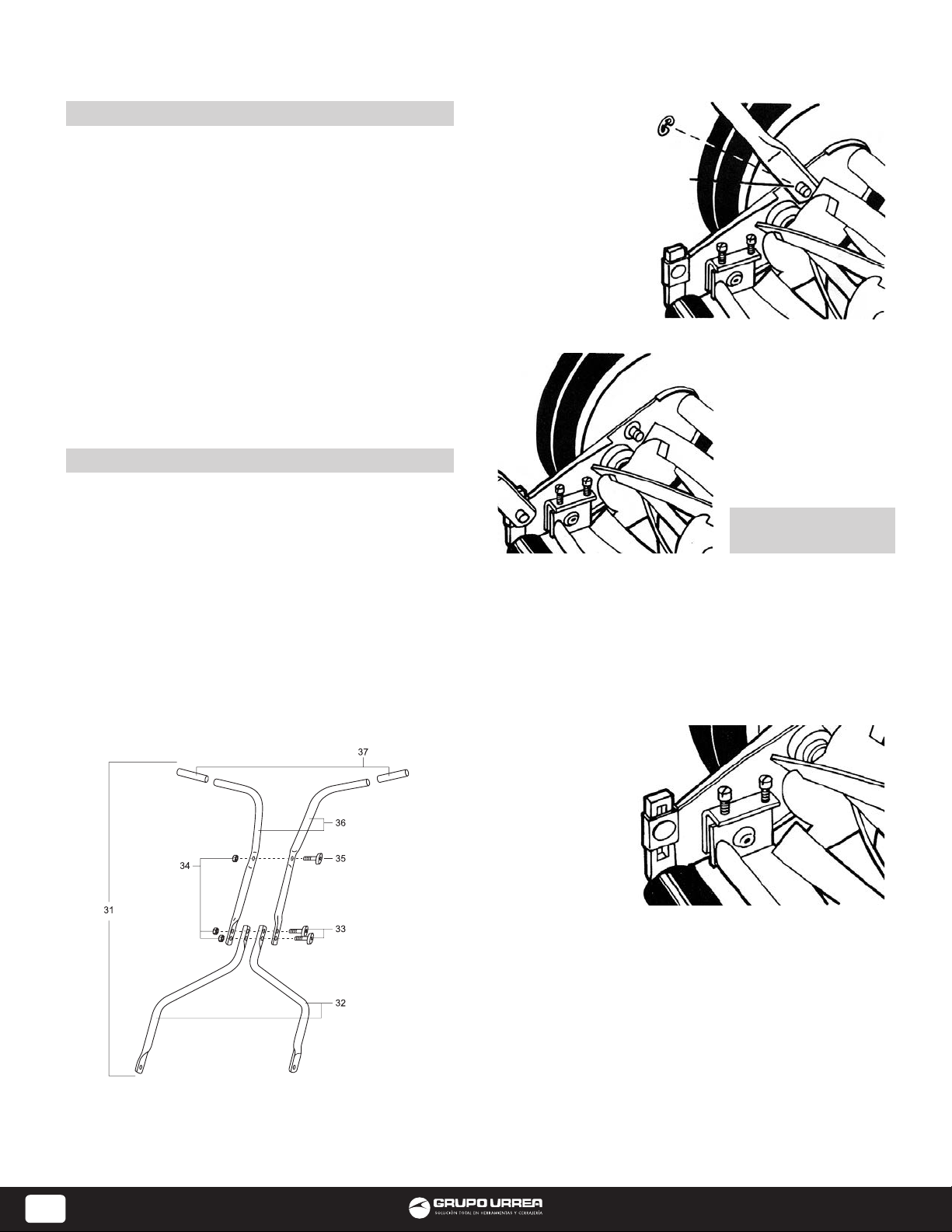
Surtek Podadora 1302720 User manual

130270 130271
Podadora Manual
Handpush Reel Mower
Atención:
Lea, entienda y siga todas las instrucciones de seguridad de este manual antes de usar
esta herramienta.
Warning:
Read, understand and keep the safety rules before using this tool.
Manual de usuario
y garantía
User’s Manual and
Warranty

2
ESPAÑOL
RECOMENDACIONES PARA EL USUARIO
MODO DE ENSAMBLE
• Lea todas las instrucciones antes de usar su podadora
manual SURTEK.
• Inspeccione su césped y asegúrese que no haya desechos,
escombro u otros objetos antes de comenzar a podar.
• Nunca coloque las manos, dedos o pies en el carrete
de la podadora, ya que aunque esta no es operada por
motor, cuando las ruedas se mueven el carrete se mueve
y las cuchillas cortan. Mantenga las manos y pies alejados
de las parte móviles de la podadora.
• No corte el césped si está mojado o resbaladizo.
• No opere la podadora si está descalzo o usando sandalias.
• Al operar la podadora, mantenga sus pies firmes en todo
momento, no corra mientras poda.
• Nunca trate de pasar a la fuerza sobre las ramas, arbustos,
etc. Esto puede causar heridas o lesiones al operador.
• Asegúrese de que su podadora se encuentra en
condiciones adecuadas para el uso seguro. No trate de
operarla si está dañada; repárela o mándela a reparar
primero.
Manijas. La caja de cartón contiene las siguientes
piezas para la manija:
• 2 piezas para la parte superior.
• 2 piezas para la parte inferior.
• Paquete de tornillos y tuercas.
1. Coloque las piezas de la manija de la manera en
que se muestra en la figura 1.
2.Utilizandolostornillosy lastuercascorrespondientes,
acople las piezas inferiores de la manija con las 2
piezas superiores.
3. Acople las 2 piezas superiores de la manija utilizando
los tornillos y tuercas correspondientes.
4. Lubrique la parte interior de los puños de la manija
con agua jabonosa (para facilitar su introducción) y
deslícelo sobre los extremos de la manija.
figura 1
figura 2
figura 3
1. Después de
ensamblar la manija,
sitúe las perforaciones
ubicadas en los
extremos de la parte
inferior de la manija
para que entren en
los postes cortos que
se extienden de las
placas laterales.
2. Una vez que se
haya colocado la
manija sobre los
postes, coloque los
seguros “E” sobre los
postes a fin de prevenir
que se safe la manija.
No intente unir la
manija con los pernos
del montaje de rodillo,
el cual esté situado
en la parte de atrás
de la podadora. ¡Esto
es incorrecto! (vea la
figura 3).
figura 4
Cuidado general. Se requiere de un cuidado
mínimo para asegurar que su podadora funcione sin
inconvenientes.
•Para evitar daños a la podadora o al carrete con
cuchillas, mantenga libre de escombro y desechos el
área que se va a cortar.
• Le sugerimos que aplique con regularidad aceite
(SURTEK WS400). El lubricante WS400 debe aplicarse a
toda la superficie de corte, al eje del cilindro de corte y
a las ruedas.
Ajustes altura
de corte. Estas
unidades pueden
ajustarse para
ofrecer una
altura del corte
entre:
1/2” a 2 1/4”
(12,7 a 57,15 mm)
simplemente
ajustando el
montaje del rodillo. Tenga en mente que se debe
efectuar el mismo ajuste en ambos lados de la podadora.
A medida que siga las instrucciones que se da a
continuación, consulte la figura 4 para obtener
información adicional.
• Para obtener la posición de corte más baja, afloje y
retire las tuercas en ambos lados del montaje del rodillo.
• Vuelva a insertar el tornillo haciendo que pase por
el agujero superior del soporte de plástico del rodillo
y también por el agujero inferior que se encuentra en
la placa lateral de la podadora. Vuelva a apretar las
tuercas en ambos lados del montaje del rodillo.
Instalación de la manija. A medida que siga las
instrucciones que se dan a continuación, consulte la
figura 2 para información adicional.
USO Y
CUIDADO

3
ESPAÑOL
figura 5
Frente
Posterior
Tornillos
de ajuste
• Para obtener la posición de corte más alta, afloje y retire
las tuercas en ambos lados del montaje del rodillo.
• Vuelva a insertar el tornillo, haciendo que pase por el
agujero inferior del soporte de plástico del rodillo y también
por el agujero superior que se encuentra en la placa lateral
de la podadora. Vuelva a apretar las tuercas en ambos lados.
Se pueden obtener otras alturas de corte, pasando el tornillo
por diferentes agujeros.
Ajuste de las cuchillas. La altura de las cuchillas han sido
pre-ajustadas antes de ser empacada.
Con el tiempo, se pueden producir un desalineamiento,
resultado de cuchillas que estén demasiado flojas o
apretadas. Si esto sucede, observará que la unidad corta de
una manera dispareja o que es difícil de empujar.
Todos los ajustes se hacen de la parte trasera de la podadora.
Se pueden ajustar separadamente los extremos de la barra
de corte.
A medida que siga las instrucciones que se dan a continuación
consulte la figura 5 para obtener información adicional.
• La barra de corte (localizada bajo la rueda) gira sobre un
pivote. El tornillo frontal mueve la barra de corte hacia las
navajas.
• El ajuste de los tornillos es muy delicado, 1 1/16 de una
vuelta se considera como un ajuste mayor.
• Antes de apretar uno de los tornillos de ajuste, asegúrese
de aflojar en la misma cantidad el tornillo opuesto.
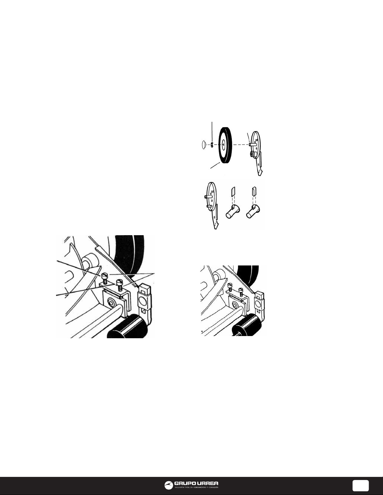
figura 6
figura 7
figura 8
• Inserte una hoja de papel entre la barra de corte y
las cuchillas del cilindro, luego con las manos, de vuelta
cuidadosamente a las cuchillas del cilindro.
Todas las cuchillas deben cortar el papel parejamente
a lo largo de la barra de corte y el cilindro debe girar
uniformemente. Si la podadora produce un corte
intermitente, se debe ajustar el extremo apropiado de
las cuchillas hasta obtener un corte correcto.
Afilado de las cuchillas. Cuando la podadora ha
sido lubricada con (WS400) y ajustada adecuadamente,
el afilado no debe ser necesario por varios años.
Sin embargo, el siguiente
procedimiento permitirá afilar
las cuchillas sin mayor esfuerzo
ni gastos.
• Retire los seguros “E”, las
ruedas y los piñones de ambos
lados de la podadora (vea
figura 6).
• Retire ambas cuñas de las
ranuras rectangulares que
se encuentran en el eje del
cilindro de corte e invierta sus
posiciones (vea figura 7).
• Invierta la posición de los
piñones.
• Coloque el piñón izquierdo
en el extremo derecho del eje
del cilindro y el piñón derecho
en el extremo izquierdo del
eje del cilindro. Vuelva a colocar las ruedas y seguro “E”.
• Ajuste la barra de corte para que la cuchilla tenga
contacto ligero pero firme con las cuchillas del cilindro,
a lo ancho de la barra entera (vea la figura 8).
PRECAUCIÓN: No apriete
demasiado los tornillos de
ajuste, ya que esto puede
dañar la barra de corte. Al
finalizar el ajuste, ambos
tornillos deben quedar bien
apretados.
• Empuje la podadora hacia
atrás sobre una superficie
lisa (tal como una banqueta
o un camino pavimentado).
Continúe haciéndolo hasta
que las cuchillas del cilindro
roten libremente y el borde delantero de la cuchilla de
la barra de corte quede bien pulida.
• Quite las ruedas, invierta los piñones y los trinquetes
para que el borde biselado del trinquete quede a la
derecha.
PRECAUCIÓN: Quite el compuesto del pulimento y los
residuos de las cuchillas del cilindro, de los piñones con
una capa de grasa para cojinete de ruedas y vuelva a
poner las ruedas en los seguros “E”.
NOTA: Se recomienda el uso de un compuesto para
pulimento industrial o de válvulas, con un índice de
granulosidad “grit” entre 100 y 240. Este compuesto se
puede obtener por lo general en cualquier tienda de
artículos industriales o para automóviles. Si se requiere
un afilado profesional contacte algún servicio de
reparación de podadoras.
Aflojar las cuchillas. Se debe alejar la barra de corte del
cilindro de corte.
• Afloje ambos tornillos posteriores en la misma cantidad,
dándoles vuelta en el sentido contrario al de las manecillas
del reloj.
• Apriete ambos tornillos delanteros en la misma cantidad,
dándoles vuelta en el sentido de las manecillas del reloj.
Apretar las cuchillas. Se debe alejar la barra de corte del
cilindro de corte.
• Afloje ambos tornillos delanteros en la misma cantidad,
dándoles vuelta en el sentido contrario al de las manecillas
del reloj.
• Apriete ambos tornillos posteriores en la misma cantidad,
dándoles vuelta en el sentido de las manecillas del reloj.
Comprobación de ajustes.
• Coloque la podadora volteada de cabeza.

4
ENGLISH
USE RECOMMENDATIONS
ASSEMBLY INSTRUCTIONS
• Read all instructions before using your SURTEK
mower.
• Inspect your lawn for any debris or foreign objects
and remove them before mowing.
• Never place your hands, finger or feet inside the reel.
Although not powered by a motor, when the wheels
turns, the reel cuts. Keep your hands of feet away of
the moving parts of the mower.
• Never mow when the grass is wet enough to be
slippery.
• Do not operate the mower while barefoot of wearing
sandals.
• While mowing walk slowly, never run. Always be
sure of your footing when operating the mower.
• Never intentionally strike or ram tree, fences, etc. This
can cause injuries or severaly damage to the mower.
• Make sure your mower is in safe operating conditions.
Do not attempt operate the mower if it damaged,
have it repaired first.
Handles. Enclosed in the box are the following
mower handle parts:
• 2 Upper handlebar pieces.
• 2 Lower pieces.
• Hardware package with screws and nuts.
1. Lay out the parts of the handle as shown in figure
1.
2. Fasten the 2 lower handle pieces to the upper part
of the hancle using its correspondent screw and nut.
3. Fasten the 2 upper handlebar pieces together using
the assembly knobs.
4. Lubricate the inside of the 2 handle grips with
soapy water (for easier application) and slide onto the
handle.
figure 1
figure 2
figure 3
1. After assembling
the handle, fit the
holes at the endo of
the lower portion of
the handle on the
left and right side.
Over the short posts
extendin out from
the side plates.
2. When the
handles is in place
over the posts, snap
the “E” rings onto
the slotted posts
on both sides to
prevent the handle
from coming off.
DO NOT attempt to
attach the handle to
the bolts on the roller
assembly at the rear
of the mower. This
is incorrect! (refer to
figure 3).
figure 4
General care. Minimum care is required to assure
smooth operation of your mower.
•To avoid damage to the mower or cutting blades,
keep the area to be mowed free from any debris.
• We suggest a routine application of SURTEK WS400
oil or lubricant. This should be applied to all cutting
surfaces, the cutting reel axle shaft and wheels.
Cutting height adjustments. These unit can be
adjusted to offer
a cutting height
range from:
1/2” to 2 1/4”
(12,7 to 57,15 mm)
simply by
adjusting the
roller assembly.
Keep in mind
that the same
adjustment must
be applied on
both sides of the
mower.
As you follow the instructions below, refer to figure
4 for more information.
• To achieve the lowest cutting position, loosen and
remove the nuts on both sides of the roller assembly.
• Place the screw back; pass it through the top hole of
the plastic roller bracket and the bottom hole of the
mower side plate. Fasten nuts on both sides.
Other cutting heights can be obtained by positioning
the bolts through other hole locations.
Attaching the handle to the mower. As you follow
the instructions below, refer to figure 2 for more
information.
USAGE AND
CARE

5
ENGLISH
figure 5
Front
Rear
Adjusting
screws
• To achieve the highest cutting position, loosen and
remove the nuts on both sides of the roller assembly.
• Place the screw back; pass it through the bottom
hole of the plastic roller bracket and the top hole of
the mower side plate. Fasten nuts on both sides.
Other cutting heights can be obtained by positioning
the bolts through other hole locations.
Mower blade adjustment. The height of the blades
have been pre-adjusted before been packed.
Misalignment can occur resulting in blades that are
too loose or too tight. If this happens, you will notice
a rough, uneven cut or a hard-pushing mower.
All adjustments are made frlom the rear of the mower.
Each end of the cutting bar can be adjusted separately.
As you follow the instructions below, refer to figure 6
for more information.
• The cutting bar blade (located under the reel) turns
under a pivot. The front screw move the cutter bar
toward the blades.
• Adjusting the screw is a very sensitive procedure,
1/16 of a turn is considered a major adjustment.
• Before tightening one adjusting screw, be sure to
loosen the opposing screw an equal amount.
figure 6
figure 7
figure 8
• Insert a piece of paper between the cutter bar and the
reel blades, and carefully turn the reel blades by hand.
All blades should slice the paper evenly the entire length
of the cutter bar while the reel turns smoothly.
It the mower has a intermittent cut, adjustment should be
made to appropriate side of the blades to attain proper
cutting actions.
Sharpening the cutting blades. When the mower is
properly lubricated and adjusted, sharpening should not
be necessary for several years.
However, the following steps
will allow you to do the
procedure yourself at relatively
little expense.
• Remove the “E” ring, wheels
and pinion from both sides of
the mower (refer to figure 6).
• Remove both pawls from the
rectangular slots in reel shaft
and reverse their positions
(refer to figure 7).
• Reverse the placement of the
pinion gears.
• Place the left pinion on the
right end of the reel shaft and
the right pinion on the left end
of the reel shaft. Replace the
wheel and “E” rings.
• Spread a thin layer of lapping
compound on the front edge reel blades.
• Adjust the cutter bar so that cutter bar blade has light
but firm contact with the reel blades across the full widht
of the cutter bar (refer to figure 8).
CAUTION: Do not overtighten
the addjusting screw, as this
could damage the cutter bar.
Both screws must be tight on
the final adjustment.
• Push the mower backward
on a smooth surface (such as a
sidewalk or paved driveway).
Continue to do this until the
reel blades rotate relatively free
and front edge of the cutter bar
blade is polished.
• Remove wheels; reverse points
and pawls so that the beveled edge of the pawl is on the
right.que las cuchillas del cilindro roten libremente y el
borde delantero de la cuchilla de la barra de corte quede
bien pulida.
• Quite las ruedas, invierta los piñones y los trinquetes para
que el borde biselado del trinquete quede a la derecha.
CAUTION: Clean any grinding compound or debris from the
cutter bar blade, reel blades, pinions and pawls. Lubricate
axle and pinions with a light film of wheelbearing grease
and replace wheels and “E” rings.
NOTE: It is recommended to use an industrial or valve
lapping compound between 100-240 grit. This is usually
available at an industrial or automotive supply store. If
professional sharpening is required, consult any lawn
mower repair services.
Loosening blades. The cutting bar blades must be
moved further from the cutting reel.
• Loosen both back screws equal by turning them
counterclockwise.
• Tighten both front screw equally by turning them
clockwise.
Tightening blades. The cutting bar blades must be
moved further from the cutting reel.
• Loosen both front screws equally by turning them
conterclockwise.
• Tighten both back screw equally by turning them
clockwise.
Check adjustments.
• Turn mower upside down.

6
LISTA DE PARTES Y DESPIECE / PART LIST AND EXPLODED VIEW
130270
Parte / Part Descripción / Description
1A
1B
2
3
4
5
6
7
8
9
10
11
11A
12
13
13A
14
15
16
16A
17
18
19
20
21
22
23
24
25
26
26A
27
28
29
30
31
Cojinete / Ball cup
Cojinete / Ball cup
Balero / Ball bearing assembly
Taza cónica / Bearing cone
Resorte de ajuste del cilindro / Spring reel adjustment
Arandela de protección contra el polvo / Dust washer
Arandela de cojinete / Bearing washer
Cuña / Pawl
Montaje de cilindro / Reel assembly
Aro en “E” del eje / Snap ring
Tapa de la rueda / Hub cap
Eje / Axe
Tuerca hexagonal 3/8” / Hex nut 3/8”
Rin / Rim
Llanta / Tire
Montaje de la rueda y la llanta / Wheel and tire assembly
Perno de cabeza hexagonal / Hex head bolt
Placa de la cubierta / Cover plate
Placa lateral izquierda / Left side plate
Placa lateral derecha / Right side plate
Anillo de retención / Retaining rng
Barra de torsión / Torsion bar
Engranaje de piñón izquierdo / Left pinion gear
Tornillo de ajuste (incluido en 16 y 16A) / Adjustment screw
Engranaje del piñón derecho / Right pinion gear
Tornillo de la barra de corte 3/8” x 1 1/8” / Cutter bar bolt 3/8” x 1 1/8”
Tuerca hexagonal / Hex nut
Soporte del rodillo / Roller bracket
Perno de carruaje 5/16” / Carriage bolt
Barra de corte / Cutter bar
Buje / Cutter bar stud
Sección de rodillo / Roller section
Espaciador del rodillo / Roller spacer
Tubo del rodillo / Roller tube
Sujetador del soporte del rodillo / Roller bracket clamp
Montaje del rodillo / Roller assembly

7
LISTA DE PARTES Y DESPIECE / PART LIST AND EXPLODED VIEW
130271
Parte / Part Descripción / Description
1A
1B
2
3
4
5
6
7
8
9
10
11
11A
12
13
13A
14
15
16
16A
17
18
19
20
21
22
23
24
25
26
26A
27
28
29
30
31
Cojinete / Ball cup
Cojinete / Ball cup
Balero / Ball bearing assembly
Taza cónica / Bearing cone
Resorte de ajuste del cilindro / Spring reel adjustment
Arandela de protección contra el polvo / Dust washer
Arandela de cojinete / Bearing washer
Cuña / Pawl
Montaje de cilindro / Reel assembly
Aro en “E” del eje / Snap ring
Tapa de la rueda / Hub cap
Eje / Axe
Tuerca hexagonal 3/8” / Hex nut 3/8”
Rin / Rim
Llanta / Tire
Montaje de la rueda y la llanta / Wheel and tire assembly
Perno de cabeza hexagonal / Hex head bolt
Placa de la cubierta / Cover plate
Placa lateral izquierda / Left side plate
Placa lateral derecha / Right side plate
Anillo de retención / Retaining rng
Barra de torsión / Torsion bar
Engranaje de piñón izquierdo / Left pinion gear
Tornillo de ajuste (incluido en 16 y 16A) / Adjustment screw
Engranaje del piñón derecho / Right pinion gear
Tornillo de la barra de corte 3/8” x 1 1/8” / Cutter bar bolt 3/8” x 1 1/8”
Tuerca hexagonal / Hex nut
Soporte del rodillo / Roller bracket
Perno de carruaje 5/16” / Carriage bolt
Barra de corte / Cutter bar
Buje / Cutter bar stud
Sección de rodillo / Roller section
Espaciador del rodillo / Roller spacer
Tubo del rodillo / Roller tube
Sujetador del soporte del rodillo / Roller bracket clamp
Montaje del rodillo / Roller assembly

SELLO DEL DISTRIBUIDOR FECHA / /
Poliza de garantía. Este producto está garantizado por URREA HERRAMIENTAS PROFESIONALES, S.A. DE C.V.,
km 11,5 Carr. A El Castillo, 45680 El Salto, Jalisco. UHP900402Q29, Teléfono 01 33 3208-7900 contra defectos de
fabricación y mano de obra con su reposición o reparación sin cargo por el periodo de 100 años.
Para hacer efectiva esta garantía, deberá presentar el producto acompañado de su comprobante de compra en el
lugar de adquisición del producto o en el domicilio de nuestra planta mismo que se menciona en el primer párrafo
de esta garantía. En caso de que el producto requiera de partes o refacciones acuda a nuestros distribuidores
autorizados. Los gastos que se deriven para el cumplimiento de esta garantía serán cubiertos por Urrea Herramientas
Profesionales, S.A. de C.V.
Esta garantía no será efectiva en los siguientes casos:
a).- Cuando la herramienta se haya utilizado en condiciones distintas a las normales.
b).- Cuando el producto hubiera sido alterado de su composición original o reparado por personas no autorizadas
por el fabricante o importador respectivo.
This product has a lifetime warranty by Urrea Herramientas Profesionales S.A. de C.V. against any manufacturing
defect, with its repair or replacement during its life expectancy.
The warranty is not applicable if the product does not show the URREA brand, if the product is worn out by its daily
use, shows signs of abuse, damage, its original composition has been altered, or specifies a different warranty.
In order to make the warranty effective, the product must be taken to the company or to the place of purchase along
with its receipt.
IMPORTADO POR / IMPORTED BY: URREA HERRAMIENTAS PROFESIONALES S.A. DE C.V. km 11,5 Carretera a El
Castillo, El Salto, Jalisco, México C.P. 45680 R.F.C. UHP900402Q29 Tel. 01 (33) 3208-7900 Made in China / Hecho
en China 04-K14
130270
130271
This manual suits for next models
1
Table of contents
Other Surtek Lawn Mower manuals
Popular Lawn Mower manuals by other brands

Encore
Encore EW36FS481VH Operator's manual

Husqvarna
Husqvarna TC 242 Euro instruction manual

Jonsered
Jonsered LT2217CMA Spare parts

Stiga
Stiga MJ 66 Operator's manual

Cub Cadet
Cub Cadet 20HP Enforcer 44, 22HP Enforcer 48, 23HP Enforcer... Operator's and service manual

Ryobi
Ryobi RLM46160PB Original instructions