SWEENEY MX1E User manual

Instruction Sheet
MX1E and MX1E-2
Mini Electric Consoles
L2135 Rev. D 04/08
1.0 IMPORTANT RECEIVING INSTRUCTIONS
Visually inspect all components for shipping damage.
Shipping damage is not covered by warranty. If shipping
damage is found, notify carrier at once. The carrier is
responsible for all repair and replacement costs resulting
from damage in shipment.
SAFETY FIRST
2.0 SAFETY ISSUES
Read all instructions, warnings, and cautions
carefully. Follow all safety precautions to
avoid personal injury or property damage
during system operation. Sweeney cannot be responsible
for damage or injury resulting from unsafe product use,
lack of maintenance or incorrect product and/or system
operation. Contact Sweeney when in doubt as to the
safety precautions and operations. Failure to comply with
the following cautions and warnings could cause
equipment damage and personal injury.
A CAUTION is used to indicate correct operating or
maintenance procedures and practices to prevent
damage to, or destruction of equipment or other property.
A WARNING indicates a potential danger that requires
correct procedures or practices to avoid personal injury.
A DANGER is only used when your action or lack of
action may cause serious injury or even death.
WARNING: Wear proper personal protective gear
when operating hydraulic equipment.
DANGER: To avoid personal injury keep hands
and feet away from cylinder and workpiece
during operation.
Never set the relief valve to a higher pressure than
the maximum rated pressure of the pump. Higher
settings may result in equipment damage and/or
personal injury.
WARNING: The system operating pressure must not
exceed the pressure rating of the lowest rated
component in the system. Install pressure gauges in
the system to monitor operating pressure. It is your window
to what is happening in the system.
CAUTION: Avoid damaging hydraulic hose. Avoid
sharp bends and kinks when routing hydraulic
hoses. Using a bent or kinked hose will cause severe
back-pressure. Sharp bends and kinks will internally
damage the hose leading to premature hose failure.
1325 94146772950
1000
1025
975
7124
7300
6950
1375
1400
1350
9766
9943
9593
4321600
2407325
5372750
6071850
925
900
875 6248
6600
6421
825
800
775
5897
5545
5721
PSIFt.Lb
675
725
700
4848
5193
5021
350
375
2579
2993
1125 8000
1225 8707
1250
1300
1275
9236
9062
8886
1175
1200
1150 8179
8357
8531
Ft.Lb PSI
1050
1100
1075
7476
7828
7650
4497
4669
625
650
RSL2
1014125
1710225
275
300
250
2055
2229
1883
175
150
200
1364
1186
1538
Ft.Lb PSI
2921400
3621500
4145
3972
3800
550
575
525
3100
3448
3276
425
475
450
Ft.Lb PSI
8909
62251850 2700
9384
9847
9541
6384
6543
6700
1900
1950
2000
2850
2900
3000
6857
PSI
7331
7175
7016
7806
7650
8121
8279
7962
7489
8752
49621450 2200
5438
5279
5752
5911
5594
5121
6069
1650
1700
1750
1800
1550
1600
1500
2400
2450
2500
2650
2350
2300
2250
2438
2597
4489
4806
4648
Ft.Lb
1300
1400
1350
650
700
PSI Ft.Lb
2150
2100
2050
1200
1250 4331
4175
1175
1333
1491
1648
1806
1965
2122
2279
450
500
600
550
250
400
300
350
1150
1100
1000
1050
3543
3857
3700
4016
850
800
900
950
3070
2911
3228
3384
1016
Ft.Lb
200
Ft.Lb
750
PSI
RSL4
PSI
2753
BEFOREUSING
ALLINSTRUCTIONS
READAND UNDERSTAND
TOAVOID INJURY
WARNING
STOP
MX1E and MX1E-2 consoles are designed for use with double-acting torque wrenches and remote pendant operation.
Consoles are equipped with glycerine-filled pressure gauges and adjustable pressure relief valves. The heat exchanger
prevents heat buildup, and the time-out circuit stops the motor after 15 seconds of idle running.

Do not drop heavy objects on hose. A sharp
impact may cause internal damage to hose wire
strands. Applying pressure to a damaged hose
may cause it to rupture.
IMPORTANT: Do not lift hydraulic equipment by
the hoses or swivel couplers. Use the carrying
handle or other means of safe transport.
CAUTION: Keep hydraulic equipment away from
flames and heat. Excessive heat will soften
packings and seals, resulting in fluid leaks. Heat
also weakens hose materials and packings. For optimum
performance do not expose equipment to temperatures of
65°C [150°F] or higher. Protect hoses and cylinders from
weld spatter.
DANGER: Do not handle pressurized hoses.
Escaping oil under pressure can penetrate the skin,
causing serious injury. If oil is injected under the
skin, see a doctor immediately.
WARNING: Only use consoles in a coupled
system.
WARNING: Do not use hoses, fittings, or couplers
with pressure ratings below 10,000 psi [700 bar].
Equipment with inadequate pressure rating can fail
and cause personal injury, property or equipment damage.
CAUTION: To avoid personal injury, do not use
electric consoles in an explosive atmosphere.
Adhere to all local and national electrical codes.
CAUTION: To help prevent console failure, check
reservoir fluid prior to console operation. If fluid
level is low, add oil. Always be sure tools are fully
retracted before adding fluid to the reservoir.
CAUTION: To prevent damage to console electric
motor, check specifications and motor plate data.
CAUTION: To prevent oil spillage, tighten vent/fill
plug when shipping or storing console.
3.0 SPECIFICATIONS — See table below.
4.0 INSTALLATION
1. Check oil level in reservoir. Oil level should be 1 inch
below vent/fill plug opening. If necessary, add
hydraulic oil to bring oil level up to 1 inch below the
vent/fill opening.
NOTE: Use only approved hydraulic oil. Use of any other
oils or fluids may damage console or seals and will
void the warranty on your console.
2. Vent reservoir by turning vent/fill plug 1 to 2 turns
counter-clockwise from fully closed position.
3. Be sure the electrical power source is the correct one
for your console. See specification table for electrical
power source specification.
2
®
Model MX1E-1 MX1E-2
Electrical Power
Source
Motor Rating 1/2 HP Universal
9 Amps at 10,000 psi [700 bar] (@115 VAC)
4.5 Amps at 10,000 psi [700 bar] (@230 VAC)
Weight with Oil 52.5 lbs [23,9 kg]
Operating Pressure 0 - 10,000 psi [0 - 700 bar]
Flow vs. Pressure 200 in3/min at 0 - 700 psi [3,3 l/min at 0 - 50 bar]
18 in3/min at 10,000 psi [0,3 l/min at 700 bar]
Max. Temperature of 150°F [65° C]
Oil
Reservoir Capacity 0.75 gal [2,8 l] total
0.50 gal [1,9 l] useable
Noise 85-89 dBA
Extension Cords 1 - 50 ft [0-17 m] = 16 AWG
50 - 100 ft [17-34 m] = 14 AWG
9 Amp/115 V, 1-phase, 50/60 Hz Grounded 4.5 Amp/220 V, 1-phase, 50/60 Hz
Specification Table

3
4. Loosen locknut and back out (turn counter-clockwise)
relief valve to prevent unintended pressure build-up.
No tools are needed to adjust the relief valve. See
Figure 1.
4.1 Hose Connections
1. Couple hoses to console outlet manifold as shown in
Figure 2. BE SURE to use a Sweeney hose marked
“10,000 psi [700 bar] max.” Rotate coupler locking
rings. “A” port is for advancing and “B” port is for
retracting the piston in the torque wrench. Consoles
are supplied with the specified coupling halves
already connected to the console ports to prevent
incorrect coupling of hoses to wrench.
2. Couple hoses to torque wrench as shown in Figure 3.
Rotate coupler lock rings. When using the Sweeney
console and torque wrench combination, Sweeney
hoses and couplers are designed so that the console
advance port can only be connected to the wrench
advance port, and the console retract port can only be
connected to the wrench retract port.
WARNING: To ensure proper operation, avoid
kinking or tightly bending hoses. If a hose becomes
kinked or otherwise damaged, it MUST BE replaced.
Damaged hoses may rupture at high pressure causing
personal injury.
WARNING: Attempting to couple a hose to the
console or torque wrench while coupler is under
pressure can result in fluid leakage or personal injury.
5.0 OPERATION
IMPORTANT: When possible,
a single user should
operate the torque wrench and console
. This can
prevent accidental activation of the console while
the operator is positioning the wrench.
1. Check all system fittings and connections to be sure
they are tight and leak free.
2. Check oil level in reservoir. Oil level should be 1 inch
below vent/fill plug opening.
3. Vent reservoir by turning vent/fill plug 1 to 2 turns
counter-clockwise from fully closed position.
CAUTION: Operating console without a sufficient
amount of oil will damage the console. Add oil only
when system components are retracted or system
will contain more oil than the console reservoir can hold.
CAUTION: Reservoir must be vented whenever
console is running. If not, a vacuum may develop in
the reservoir, preventing the flow of oil through the
console.
4. Be sure the console switch is “OFF.” See Figure 4.
1325 94146772950
1000
1025
975
7124
7300
6950
1375
1400
1350
9766
9943
9593
4321600
2407325
5372750
6071850
925
900
875 6248
6600
6421
825
800
775
5897
5545
5721
PSIFt.Lb
675
725
700
4848
5193
5021
350
375
2579
2993
1125 8000
1225 8707
1250
1300
1275
9236
9062
8886
1175
1200
1150 8179
8357
8531
Ft.Lb PSI
1050
1100
1075
7476
7828
7650
4497
4669
625
650
RSL2
1014125
1710225
275
300
250
2055
2229
1883
175
150
200
1364
1186
1538
Ft.Lb PSI
2921400
3621500
4145
3972
3800
550
575
525
3100
3448
3276
425
475
450
Ft.Lb PSI
890962251850 2700
9384
9847
9541
6384
6543
6700
1900
1950
2000
2850
2900
3000
6857
PSI
7331
7175
7016
7806
7650
8121
8279
7962
7489
8752
49621450 2200
5438
5279
5752
5911
5594
5121
6069
1650
1700
1750
1800
1550
1600
1500
2400
2450
2500
2650
2350
2300
2250
2438
2597
4489
4806
4648
Ft.Lb
1300
1400
1350
650
700
PSI Ft.Lb
2150
2100
2050
1200
1250 4331
4175
1175
1333
1491
1648
1806
1965
2122
2279
450
500
600
550
250
400
300
350
1150
1100
1000
1050
3543
3857
3700
4016
850
800
900
950
3070
2911
3228
3384
1016
Ft.Lb
200
Ft.Lb
750
PSI
RSL4
PSI
2753
Figure 1
Figure 2
Figure 3
B
A
Console
SWEENEY 10,000 PSI [700 BAR] MAX.
B
Figure 4
ON
OFF
Momentary Advance
(Can be used instead
of pendant.)
(Activates electrical
Circuit only.)
1325 94146772950
1000
1025
975
7124
7300
6950
1375
1400
1350
9766
9943
9593
4321600
2407325
5372750
6071850
925
900
875 6248
6600
6421
825
800
775
5897
5545
5721
PSIFt.Lb
675
725
700
4848
5193
5021
350
375
2579
2993
1125 8000
1225 8707
1250
1300
1275
9236
9062
8886
1175
1200
1150 8179
8357
8531
Ft.Lb PSI
1050
1100
1075
7476
7828
7650
4497
4669
625
650
RSL2
1014125
1710225
275
300
250
2055
2229
1883
175
150
200
1364
1186
1538
Ft.Lb PSI
2921400
3621500
4145
3972
3800
550
575
525
3100
3448
3276
425
475
450
Ft.Lb PSI
890962251850 2700
9384
9847
9541
6384
6543
6700
1900
1950
2000
2850
2900
3000
6857
PSI
7331
7175
7016
7806
7650
8121
8279
7962
7489
8752
49621450 2200
5438
5279
5752
5911
5594
5121
6069
1650
1700
1750
1800
1550
1600
1500
2400
2450
2500
2650
2350
2300
2250
2438
2597
4489
4806
4648
Ft.Lb
1300
1400
1350
650
700
PSI Ft.Lb
2150
2100
2050
1200
1250 4331
4175
1175
1333
1491
1648
1806
1965
2122
2279
450
500
600
550
250
400
300
350
1150
1100
1000
1050
3543
3857
3700
4016
850
800
900
950
3070
2911
3228
3384
1016
Ft.Lb
200
Ft.Lb
750
PSI
RSL4
PSI
2753
Vent/Fill Plug
Relief Valve
A

4
5. Plug power cord into outlet. Use correct power source.
See page 2 for specifications. Keep power cords short
to avoid power losses. The console motor may
function at lower voltage, but motor speed and oil flow
will be reduced and motor may become damaged.
6. Press “I” on the console switch to turn power on.
Pressing “I” activates the electrical circuit, but does
not turn the console motor on. The console motor is
activated by the pendant switch.
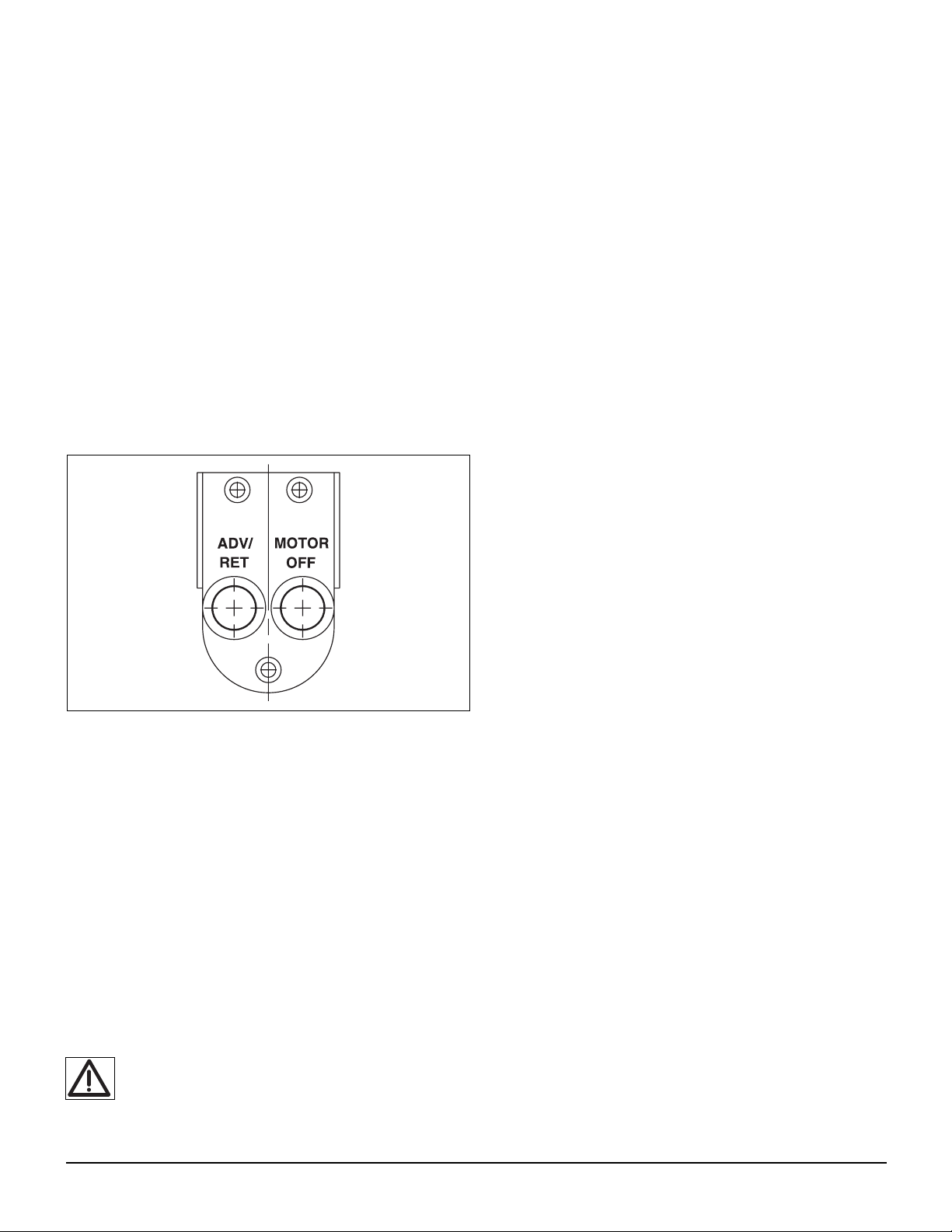
5.1 Pendant Operation
The pendant has two push button switches (See Figure
5). Press momentary push button (1) for “Advance.”
Release “Advance” and the torque wrench piston will
retract. Use the (2) “Motor off” push button if you need to
shut the unit off at any time.
NOTE: The electric motor keeps running after the pendant
is released. Within 15 seconds of your last command
from the pendant, the motor will time-out and turn
off, preventing heat build-up and unnecessary wear.
5.2 Air Removal
When the wrench is first connected to the console, air will
be trapped in the components.To ensure smooth and safe
operation, remove air by cycling wrench several times
without load. Cycle until wrench advances and retracts
without hesitation.
Check oil level before operation.
NOTE: Perform Air Removal and Pressure (Torque)
Adjustment:
1. during initial operation or start-up.
2. when connecting a different wrench to the console.
3. when changing torque value (pressure adjustment
only).
5.3 Pressure (Torque) Adjustment
WARNING: Make these adjustments BEFORE
putting torque wrench on nut or bolt head. The
console pressure setting may be above the pressure
needed to provide the required torque for your application.
Exceeding required torque will cause equipment damage
and may lead to serious personal injury.
REFER TO TORQUE WRENCH INSTRUCTIONS FOR
WRENCH OPERATING PROCEDURE.
1. The console is supplied with a pressure gauge
installed. See torque wrench instructions for amount
of pressure required to produce desired torque. Note
that the maximum pressure varies for different
wrenches and accessories.
2. Loosen locknut and back out relief valve to prevent
unintended pressure build-up. See Figure 1.
3. Turn the console on.
4. Press and hold the “Advance” push button and read
pressure gauge.
5. While holding the “Advance” push button, turn relief
valve in (clockwise) to increase pressure or out
(counter-clockwise) to decrease maximum pressure.
Repeat until correct pressure is obtained.
NOTE: When adjusting the pressure while the pump is
running the pressure must always start out at a
lower setting and then adjust the pressure
upwards.
6. Tighten locknut on relief valve to maintain setting.
7. Run the console several times to test the pressure
setting.
6.0 MAINTENANCE
6.1 Adding oil to the console
Check reservoir hydraulic oil level every 40 hours of
operation. Add hydraulic oil when necessary to bring oil
level up to 1 inch below the vent/fill opening.
6.2 Changing the oil
Completely drain the reservoir after every 100 hours of
operation. If console is operated in very dusty areas or at
high temperatures, drain and refill after 50 hours of
operation.
1. Remove the vent/fill plug from reservoir.
2. Tip the console until all old oil has drained out.
3. Add new hydraulic oil through vent/fill opening until
the oil level is 1 inch below the vent/fill opening.
Reservoir capacity is 0.75 gallon (2.8 liters).
4. Replace the fill plug.
5. DISPOSE OF USED OIL PROPERLY
6.3 Cleaning the reservoir
The reservoir can be removed for cleaning, and should be
cleaned at least once a year.
1. Remove vent/fill plug from reservoir. Tip the console
until all old oil has drained out.
2. DISPOSE OF USED OIL PROPERLY.
3. You will need to remove the blue shroud to get at the
screws that hold the console to the reservoir. Use a
hex wrench to remove the six screws securing shroud
to the reservoir.
4. Disconnect wire(s) from solenoid valve. Mark wires
before disconnecting them from the 4-way valve.
Figure 5, Pendant

5
5. Lift shroud from reservoir. DO NOT remove the foam
insulation. Use care to avoid damaging wires or
pulling wire connections off terminals.
6. Remove 8 screws holding console to reservoir.
7. Lift console from reservoir using care to avoid
damaging pick-up screens.
8. Remove gasket and discard.
9. Thoroughly clean the reservoir with solvent. Never
use water.
10. Use a soft bristle brush to clean intake screens. Rinse
with solvent.
11. Install a new gasket.
12. Position the coverplate on the reservoir. Make certain
that the gasket is visible all the way around the
coverplate.
13. Secure console to reservoir.
14. Place shroud over motor with shroud handle facing
valve side of console.
15. Install the six mounting screws.
16. Reconnect wire(s) to solenoid valve.
17. Before reinstalling the heat exchanger, use
compressed air to blow dirt out of the heat exchanger.
18. Fill reservoir to inch below the vent/fill opening with
new hydraulic oil. Reservoir capacity is 0.75 gallon
(2,8 liters).
6.4 Motor Brushes
Check the electric motor brushes at least once every two
years. For pumps in heavy usage applications, check the
brushes at least once every six months.
DANGER: To avoid possible electrocution, pump
must be completely disconnected from electrical
power before brush servicing is attempted.
Problem Possible Cause Solution
Motor current draw is
excessive.
Noisy console operation.
Console fails to maintain
pressure.
Low oil output.
Console builds pressure
slowly or erratically.
Console is overheating.
Defective motor.
By-pass valve malfunction.
Damaged or worn piston blocks.
Piston block piston is sticking.
Springs or balls are damaged.
Oil leaking from one or more
components within the reservoir.
Console component parts leaking.
By-pass valve malfunctioning.
Oil intake screens on piston
blocks are clogged.
Low oil level.
Internal leakage in valve.
Nylon tubing to heat exchanger is
disconnected.
Thermostat malfunction.
Remove the motor. Test and replace if necessary.
Inspect and test by-pass valve if required. Valve is preset. If
damaged or incorrectly set, replace.
Test and inspect the piston blocks. Replace
if necessary.
Remove the piston blocks. Inspect and replace as required.
Piston blocks are non-serviceable.
Remove the console from the reservoir and back pressure
test it. Contact Sweeney for the test procedure.
Perform back pressure test to isolate leaks.
Test and inspect by-pass valve. Replace and
set if necessary.
Inspect intake screens. Flush all components of
contamination. Replace damaged components.
Fill reservoir to proper level.
Disassemble valve and replace worn or damaged parts.
Reconnect nylon tubing under pumping unit. Tubing will
click into place when it is properly connected.
Replace thermostat.
If your console requires repair work, contact your Sweeney Authorized Service Station.
TROUBLESHOOTING CHART

6
7.0 TROUBLESHOOTING (See Chart on Page 5)
The Troubleshooting Chart is intended as a guide to help you
diagnose and correct various possible pump problems.
Only qualified hydraulic technicians should troubleshoot and
service the pump. For repair service, contact the Sweeney
authorized service station in your area.
7.1 Circuit Breaker (Pumps with Date Code “F” and Later)
In the event of an electrical overload, the pump circuit breaker
will trip. After investigating and correcting the source of the
overload, push the circuit breaker button to reset.
7.2 Fuses (Pumps with Date Code “F” and Later)
Internal fuses protect the primary and secondary circuits of the
control transformer. If a fuse blows, investigate and correct the
source of the failure. Then, replace the blown fuse with a new
fuse of the correct rating. For fuse ratings, refer to the Repair
Parts Sheet for your pump model.
WARNING: Always disconnect electrical power
before replacing fuses.
8.0 TEST STANDARDS
8.1 Canadian Standards Association (CSA)
Where specified, pump assemblies meet the design assembly
and test requirements of CSA, the Canadian Standards
Association (Refer to CAN/CSA — C22.2 No. 68-92, Motor
operated appliances).
8.2 Conformité Européene (CE)
Where specified, an EC Declaration of Conformity and CE
marking of product is provided. These products conform to
European Standards EN982:1996, EN1050:1998 and EN-ISO-
12100-1&2:2003, and to EC Directives 2006/42/EC, 97/23/EC,
2004/108/EC, 2006/95/EC and 97/23/EC.
NOTES:

LIMITED WARRANTY
Sweeney warrants to the original purchaser only that the Product manufactured by it will be free from
defects in design, materials and workmanship for three years (see exception below) from the date on
which the Product is delivered to the original purchaser. EXCEPT AS STATED IN THIS LIMITED
WARRANTY, SWEENEY DOES NOT MAKE AND DISCLAIMS ALL EXPRESS OR IMPLIED
WARRANTIES INCLUDING, BUT NOT LIMITED TO, THE MERCHANTABILITY OF THE PRODUCT, ITS
FITNESS FOR A PARTICULAR PURPOSE, ITS DESIGN, CONDITION OR WORKMANSHIP.
Sweeney's obligation under this warranty is limited to replacing or restoring (at Sweeney's election) any
Product that is returned intact to it, or to one of its authorized service stations with transportation
charges prepaid, within the warranty period, and that it is disclosed, to Sweeney's satisfaction, to be
defective after its examination. The original purchaser is responsible for maintaining and replacing field
serviceable items such as drive squares, fuses, heater coils, filter elements and fluids. The field
serviceable items are not warranted by Sweeney. This warranty shall not apply to any Product that has
been repaired or altered outside of the Sweeney factory or authorized service stations, or has been
subject to misuse or abuse, negligence or accident, or has been installed or used not in accordance with
instructions furnished with the product by Sweeney.
SWEENEY WILL NOT BE LIABLE FOR ANY SPECIAL, INDIRECT, INCIDENTAL OR
CONSEQUENTIAL DAMAGES OF ANY CHARACTER AS A RESULT OF A BREACH OF ITS LIMITED
WARRANTY, INCLUDING WITHOUT LIMITATION: INCONVENIENCE, TRANSPORTATION COSTS,
LOSS OF PROFITS, PROPERTY DAMAGE OR LOST PRODUCTION, WHETHER SUFFERED BY THE
ORIGINAL PURCHASER OR ANY THIRD PARTY. Sweeney's maximum liability under any
circumstances will be the purchase price of the product paid by the original purchaser. Sweeney neither
assumes nor authorizes any person to assume for it any other or greater liability in connection with the
sale of its products.
Any provision in this limited warranty, including any provision limiting or excluding legal remedies or
warranties of merchantability or fitness for purpose, is not applicable where expressly prohibited by local
law, but only to the extent so prohibited.
Any action for breach of this warranty, regardless of the legal theory of the action, must be brought within
one year after the date of breach.
Documentation of the date of delivery to the original purchaser is required with all requests for warranty.
Contact Customer Service for a "Return Material Authorization" (RMA) number and shipping
instructions. Products returned without an RMA number will not be accepted.
* Exception to warranty period: The warranty period for Slect-A-Torq® tools and accessories
used in rental fleets or by bolting services is six months.

A DOVER DIVERSIFIED COMPANY
359 Inverness Drive South, Suite B
Englewood, Colorado 80112-5816
Telephone: 303-792-5240 • Telex: 4990571
Telefax: 303-792-5124 • Toll Free: 1-800-448-2524
This manual suits for next models
1
Table of contents