manuals.online logo
Brands
  1. Home
  2. •
  3. Brands
  4. •
  5. Sylvania
  6. •
  7. TV
  8. •
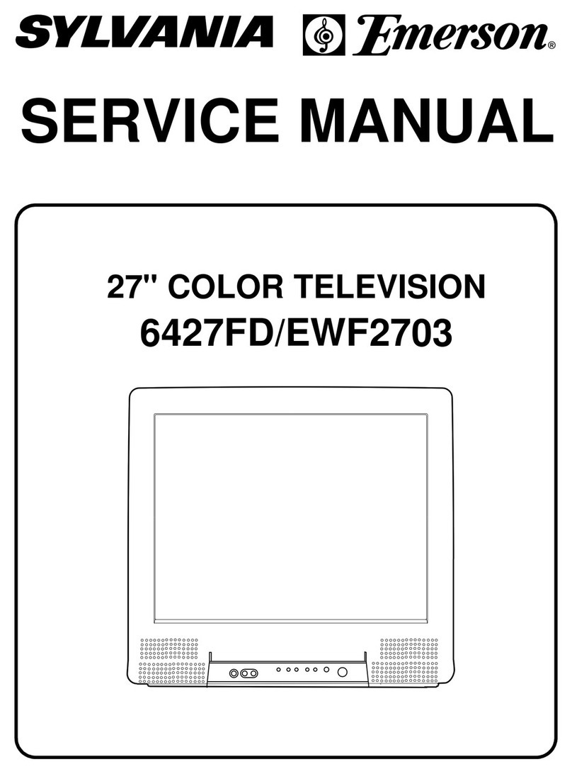
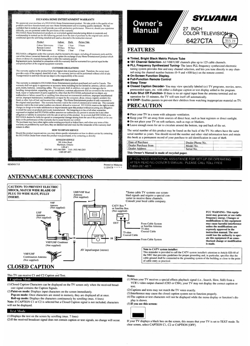
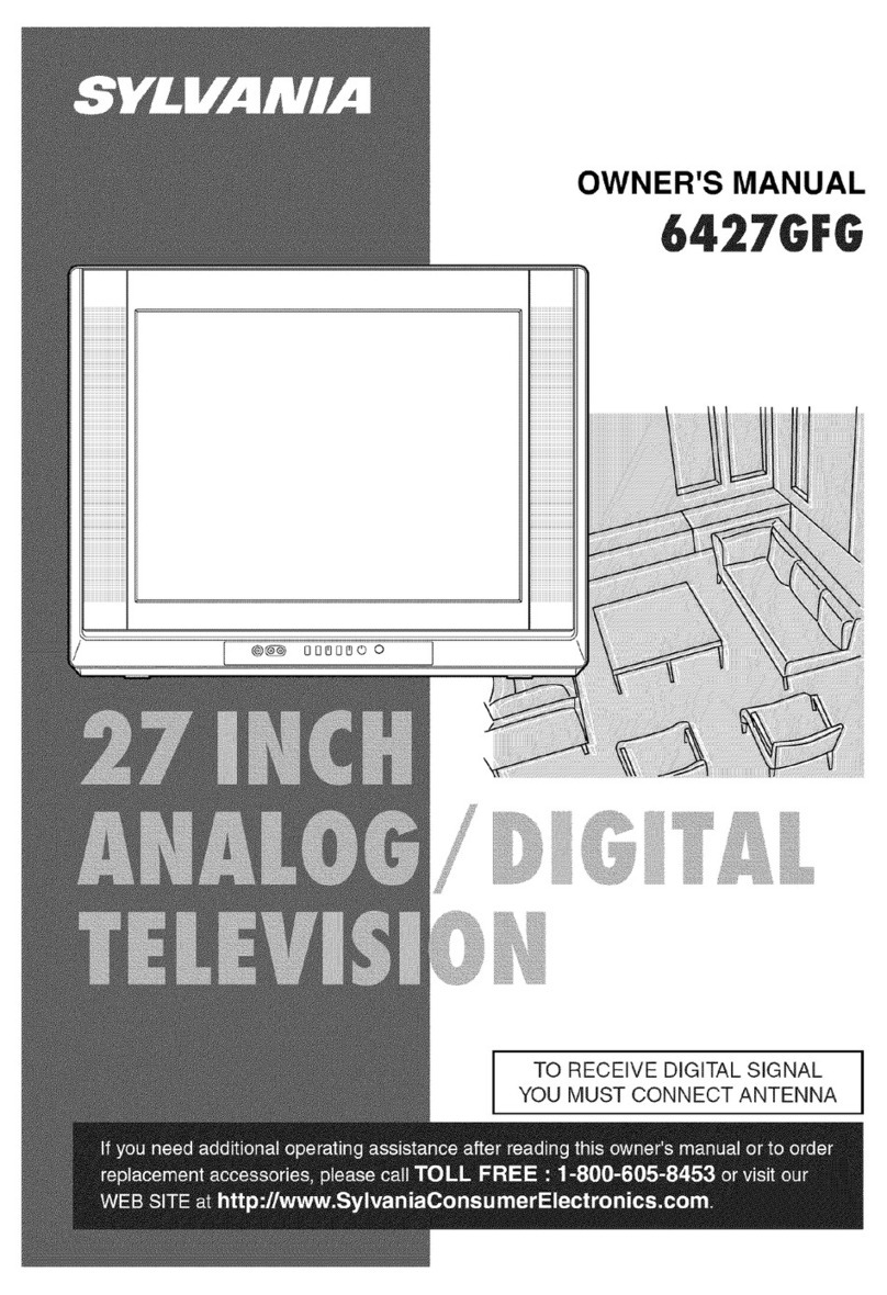
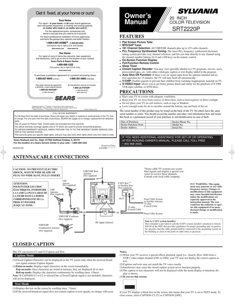
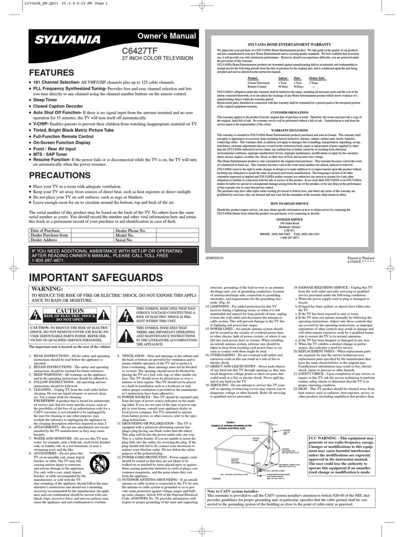
  9. Sylvania 6720FDD User manual

Sylvania 6720FDD User manual

SERVICEMANUAL
Sec. 1: Main Section
ISpecifications
IPreparation for Servicing
IAdjustment Procedures
ISchematic Diagrams
ICBA’s
Sec. 2: Deck Mechanism Section
IStandard Maintenance
IAlignment for Mechanism
IDisassembly/Assembly of Mechanism
Sec. 3: Exploded views
and Parts List Section
IExploded views
IParts List
20" COLOR TV/DVD/VCR
6720FDD
1-8-1 TD900EA
ELECTRICAL ADJUSTMENT INSTRUCTIONS
General Note:
"CBA" is abbreviation for "Circuit Board
Assembly."
NOTE:
Electrical adjustments are required after replacing
circuit components and certain mechanical parts.
It is important to perform these adjustments only
after all repairs and replacements have been com-
pleted.
Also, do not attempt these adjustments unless the
proper equipment is available.
Test Equipment Required
1. NTSC Pattern Generator (Color Bar W/White Win-
dow, Red Color, Dot Pattern, Gray Scale, Mono-
scope, Multi-Burst)
2. AC Milli Voltmeter (RMS)
3. Alignment Tape (FL8A, FL8N), Blank Tape
4. DC Voltmeter
5. Oscilloscope: Dual-trace with 10:1 probe,
V-Range: 0.001~50V/Div,
F-Range: DC~AC-60MHz
6. Frequency Counter
7. Plastic Tip Driver
How to make service remote control
unit:
1. Prepare normal remote control unit (Part No.
NE200UD). Remove 4 screws from the back lid
(Fig. 1-1).
2. Cut off pin 10 of the remote control microprocessor
and short circuit pins 10 and 17 of the microproces-
sor with a jumper wire
How to Set up the Service mode:
Service Mode:
1. Use the service remote control unit.
2. Turn the power on. (Use main power on the TV
unit.)
3. To enter the TV mode, press CH UP or CH DOWN
button on the TV unit.
4. Press "DISC MENU" button on the service remote
control unit. (Version of micro computer will display
on the CRT. (Ex: 057-001)
X-Ray Protection Test
X-Ray protection test should be done when replacing
any parts of this chassis.
1. Short test points J520 and J522 (on H.V. CBA).
2. Confirm that the main power turns off.
3. If the main power does not turn off, then replace
the following parts (D591, Q591, R592, R593,
R594 and IC1201).
4. Perform steps 1 to 3 again.
1. DC 114V (+B) Adjustment
Purpose: To obtain correct operation.
Symptom of Misadjustment: The picture is dark and
unit does not operate correctly.
Note: J521(+B), J535(GND) --- H.V. CBA,
VR2601 --- Power Supply/AV CBA
1. Connect the unit to AC Power Outlet.
2. Connect DC Volt Meter to J521(+B) and
J535(GND).
3. Adjust VR2601 so that the voltage of J521(+B)
becomes +114±0.5V DC.
SCREW
Fig. 1-1
Remote control unit (Bottom)
Test point Adj. Point Mode Input
J521
(+B)
J535
(GND) VR2601 --- -----
Tape M. EQ. Spec.
--- DC Voltmeter +114±0.5V DC
1-8-2 TD900EA
2. H Adjustment
Purpose: To get correct horizontal position and size of
screen image.
Symptom of Misadjustment: Horizontal position and
size of screen image may not be properly displayed.
Note: R583 --- H.V. CBA
1. Connect Frequency Counter to R583.
2. Operate the unit for at least 20 minutes.
3. Enter the Service mode. (See page 1-8-1.) Press
"2" button on the remote control unit and select H-
ADJ Mode.
4. Press CH o/ pbuttons on the remote control unit
so that the display will change "0" to "7."
5. At this moment, choose display "0" to "7" when the
Frequency counter display is closest to
15.734kHz±300Hz.
6. Turn the power off and on again.
3. C-Trap Adjustment
Purpose: To get minimum leakage of the color signal
carrier.
Symptom of Misadjustment: If C-Trap Adjustment is
incorrect, stripes will appear on the screen.
Note: D1304 (Cathode) (B-Out)--- Main CBA
1. Connect Oscilloscope to D1304 (Cathode).
2. Input a color bar signal from RF input.
Enter the Service mode. (See page 1-8-1.)
3. Press "0" button on the remote control unit and
select C-TRAP Mode.
4. Press CH o/ pbuttons on the remote control unit
so that the carrier leakage B-Out (3.58MHz) value
becomes minimum on the oscilloscope.
5. Turn the power off and on again.
Test point Adj. Point Mode Input
R583 CH o/ p
buttons Video ---
Tape M. EQ. Spec.
--- Frequency Counter 15.734kHz±300Hz
Test point Adj. Point Mode Input
D1304
(Cathode)
(B-OUT) CH o/ p
buttons --- Color Bar
Tape M. EQ. Spec.
--- Oscilloscope
Pattern Generator ---
Figure
minimum
Fig. 2
1-8-3 TD900EA
4. V. Size Adjustment
Purpose: To obtain correct vertical height of screen
image.
Symptom of Misadjustment: If V. Size is incorrect,
vertical height of image on the screen may not be
properly displayed.
1. Enter the Service mode. (See page 1-8-1.)
Press "9" button on the remote control unit and
select V-S Mode. (Press "9" button then display will
change to V-P and V-S).
2. Input monoscope pattern.
3. Press CH o/ pbuttons on the remote control unit
so that the monoscope pattern is 90±5% of display
size and the circle is round.
5. V. Shift Adjustment
Purpose: To obtain correct vertical position of screen
image.
Symptom of Misadjustment: If V. position is incor-
rect, vertical position of image on the screen may not
be properly displayed.
1. Enter the Service mode. (See page 1-8-1.)
Press "9" button on the remote control unit and
select V-P Mode. (Press "9" button then display will
change to V-P and V-S).
2. Input monoscope pattern.
3. Press CH o/ pbuttons on the remote control unit
so that the top and bottom of the monoscope pat-
tern are equal to each other.
6. H. Shift Adjustment
Purpose: To obtain correct horizontal position and
size of screen image.
Symptom of Misadjustment: Horizontal position and
size of screen image may not be properly displayed.
1. Enter the Service mode. (See page 1-8-1.)
Press "8" button on the remote control unit and
select H-P Mode.
2. Input monoscope pattern.
3. Press CH o/ pbuttons on the remote control unit
so that the left and right side of the monoscope pat-
tern are equal to each other.
4. Turn the power off and on again.
7. Cut-off Adjustment
Purpose: To adjust the beam current of R, G, B, and
screen voltage.
Symptom of Misadjustment: White color may be
reddish, greenish or bluish.
Test point Adj. Point Mode Input
--- CH o/ p
buttons --- Monoscope
Tape M. EQ. Spec.
--- Pattern Generator 90±5%
Test point Adj. Point Mode Input
--- CH o/ p
buttons --- Monoscope
Tape M. EQ. Spec.
--- Pattern Generator ---
Test point Adj. Point Mode Input
--- CH o/ p
buttons --- Monoscope
Tape M. EQ. Spec.
--- Pattern Generator ---
Test point Adj. Point Mode Input
--- Screen-Control Ext. Black
Raster /
White
Raster
Tape M. EQ. Spec.
--- Pattern Generator See Reference
Notes below
Figure
P
ATTERN GENERATOR
RF INPUT
Fig. 3
1-8-4 TD900EA
Notes: Screen Control FBT --- H.V. CBA
FBT= Fly Back Transformer
Use the Remote Control Unit
1. Degauss the CRT and allow CRT to operate for 20
minutes before starting the alignment.
2. Input the Black raster signal from EXT. input.
3. Enter the Service mode. (See page 1-8-1.)
4. Press the "VOL p" button.
(Press "VOL p" then display will change CUT OFF/
DRIVE, 7Fh adjustment and DVD-KEY).
5. Choose CUT OFF/DRIVE mode then press "1" but-
ton. This adjustment mode is CUT OFF (R).
6. Increase the screen control so that the horizontal
line just appears on the CRT.
7. Press the "CH o/ p" button until the horizontal line
becomes white.
8. Choose CUT OFF/DRIVE mode then press "2" but-
ton. This adjustment mode is CUT OFF (G). Press
"CH o/ p" until the horizontal line becomes white.
9. Choose CUT OFF/DRIVE mode then press "3" but-
ton. This adjustment mode is CUT OFF (B). Press
"CH o/ p" until the horizontal line becomes white.
10.Choose CUT OFF/DRIVE mode then press "4" but-
ton.
11.Input the White Raster Signal from Video In.
12.Adjust the RED DRIVE as needed with the CH o/
pbuttons to get the following value, X= 286, Y=
294.
13.Choose CUT OFF/DRIVE mode then press "5."
Adjust the BLUE DRIVE as needed with the CH o/
pbuttons to get the following value, X= 286, Y=
294.
14.Turn the power off and on again.
8. Sub-Brightness Adjustment
Purpose: To get proper brightness.
Symptom of Misadjustment: If Sub-Brightness is
incorrect, proper brightness cannot be obtained by
adjusting the Brightness Control.
Note: SMPTE Setup level --- 7.5 IRE
1. Enter the Service Mode. (See page 1-8-1.)
Then input SMPTE signal from RF input.
2. Press PICTURE button. (Press PICTURE button
then display will change BRT, CNT, COL, TNT, and
V-T). Select BRT and press CH o/ pbuttons so
that the bar is just visible (See above figure).
3. Turn the power off and on again.
Test point Adj. Point Mode Input
--- CH o/ p
buttons --- SMPTE
7.5IRE
Tape M. EQ. Spec.
--- Pattern
Generator See below
Figure
Black
W
hite
This b
ar
just
visible
Fig. 4
1-8-5 TD900EA
9. Focus Adjustment
Purpose: Set the optimum Focus.
Symptom of Misadjustment: If Focus Adjustment is
incorrect, blurred images are shown on the display.
Note: Focus VR (FBT) --- H.V. CBA
FBT= Fly Back Transformer
1. Operate the unit more than 30 minutes.
2. Face the unit to the East and degauss the CRT
using a Degaussing Coil.
3. Input the monoscope pattern.
4. Adjust the Focus Control on the FBT to obtain clear
picture.
10. SIF Adjustment
Purpose: To set the SIF (Sound Intermediate Fre-
quency).
Symptom of Misadjustment: Audio may not sound
correctly.
Note: This adjustment automatically done by the
chrominance IC (IC1301).
11. CCS Text Box Location
Note: This adjustment automatically done by the
microcomputer.
12. Head Switching Position Adjustment
Purpose: Determine the Head Switching Point during
Playback.
Symptom of Misadjustment: May cause Head
Switching Noise or Vertical Jitter in the picture.
Note: Unit reads Head Switching Position automati-
cally and displays it on the screen (Upper Left Corner).
1. Playback test tape (FL8A, FL8N).
2. Enter the Service Mode. (See page 1-8-1.)
Then press the number 5 button on the remote
control unit.
3. The Head Switching position will display on the
screen; if adjustment is necessary follow step 4.
6.5H(412.7µs) is preferable.
4. Press "CH o" or "CH p" button on the remote con-
trol unit if necessary. The value will be changed in
0.5H steps up or down. Adjustable range is up to
9.5H. If the value is beyond adjustable range, the
display will change as:
Lower out of range: 0.0H
Upper out of range: -.-H
5. Turn the power off and on again.
The following 2 adjustments normally are not
attempted in the field. They should be done
only when replacing the CRT then adjust as a
preparation.
13. Purity Adjustment
Purpose: To obtain pure color.
Symptom of Misadjustment: If Color Purity Adjust-
ment is incorrect, large areas of color may not be
properly displayed.
1. Set the unit facing east.
2. Operate the unit for over 30 minutes before adjust-
ing.
3. Fully degauss the unit using an external degauss-
ing coil.
4. Set the unit to the AUX Mode which is located
before CH2 then input a red raster from video in.
5. Loosen the screw on the Deflection Yoke Clamper
and pull the Deflection Yoke back away from the
screen. (See Fig. 6.)
6. Loosen the Ring Lock and adjust the Purity Mag-
nets so that a red field is obtained at the center of
the screen. Tighten Ring Lock. (See Fig. 5,6.)
7. Slowly push the Deflection Yoke toward the bell of
the CRT and set it where a uniform red field is
obtained.
8. Tighten the clamp screw on the Deflection Yoke.
Test point Adj. Point Mode Input
--- Focus Control --- Monoscope
Tape M. EQ. Spec.
--- Pattern Generator See below.
Test point Adj. Point Mode Input
--- Deflection Yoke
Purity Magnet --- Red Color
Tape M. EQ. Spec.
--- Pattern Generator See below.
Figure
BLUE
GREEN RED
Fig. 5
1-8-6 TD900EA
14. Convergence Adjustment
Purpose: To obtain proper convergence of red, green
and blue beams.
Symptom of Misadjustment: If Convergence Adjust-
ment is incorrect, the edge of white letters may have
color edges.
1. Set the unit to the AUX Mode which is located
before CH2, then input a Dot or crosshatch pattern.
2. Loosen the Ring Lock and align red with blue dots
or Crosshatch at the center of the screen by rotat-
ing (RB) C.P. Magnets. (See Fig. 7.)
3. Align red / blue with green dots at the center of the
screen by rotating (RB-G) C.P. Magnet.
(See Fig. 8.)
4. Fix the C.P. Magnets by tightening the Ring Lock.
5. Remove the DY Wedges and slightly tilt the Deflec-
tion Yoke horizontally and vertically to obtain the
best overall convergence.
6. Fix the Deflection Yoke by carefully inserting the
DY Wedges between CRT and Deflection Yoke.
Test point Adj. Point Mode Input
--- C.P. Magnet (RB),
C.P. Magnet (RB-G),
Deflection Yoke --- Dot Pattern
or
Crosshatch
Tape M. EQ. Spec.
--- Pattern Generator See below.
Figure
DY WEDGE
DEFLECTION YOKE
C.P. MAGNET
RING LOCK
SCREW
SCREW
RB-G
RB
PURITY
CRT COIL
COIL CLAMPER
C.P. MAGNET
CLAMPER
Fig.
6
Fig.
7
Fig.
8
B
G
RR
G
B
C.P. MAGNET (RB)
RB
G
RB
G
C.P. MAGNET (RB-G)
1-9-1 TD945TEST
FIRMWARE RENEWAL MODE
1. Turn the power on and remove the disc on the tray.
2. To put the DVD player into version up mode, press
[9], [8], [7], [6], and [SEARCH MODE] buttons on
the remote control unit in that order. The tray will
open automatically.
Fig. a appears on the screen.
The DVD player can also enter the version up
mode with the tray open. In this case, Fig. a will be
shown on the screen while the tray is open.
3. Load the disc for version up.
4. The DVD player enters the F/W version up mode
automatically. Fig. b appears on the screen.
The appearance shown in (*2) of Fig. b is
described as follows:
5. After programming is finished, the tray opens auto-
matically. Fig. c appears on the screen.
At this time, no buttons are available.
6. Unplug the AC cord from the AC outlet. Then plug it
again.
7. Turn the power on by pressing the power button
and the tray will close.
8. Press [1], [2], [3], [4], and [DISPLAY] buttons on the
remote control unit in that order.
Fig. d appears on the screen.
9. Press [3] button on the remote control unit.
Fig. e appears on the screen.
10.To finish this mode, press [POWER] button.
F/W Version Up Mode
Please insert a DISC
for F/W Version Up.
EXIT: SELECT
Fig. a Version Up Mode Screen
Fig. b Programming Mode Screen
F/W Version Up Mode
VERSION : ********
Reading...(*2)
EXIT: SELECT
AppearanceNo. State
Reading... Sending files into the memory
Erasing... Erasing previous version data
Programming...
1
2
3 Writing new version data
Fig. c Completed Program Mode Screen
F/W Version Up Mode
VERSION : ********
Completed
SUM : 7abc (*3)
Fig. d
model: ****** Ver: **** Region: **
1: VFD TEST
2: TT REPEAT PLAY
3: EEPROM CLEAR
4: MEASUREMENT SERVO
5: DISC READ CHECK
6: MECHA CHECK
7: DISC INFO
8: ERROR RATE
EXIT: SELECTRETURN: -----
Fig. e
model: ****** Ver: **** Region: **
TEST 3: EEPROM CLEAR
EEPROM CLEAR: OK
EXIT: SELECTRETURN: -----
CONTROL
HEAD
CL1402
AC HEAD ASSEMBLY
MAIN CBA
POWER SUPPLY /AV CBA
RF-SW
T-REEL
DV-SYNC
C-SYNC C-SYNC
V-ENV
CTL(+)
D1224 S-LED
D1204 REC
D1216 DVD
D1217
TV/VCR
Q1210
Q1211
Q1207
P-ON+5V
REC-LED
KEY0
RS1201
REMOTE
SENSOR
KEY1
DVD-H
TV/VCR-LED
RESET
ROTA
D-REC-H D-REC-H
REC-SAFETY
A-MUTE
SCL
REMOTE
SDA
A-MUTE
CTL(-)
RF-SW
DV-SYNC
V-ENV
ROTA
IC1201
(SERVO/SYSTEM CONTROL)
AL+5V
AL+5V
94
95
80
34
18
15
10
13
74
33
8
44
65
72
CTL-AMP-OUT
DVD-REMOTE
97
CTL-AMP-OUT
TP1201
(DECK ASSEMBLY)
Servo/System Control Block Diagram
BLOCK DIAGRAMS <TV/VCR Section>
T-REEL
Q1206
Q1205
RESET
TIMER+5V
ST/SAP-MODE
4NORMAL-H
22
28
EXT-H 29
RENTAL 30
SPL-PLAY
SP/LP/SLP
EXT-H
RENTAL
SPL-PLAY
32
REC/EE/PB REC/EE/PB
27
VOL-CONT VOL-CONT
11 EXT-H
A-MUTE
JACK-MUTE JACK-MUTE
DVD-MAIN-POWER
67
SW1211
REC
SAFETY
FROM/TO
VIDEO BLOCK
FROM/TO
AUDIO BLOCK
FROM/TO
Hi-Fi AUDIO
BLOCK
1-10-1 1-10-2 TD900BLS
SCL
(MEMORY)
SDA
6
5
P-DOWN 84
P-ON-H P-DOWN
P-ON-H
31
LD-SW1
I2C-OPEN 45
71
AL+5V
SW1212
LD-SW
CS
7
FROM/TO
POWER
SUPPLY BLOCK
SDA
SCL FROM/TO
CHROMA
BLOCK
IC1202
WF3
ENV-DET 17
V-H-SW ENV-DET
V-H-SW
16
SDA
SCL
Hi-Fi-H-SW
ST/SAP-IN
NORMAL-H
DVD-MAIN-POWER
Hi-Fi-H-SW
19
26
48
21
DVD-H
DVD-A-MUTE
42
5
KEY SWITCH
SW1201 SW1203,
SW1206 SW1210
5 5KEY1
CN2805
CN2803
CN1805
KEY SWITCH
SW2401 SW2408
14
25
12SDATA
1220 SDATA
FROM/TO
DVD SYSTEM
CONTROL/SERVO
BLOCK
<DVD SECTION>
CN401
CN2402
6
CN1804
13SCLK
14CS
15
DVD-REMOTE
M
1P-ON+12V(2)
5C-CONT
6
FG-GND
7LD-CONT
CAPSTAN
MOTOR
CAPSTAN MOTOR
P-ON+5V
D/L+15V
P-ON+12V
10M-GND
11D/L+12V
9D-PFG
12D/L+15V
END-SENS.
Q201
SENSOR CBA
(END-SENSOR)
ST-SENS.
Q202
SENSOR CBA
(ST-SENSOR)
21 SCLK
18 CS
22
DVD-REMOTE
52
51
50
SDATA
SCLK
CS
69
DVD-A-MUTE
5CTL(+)
6CTL(-)
8D-CONT
4
C-F/R
3C-FG
2P-ON+5V(3)
66
87
76
82
77
90
C-F/R
C-FG
C-CONT
LD-CONT
D-CONT
D-PFG
CL1201
M
LOADING
MOTOR
CYLINDER ASSEMBLY
M
DRUM
MOTOR
PG
SENSOR
9
7
ST-SENS.
END-SENS.
13
14
15
AFT
AFT
D-REC-H
SP/LP/SLP
FUNCTION CBA
Q2621
Q2622
Q2623
Video Block Diagram
1-10-3 1-10-4 TD900BLV
REC VIDEO SIGNAL PB VIDEO SIGNAL MODE: SP/REC
LUMINANCE
SIGNAL PROCESS
MAIN CBA
CL1401
Q1401
TP1402
V-OUT
V-AGC
R P
FBC
Y/C
MIX
CCD 1H
DELAY
R
P
DOC YNR Y/C COMB
CHROMINANCE
SIGNAL PROCESS
IC1401
VIDEO/AUDIO
SIGNAL PROCESS 35
42
38
17
CHARA
MIX
6dB
AMP
VXO
ENV
DET
AGC
AMP
HPF
FROM
SERVO/SYSTEM
CONTROL BLOCK
RF-SW
TP1401
WF1
TP1403
HA-MONITOR
BUFFER
DV-SYNC
SP/LP/SLP
ROTA
DV-SYNC
ROTA
14
36
16
71
39
59
73
SPL-PLAY
REC/EE/PB
RENTAL
SPL-PLAY
REC/EE/PB
RENTAL
42
EXT-H
74
45 47 49 44
Q1402
WF6
WF5
WF4
WF2
L
R
VIDEO (R)-1 HEAD
VIDEO (L)-1 HEAD
(DECK ASSEMBLY)
V(R)-1
V-COM
V(L)-1
9
8
7
V(L)-2
V-COM
V(R)-2
6
5
4
13
88
89
90
91
FROM/TO
SERVO/SYSTEM
CONTROL BLOCK
CYLINDER ASSEMBLY
R
L
RF-SW
93
V-ENV
V-H-SW
ENV-DET ENV-DET
VIDEO (L)-2 HEAD
VIDEO (R)-2 HEAD
15
94
82
83
84
85
SP
EP
TO
CHROMA
BLOCK
62 61
X1401
3.58MHz
VIDEO
V-OUT
TV-
EXT-V-IN
VIDEO
TU1001
(TUNER UNIT)
JK1701
VIDEO-IN
SP/LP/SLP
BUFFER
Audio Block Diagram
BLOCK DIAGRAM FOR SECTION 2 (DECK MECHANISM)
MAIN CBA
POWER SUPPLY / AV CBA
PB-AUDIO SIGNAL DVD AUDIO SIGNAL
REC-AUDIO SIGNAL
1-10-5
IC1401
TD900BLA1-10-6
BIAS
OSC
Q1872
P-ON+5V
P-ON+5V
Q1871
Q1873
Q1874
Q1875
(AUDIO SIGNAL PROCESS)
N-A-IN
N-A-OUT TP1802
NA-IN-YCA
AUDIO
HEAD
AC HEAD ASSEMBLY
A-COM
A-PB/REC
CL1402
CN1804CN2803
AUDIO
ERASE
HEAD
AE-H
AE-H/FE-H
1
2
FE-H
FE-H-GND
FULL
ERASE
HEAD
CL1403
4
3
1
2
FE HEAD UNIT
REC
AMP
798
6
AUTO
BIAS
99
LINE
AMP MUTE 96
P
R
ALC
7112
D-REC-H
D-REC-H
EXT-H
A-MUTE
EXT-H FROM SERVO/SYSTEM
CONTROL BLOCK
4
78
11
WF7
WF8
FROM/TO SERVO/SYSTEM
CONTROL BLOCK
3
1
EQ
AMP
100
SP/LP-ON
2
IC1802
(OUTPUT SELECT)
IC2201
(OP AMP)
JK1801
HEADPHONE
JACK
SPEAKER
R-CH
CN1802
CN1805
SP1802
FROM/TO
Hi-Fi AUDIO
BLOCK
FROM DVD
AUDIO BLOCK
<DVD SECITON>
CN601
FROM
Hi-Fi AUDIO
BLOCK
SW CTL.
Q2204 Q1803
CN2401
Q2202
JK2201
DIGITAL
A-OUT
(COXIAL)
A-OUT(L)
A-OUT(R)
A-OUT(R)
A-OUT(L)
2
1
12
13 14
15
1110
6
2 1
7
Q2205
BUFFER
IC1801
(AUDIO AMP)
DC VOL.
5
2 12
7
6
Q2207
76
80
7
DVD-A-MUTE
1 SPDIF
4 DVD-A(R)
6 DVD-A(L)
8 8DVD-A(R)
7 7DVD-A(L)
11 11JACK-MUTE
10 10
DVD-A-MUTE
5 5
JACK-OUT(R)
4 4
JACK-OUT(L)
FUNCTION CBA
SPEAKER
L-CH
CN2801CN2805
SP2801
SP-R 1
SP-GND 2
SP-L 1
SP-GND 2
2 2SP-L
DVD-A-MUTE
CL1802
CL2801
FROM SERVO/SYSTEM
CONTROL BLOCK
VOL-CONT
Q1212
DVD-H
JACK-MUTE
AL+5V
WF19
WF20
DATA(AUDIO) SIGNAL
57
7
48 47
13 14
69
6
7
R-CH
INSEL
L-CH
INSEL
NOR
SW
SERIAL
DATA
DECODER
OUTPUT
SELECT
VCO LPF
L-CH BPF
R-CH
PNR
PILOT
DET
CONT
STEREO
PLL
STEREO
FILTER
SAP
FILTER
SAP
DET
SIF
DEMOD
SAP
DEMOD L-R
DEMOD
ST/SAP
SW MATRIX
L-CH
PNR
LIM DEV
COMP
SW
NOISE
VCO LPF
LIM DEV
COMP
COMP
DC
SW
NOISE
dBX
DEC
ENV
DET
MODE
OUT
RIPPLE
FILTER
DO
DET
MATRIX
R-CH BPF
P
R
R
L
P
R
HOLD
PULSE
NOISE
DET
34 33
23
4
80
78
37
38
54
77
1
39
26
24
27
N-A-OUT
LIM
49
A-OUT (L)
A-OUT (R)
N-A-IN
Hi-Fi-H-SW
A-MUTE
NORMAL-H
40 ST/SAP-MODE
FROM/TO AUDIO
BLOCK
SCL
P-ON+9V
TO SERVO/SYSTEM
CONTROL BLOCK
Hi-Fi
AUDIO
(R) HEAD
Hi-Fi
AUDIO
(L) HEAD
CYLINDER
ASSEMBLY
MAIN CBA
Hi-Fi-A(R) 3
Hi-Fi-COM 2
Hi-Fi-A(L) 1
CL1401
IC1751(MTS/ SAP/ Hi-Fi AUDIO PROCESS/ Hi-Fi HEAD AMP)
Hi-Fi Audio Block Diagram
TD900BLH1-10-7 1-10-8
REC-AUDIO SIGNALPB-AUDIO SIGNAL
PILOT
CANCEL
TO
AUDIO BLOCK
FROM/TO
SERVO/ SYSTEM
CONTROL BLOCK
FROM
SERVO/SYSTEM
CONTROL BLOCK
62 63
JK1702
AUDIO-IN(L)
JK1703
AUDIO-IN(R)
BUFFER
Q1010
SIF
TU1001
(TUNER UNIT)
Q1701
TP1701 TP1702
SDA
Hi-Fi-L Hi-Fi-R
TD900BLC
X1301
3.58MHz
CN1301
IC1301
(CHROMA/DEFLECTION SIGNAL PROCESS)
SDA
SCL
FSC
10
9
13
16
IC1201 (OSD)
V-SYNC
H-SYNC
OSD-R
OSD-G
OSD-B
59
58
60
62
63
64
OSD-BLK
EXT-V-IN
FROM
VIDEO BLOCK
V-OUT
FROM/TO
CRT/H.V. BLOCK
CN503
12
GREEN11
BLUE
FBP3
H-DRIVE4
ACL/ABL
V-DRIVE8
V-RAMP-FB
Chroma Block Diagram
SDA
AFT
SCL
FROM/TO
SERVO/
SYSTEM
CONTROL
BLOCK
REC VIDEO SIGNAL PB VIDEO SIGNAL DVD VIDEO SIGNAL
WF16
WF15 WF9
56
CV-IN
10
18
28
29
34
35
8
9
31
13
10
11
12
15
14
4
5
3
2
40
41
16
6
20
25
23
CHROMA
TRAP
SERIAL
I/F
INTELLIGENT
MONITORING
CHROMA
BPF
SYNC
SEPARATION
LUMA
SIGNAL
PROCESS
CIRCUIT
CHROMA
SIGNAL
PROCESS
CIRCUIT
H-SYNC
PROCESS
CIRCUIT
V-SYNC
PROCESS
CIRCUIT
OSD MIX/RBG MATRIX/
BLIGHT/DRIVE AMP/
HV BLANKING
TUNER
TUNER
FILTER
TUNING VXCO
C-SYNC
LINE
VCR
VCR
LINE
RED
AFT
TU1001
(TUNER UNIT)
1-10-9
SWCTL
IC1802
(OUTPUT SELECT)
Q1806
D-REC-H
S-C
S-Y
DVD-Y12
DVD-C10
BUFFER
BUFFER
CN1803 CN2804 Q2210
Q2211
CN2401
DVD-C
TP2204
DVD-Y
TP2203
POWER SUPPLY/AV CBA
TV-VIDEO
7
5
FROM DIGITAL
SIGNAL PROCESS
BLOCK
<DVD SECTION>
CN601
1-10-10
5
3
9
4
VCR
DVD
MAIN CBA
WF17
WF18
+5.7V
REG. 27 +5V CTRL TO POWER
SUPPLY BLOCK
30
+8V
14 14DVD-Y
15 15DVD-C
TD900BLCRT
CRT/H.V. Block Diagram
1-10-121-10-11
PULSE
UP
AMP
THERMAL
PROTECTION
3
6
7
15
V-DRIVE
8
H-DRIVE
4
8
10
7
9
6
GREEN AMP
BLUE AMP
Q503,Q506
Q502,Q505
Q501,Q504
H.DRIVE
Q591
Q571 T572
FBP
ACL/ABL
V-
DRIVE
H-
DRIVE
D.Y.
L551
IC551 (V-DEFLECTION CONTROL)
T571 F.B.T.
ANODE
FOCUS
SCREEN
3
5
CL503A
7
CL504A
R
G
B
HEATER
ANODE
GND
V501
CRT
GND
FOCUS
SCREEN
JK501
HEATER 11
CN501A
CL501CL501A
REC VIDEO SIGNAL PB VIDEO SIGNAL
CN571
+180V 33
11
S
F
HV
FOCUS VR
SCREEN VR
+B7
CL502A
2
3
4 RED
GREEN
BLUE
8+B
5DEF+B
H.OUTPUT
V-RAMP-FB
1
3
5
4
5
4
3
1
WF13WF14
WF12
WF10
WF11
RED AMP
J521
+B
J535
GND
5
CN502 CL502B
CN503 CL503B
CN503 CL504B
3
7
4
8
2
3
4
7
8
5
V-DRIVE
8
H-DRIVE
4
FBP
ACL/ABL
3
5
7
RED
12
GREEN
11
BLUE
10
V-RAMP-FB
5 +B
6 +B
3 DEF+B
DVD VIDEO SIGNAL
JUNCTION-B
CBA
JUNCTION-A
CBA
FROM
POWER
SUPPLY
BLOCK
CN2602
FROM
CHROMA
BLOCK
CN1301
FROM/TO
CHROMA
BLOCK
CN1301
CRT CBA
H.V. CBA
Power Supply Block Diagram
LINE
FILTER
BRIDGE
RECTIFIER
T2601
IC2601
ERROR
VOLTAGE DET
W2601 F2601
4A/125V L2601 D2603 D2606
TD900BLP
DEGAUSSING
COIL
CN2601
PS2601
HOT COLD
1-10-141-10-13
POWER SUPPLY/AV CBA
MAIN CBA
DVD MAIN CBA UNIT
NOTE :
The voltage for parts in hot circuit is measured using
hot GND as a common terminal.
CAUTION !
Fixed voltage power supply circuit is used in this unit.
If Main Fuse (F2601) is blown, check to see that all components in the power supply
circuit are not defective before you connect the AC plug to the AC power supply.
Otherwise it may cause some components in the power supply circuit to fail.
4A 125V
SWITCHING
Q2601
IC1602
P-DOWN
(TO PIN84 OF IC1201)
Q2604
IC2603
IC2604
VR2601
Q2602
+5V REG.
+B ADJ
5 +B
6 +B
3 DEF+B
Q1608
SW+5V
Q1611
SW+5V
Q1613
SW+5V
P-ON+5V
P-ON+5V
P-ON+5V
T+5V
P-ON+9V
P-ON+12V
AL+5V
P-ON+12V
Q1612
AL+33V
D/L+15V
P-ON+5V
+5V-CTRL
P-ON-H
(FROM PIN31 OF IC1201)
DVD-MAIN-POWER
(FROM PIN42 OF IC1201)
CN2602 TO CN502
TO
CRT/H.V.
BLOCK
CN2804 CN1803
CN2803 CN1804
CN2402 CN401
DVD-ON+3.3V
1
23
4
13 13DVD-ON+5V
16 16
DVD-MAIN-POWER
9 9P-ON-H
2 2P-ON+9V(3)
19 19AC-DOWN
19 19D/L+15V
4 4P-ON+9V(1)
10 10P-ON+12V(1)
18 18P-ON+12V
9 9AL+33V
8 8AL+5.7V
6 6P-ON+9V(2)
3 3EV+1.5V
2 2EV+1.5V
1 1EV+1.5V
4 4EV+3.3V
5 5EV+3.3V
17 17DVD-ON+3.3V
14 14AL+9V
15 15AL+9V
19 19PWRCON
DVD-ON+5V
EV+3.3V
EV+1.5V
AL+9V
12
16
15
14
11
13
10
9
2
3
5
7
FEED
BACK
+3.3V
REG.
REG.
Q2606
Q2614
Q2607
Q2613
Q2609
Q2605
Q2615
Q2617
1 2
4
IC2602
+1.5V
REG.
1 2
4
Q2611
Q2610
Q2612
Q2608
FOR CONTINUED PROTECTION AGAINST RISK OF FIRE,
REPLACE ONLY WITH SAME TYPE 4 A, 125V FUSE.
CAUTION:
ATTENTION: UTILISER UN FUSIBLE DE RECHANGE DE MÊME TYPE DE 4A, 125V.
4A 125V
FROM CHROMA
BLOCK
P-ON+9V
PWRCON
FROM DVD SYSTEM
CONTROL
/SERVO BLOCK
<DVD SECTION>
DVD System Control/Servo Block Diagram
TD900BLDS
27
7
8
3
15
10
14
26
1
2
3
4
6
23
5
17
18
12
11
14
13
15
16 25
24
54CS
55
SDATA
61
REMOTE
PWRCON PWRCON
53
SCLK
CN401
DVD MAIN CBA UNIT
DRIVE CBA
IC301
(SERVO DRIVE)
IC451
(CLOCK GENERATOR)
BLOCK DIAGRAMS < DVD Section >
IC202
(OP AMP)
12 14
CN301
FG CBA
FG
SENSOR
M
SLED
MOTOR
M
SPINDLE
MOTOR
IC101
(MICRO CONTROLLER)
+
-+
-
+
-
+
-
+
-
+
-
+
-
SLED
MOTOR
DRIVE
FOCUS
ACTUATOR
DRIVE
1/4
1/4 PLL2
X451
MULTI
PLL X'TAL
OSC 36.864MHz
OSC
SPINDLE
MOTOR
DRIVE
TRACKING
ACTUATOR
DRIVE
EXT CLOCK
CLK33M
BE CLOCK
172
170
150
TRAY-OUT
TRAY-IN
FG-IN
97
SLD70
SPDL71
TRACKING
DRIVE
152
FOCUS DRIVE
60
66
TO DIGITAL SIGNAL
PROCESS BLOCK
FS(+)
FS(-)
TS(+)
TS(-)
TO DVD/ AUDIO
BLOCK 51
ADAC-MD
50 ADAC-MC
96 ADAC-ML
ADAC-MC
ADAC-ML
PCM-SCLK
95
A-MUTE
ADAC-MD
A-MUTE
17
92
FSEL
RESET68
RESET
IC461
5 4
+3.3V
TRAY-OUT
TRAY-IN
FOCUS SERVO SIGNAL TRACKING SERVO SIGNAL SLED SERVO SIGNAL SPINDLE SERVO SIGNAL
3SP(+)
4SP(-)
5TRAY-OUT
6TRAY-IN
7GND
8SL(-)
9SL(+)
1FG-IN
18 CS
20 SDATA
21 SCLK
22
DVD-REMOTE
FROM/TO SERVO
/SYSTEM CONTROL
BLOCK
<TV/VCR SECTION>
CN2402
63 TO POWER
SUPPLY BLOCK
<TV/VCR SECTION>
1-10-161-10-15
DVD-
Digital Signal Process Block Diagram
TD900BLD
C 6
D 7
A 8
B 5
F 10
E 2
DVD-LD 14
CD-LD 12
PD-MONI 13
FS(+) 18
FS(-) 19
TS(+) 20
TS(-) 17
CN201
CN201
CN201
IC201
(SW)
IC105 (LATCH)
IC102 (SDRAM) IC101 (MICRO CONTROLLER)
FS
FS(+)
CD/DVD
FS(-)
TS(+)
TS(-)
TS
PICK-UP
UNIT
DETECTOR
CD/DVD 9
Q251,Q252
CD DVD
AMP
Q253,Q254
AMP
4
1 3
6
GND(DVD-PD)
15
GND(CD-PD)
16
GND(LD)
11
FROM DVD SYSTEM
CONTROL/SERVO
BLOCK
RF
SIGNAL
PROCESS
CIRCUIT
DVD/CD
FORMATTER
AUDIO
I/F
VIDEO
I/F
NTSC/PAL
ENCODER
DMA
BCU
INST.
ROM 32BIT
CPU
DATA
ROM
INTERRUPT
CONTROLLER
WATCH DOG
TIMER
CPU
I/F
TIMER
DECODER
I/F
CPU
I/F
READ
MEMORY
DATA
ROM
DSP
DECODER
PIXEL
OPERATION
I/O
PROCESSOR
INST.
ROM
DATA
ROM
INST.
ROM
DATA
ROM
INST.
ROM
SERIAL
D/A
GENERAL
I/O
INTERRUPT
CONTROLLER
TIMER
WATCH DOG
TIMER
32BIT CPU
STREAM
I/F
EXTERNAL
MEMORY
I/F
SDRAM
ECC
UMAC
124
125
122
123
128
129
126
127
131
130
135
133
132
134
78
DEBUG
BCU
INST
CACHE
D TYPE
LATCH
DATA
CACHE
D/A
TO CHROMA
BLOCK
CN2401
158
164
YCN601
C
TO DVD
AUDIO
BLOCK
181
SPDIF
175
PCM-BCK
176
PCM-DATA0
174
PCM-LRCLK
EXADT (0-15), EXADR (16-19)
EXADT (0-7)
EXADT (8-15)
EXADR (0-7)
EXADR (0-15)
EXADR (8-15)
SDRAM DATA(0-31)SDRAM DATA(0-31)
SDRAM ADDRESS(0-10)SDRAM ADDRESS(0-10)
2
9
~
12
19
~
210
235
~
IC104 (LATCH)
D TYPE
LATCH
2
9
~
12
19
~
2
13
184
205
247
256
~~~
2
13
31
56
74
85
~~~
IC103 (FLASH ROM)
FLASH
ROM
29
36
38
45
~
~
DVD MAIN CBA UNIT
DATA(VIDEO/AUDIO) SIGNAL DVD VIDEO SIGNAL DATA(AUDIO) SIGNAL FOCUS SERVO SIGNAL TRACKING SERVO SIGNAL
24
27
60
66
~~
EXADT (0-15)
EXADR (16-19)
~
1
9
16
25
48
~
1 DVD-Y
3 DVD-C
1-10-18
1-10-17
<TV/VCR SECTION>
DVD Audio Block Diagram
TD900BLAD
IC601 (AUDIO DAC)
7
8CN601
1
2
3
13
14
15
16
FROM
DVD SYSTEM
CONTROL
/SERVO
BLOCK
FROM
DIGITAL
SIGNAL
PROCESS
BLOCK
SERIAL
PORT
SERIAL
CONTROL
4X/8X
OVERSAMPLING
DIGITAL FILTER
/FUNCTION
CONTROLLER
ENHANCED
MULTI-LEVEL
DELTA-SIGMA
MODULATOR
DAC LPF+AMP L-CH
R-CH
LPF+AMP
DAC
SYSTEM CLOCK
PCM-BCK
SPDIF
PCM-DATA0
PCM-LRCLK
ADAC-MD
ADAC-MC
ADAC-ML
PCM-SCLK
DVD MAIN CBA UNIT
DATA(AUDIO) SIGNAL
A-MUTE
12 SPDIF
7 DVD-A(L)
9 DVD-A(R)
6 DVD-A-MUTE
TO AUDIO BLOCK
<TV/VCR SECTION>
CN2401
DVD AUDIO SIGNAL
1-10-201-10-19
A1
A2
A3
A4
B1
B2
B3
B4
C1
C2
C3
C4
D1
D2
D3
D4
E1
E2
E3
E4
F1
F2
F3
F4
Main 1/5 Schematic Diagram < TV/VCR Section >
1-11-3 1-11-4 TD900SCM1
MAIN 1/5
Ref No. Position
IC1201 C-3
IC1202 D-1
Q1205 A-1
Q1206 D-3
Q1207 A-2
Q1210 A-2
Q1211 A-1
Q1212 D-3
CL1201 F-4
TP1201 B-4
ICS
TRANSISTORS
TEST POINT
CONNECTOR
G1
G2
G3
G4
H1
H2
H3
H4
I1
I2
I3
I4
J1
J2
J4
K1
K2
K3
K4
L1
L2
L3
L4
J3
REC VIDEO SIGNAL
REC AUDIO SIGNAL
PB VIDEO(TV/VCR/LINE) SIGNAL
PB AUDIO (TV/VCR/LINE) SIGNAL
1-11-5 1-11-6 TD900SCM2
Main 2/5 Schematic Diagram < TV/VCR Section >
MAIN 2/5
Ref No. Position
IC1401 H-2
Q1401 K-2
Q1402 K-3
Q1403 K-4
Q1871 G-2
Q1872 H-1
Q1873 G-2
Q1874 G-1
Q1875 G-1
CL1401 G-3
CL1402 L-1
CL1403 L-1
TP1401 I-2
TP1402 K-3
TP1403 I-4
TP1802 G-2
IC
TRANSISTORS
CONNECTORS
TEST POINTS

Other manuals for 6720FDD

1

Other Sylvania TV manuals

Sylvania C6420FF User manual

Sylvania

Sylvania C6420FF User manual

Sylvania CR202SL8 User manual

Sylvania

Sylvania CR202SL8 User manual

Sylvania CD202SL8 User manual

Sylvania

Sylvania CD202SL8 User manual

Sylvania SRT4127W User manual

Sylvania

Sylvania SRT4127W User manual

Sylvania 6427GFG A User manual

Sylvania

Sylvania 6427GFG A User manual

Sylvania SRT2232X User manual

Sylvania

Sylvania SRT2232X User manual

Sylvania 6900DTD User manual

Sylvania

Sylvania 6900DTD User manual

Sylvania W-4913LT User manual

Sylvania

Sylvania W-4913LT User manual

Sylvania SRT2013 User manual

Sylvania

Sylvania SRT2013 User manual

Sylvania 6427CTA User manual

Sylvania

Sylvania 6427CTA User manual

Sylvania Sylvania SRT199V User manual

Sylvania

Sylvania Sylvania SRT199V User manual

Sylvania SRC19ACV User manual

Sylvania

Sylvania SRC19ACV User manual

Sylvania SRC13ADV User manual

Sylvania

Sylvania SRC13ADV User manual

Sylvania 6419TA User manual

Sylvania

Sylvania 6419TA User manual

Sylvania 6413CTA User manual

Sylvania

Sylvania 6413CTA User manual

Sylvania Sylvania W4913TA User manual

Sylvania

Sylvania Sylvania W4913TA User manual

Sylvania 6427GFG A User manual

Sylvania

Sylvania 6427GFG A User manual

Sylvania Sylvania 4919LT User manual

Sylvania

Sylvania Sylvania 4919LT User manual

Sylvania 6424TF User manual

Sylvania

Sylvania 6424TF User manual

Sylvania SRT2220P User manual

Sylvania

Sylvania SRT2220P User manual

Sylvania 6427FF User manual

Sylvania

Sylvania 6427FF User manual

Sylvania Sylvania SRT2019 A User manual

Sylvania

Sylvania Sylvania SRT2019 A User manual

Sylvania SRT2213, SRT2219 User manual

Sylvania

Sylvania SRT2213, SRT2219 User manual

Sylvania SST4324 User manual

Sylvania

Sylvania SST4324 User manual

Popular TV manuals by other brands

Sony BRAVIA KD-55XE70 Series operating instructions

Sony

Sony BRAVIA KD-55XE70 Series operating instructions

Samsung CS-29A10HW Owner's instructions

Samsung

Samsung CS-29A10HW Owner's instructions

RCA 46LA45RQ Dimension Guide

RCA

RCA 46LA45RQ Dimension Guide

Samsung 550 Series user manual

Samsung

Samsung 550 Series user manual

Toshiba 23DL934B owner's manual

Toshiba

Toshiba 23DL934B owner's manual

PRTC Digital TV Guide

PRTC

PRTC Digital TV Guide

Palsonic MODEL 6840PFST owner's manual

Palsonic

Palsonic MODEL 6840PFST owner's manual

JVC AV-14AMG3, AV-14FMG3, AV-20NMG instructions

JVC

JVC AV-14AMG3, AV-14FMG3, AV-20NMG instructions

Blaupunkt 40/234I-GB-5B-FHKUP user guide

Blaupunkt

Blaupunkt 40/234I-GB-5B-FHKUP user guide

XOCECO LC27K6 Service manual

XOCECO

XOCECO LC27K6 Service manual

Haier 29F9B-P operating instructions

Haier

Haier 29F9B-P operating instructions

Campomatic LED44VHA operating instructions

Campomatic

Campomatic LED44VHA operating instructions

Tesla DVB-T2 operating instructions

Tesla

Tesla DVB-T2 operating instructions

Panasonic TC-65AX800U Ehelp

Panasonic

Panasonic TC-65AX800U Ehelp

LG 84LM960V user guide

LG

LG 84LM960V user guide

Philips 39PFL2608/F7 quick start guide

Philips

Philips 39PFL2608/F7 quick start guide

Panasonic CT13R32E - 13" COLOR TV Service manual

Panasonic

Panasonic CT13R32E - 13" COLOR TV Service manual

Daewoo DTH-291F Service manual

Daewoo

Daewoo DTH-291F Service manual

manuals.online logo
manuals.online logoBrands
  • About & Mission
  • Contact us
  • Privacy Policy
  • Terms and Conditions

Copyright 2025 Manuals.Online. All Rights Reserved.