Under no circumstances open the
charger. In the event of a fault, take it to an
authorized repair shop.
Do not place any objects on the charger
and do not place the charger on soft
surfaces. Fire hazard!
Special safety instructions
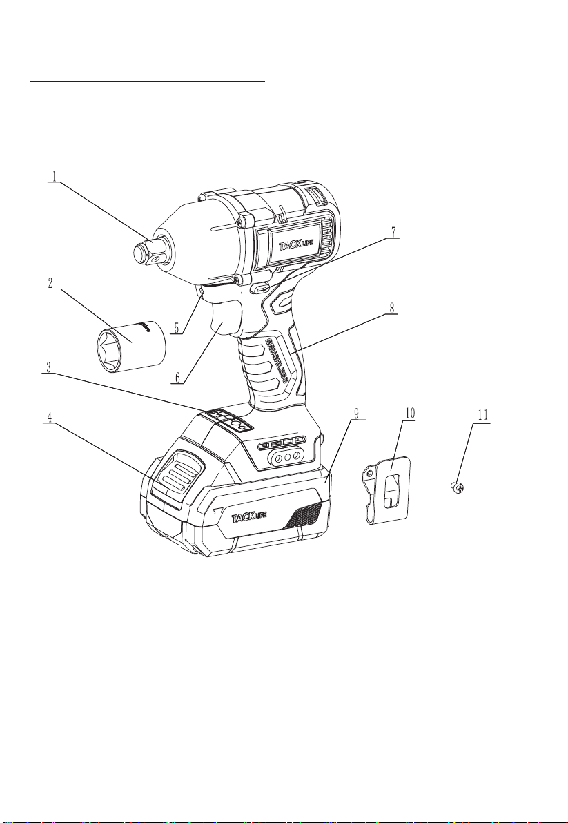
Before carrying out any work on the power
tool, move the direction pre-selector
switch (7) to the middle position.
Operate the direction pre-selector
switch (7) or Speed control panel
(3) only when the tool is stopped.
Identify the power tool with stickers only.
Do not drill any holes into the housing.
It is recommended that the bolting time
should not exceed 15 seconds.
Noise
and
vibration
NOTE
The noise and vibration values have been
determined in accordance with EN 62841.
The values are set out in the “Technical
data” table.
WARNING!
The indicated measurements refer to new
power tools. Daily use causes the noise and
vibration values to change.
NOTE
The vibration emission level given in this
information sheet has been measured in
accordance with a measurement method
standardized in EN 62841 and may be used
to compare one tool with another. It may be
used for a preliminary assessment of
exposure. The specified vibration emission
level represents the main applications of the
tool.
However, if the tool is used for different
applications, with different cutting
accessories or poorly maintained, the
vibration emission level may differ.
This may significantly increase the
exposure level over the total working period.
To make an accurate estimation of the
vibrationexposurelevel,itisalsonecessaryto
take into account the times when the tool is
switchedofforrunningbutnotactuallyinuse.
This may significantly decrease the exposure
level over the total working period.
Identify additional safety measures to protect
the operatorfromthe effectsof vibration such
as: maintain the tool and the cutting
accessories, keep the hands warm,
organization of work patterns.
CAUTION!
Wear ear defenders at a sound pressure
above 85 dB(A).
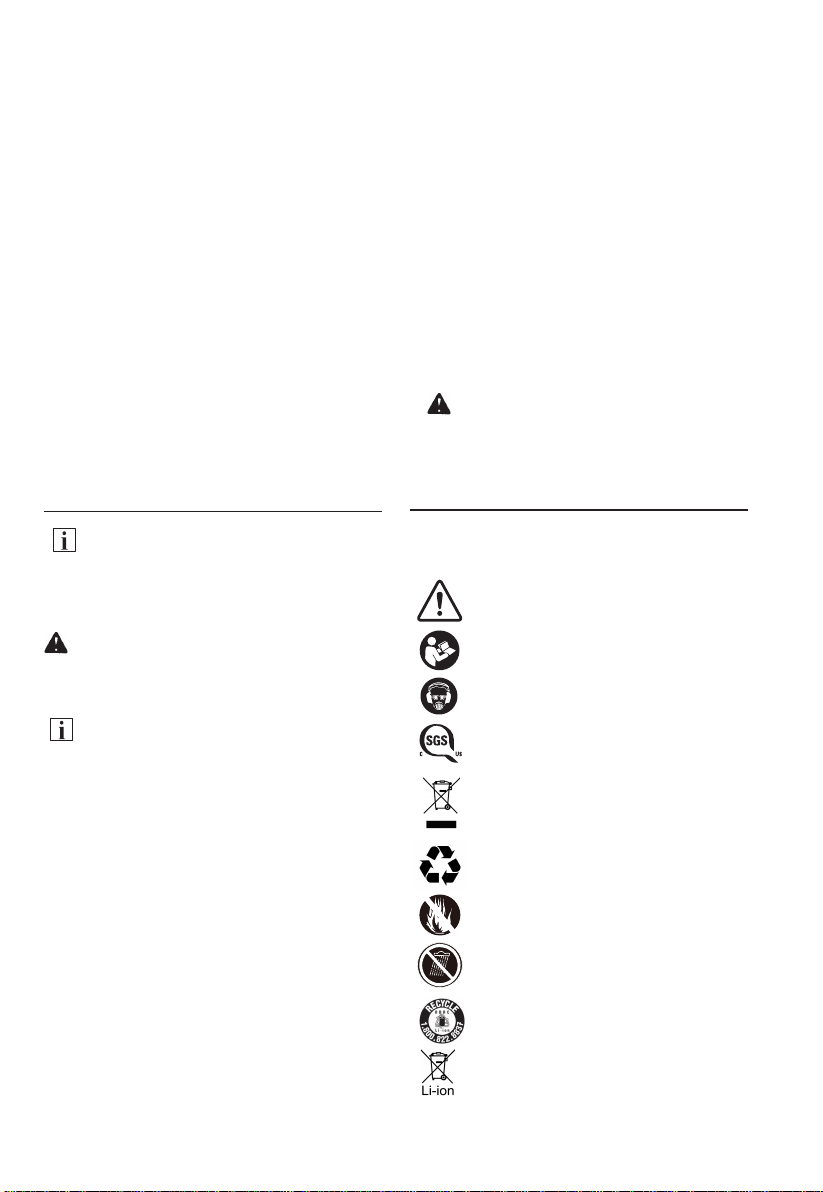
In this manual and/or on the machine the following
symbols are used:
Symbols
800295
WARNING / CAUTION
WARNING – To reduce the risk of injury,
user must read instruction manual.
Wear eye and ear protection and dust
mask.
Comply with relevant UL and CSA
regulations.
Dispose this appliance according to the
regulations and requirement of the local
council.
Do not dispose of battery packs in fire.
They will explode and cause injury.
Do not expose to rain or wet
conditions.
This appliance can be
recycled.
This appliance can be
recycled.
Batteries and battery pack should not be
disposed of with household waste.