Tactical PEA User manual

Power Enclosure Assembly
Instruction Manual
Contents
Introduction................................................................
...........................
2
Block diagram ................................................................
.......................
2
Description ................................................................
............................
3
External layout diagram ................................................................
........
5
Installation................................................................
.............................
6
Mirror protection................................................................
...................
7
Wiring list................................................................
..............................
8
Wiring diagram................................................................
....................
10
Specification................................................................
........................
11
References................................................................
...........................
11
Ordering information................................................................
...........
12
Supplier information................................................................
............
12
Copyright (C) 1994-8 Tactical Controls Limited
This document contains proprietary information which is protected by copyright. All rights reserved. This document or parts thereof may not
be reproduced in any form without written permission of the publishers.
The information in this document is subject to change without notice and should not be construed as a commitment by Tactical Controls
Limited. Tactical Controls Limited shall not be liable for errors contained herein or for incidental or consequential damages in connection
with the furnishing, performance or use of this material.

Tactical Controls Limited Power Enclosure Assembly Instruction Manual
Introduction
This document is the Instruction Manual for the Power Enclosure Assembly as specified in
the Critical Item Design Specification (CIDS) for the Power Cabinet (PCAB) HWCI of the
Power and Air (PAIR) HWCI of the Infantry Weapons Training Simulator (IWTS) Segment,
Thomson Training & Simulation Limited, Document Number 46 486 649-532B, 1994.
The Power Enclosure Assembly (PEA) of the Infantry Weapon Training Simulator, is
required to work in a standard class room, powered by 215 to 240V single phase 50Hz, 16A
European mains with outlets rated at 10A.
The cabinet is to house the following equipment: DC power supplies, Projector Dimmer
Controller, Vacuum motor with its controller and Inverter and Mirror protection circuitry,
Mains distribution, Elapsed time counter, mains switch, and the mains circuit breakers.
Block diagram
ALL DIMENSIONS ARE IN MM. GENERAL TOLERANCE X = +/-0.5 X.X = +/-0.05
All Righ ts Reserve .
C
Filenam e:
Size:
Drawing No.:
Title:
Tactical Controls Limite
Rev. Descripti on Iss. Chk. Auth . Date
A3
DIMMER CONTROL
PEA - BLOCK DIA GRAM
PEA\DWG\BLOCK
BLOCK
DC SUPPLIES
+5V
-5V
+12V
VACUUM CONTROL
VACUUM MOTOR
AIR
INTAKE
L1
N1
E1
MAINS
INPUT 1
L LN E N E
INSTRUCTORS
STATION
FIRING
STATION
DISTRIBUTION
+12V
-12V
+24V
+24V
COMMS. CONTROL
DC OUTPUT SK1
DC OUTPUT SK2
TO PROJECTORS
DIMMER OUTPUT
COMPUTER INTERFACE
SK3
MAINS
+
INVERTER
MAINS INDICATORS
MAINS CIRCUIT BREAKERS
ELAPSED TIME COUNTER
MAINS SWITCH
24V 0V OP
MIRROR POSITION LIMIT
SWITCH
+
PROTECTION
+
FAULT INDICATOR
3 PRODUCT ION ISSUE 26-SEP-199 7
L N E
SK4
MAINTENANCE SOCKET
MAINS CONTACTOR
REMOTE
STOP
pea\im Page 2 16 March 1998
Issue 4.0

Tactical Controls Limited Power Enclosure Assembly Instruction Manual
Description
The cabinet housing the power equipment is a floor standing or wall mounting steel enclosure
with a lockable front door. The wiring and equipment are designed to work from a 215 to
240Vac 50Hz single phase supply.
The enclosure is designed to embrace the following:-
1. A key lockable door which restricts access to users whilst powered ON but providing
access to authorised servicing personnel.
2. A vacuum pump, fitted on anti-vibration mounts.
3. A door mounted power elapsed time indicator, non-resetable. This is powered from one
of the mains poles after the power latch start button.
4. A door mounted 4 poles mains switch.
5. The following equipment are DIN rail (EN 50 022) mounted:-
- Two poles of incoming mains (2.5 or 4 mm2type) with
Pole 1 1 live, 1 neutral and 1 earth terminal points
Pole 2 1 live, 1 neutral and 1 earth terminal points
- Two poles of distributed mains (2.5 or 4 mm2type) with a minimum of
Pole 1 8 live terminals points
8 neutral terminals points
Pole 2 8 live terminals points
8 neutral terminals points
Common earth consisting of 16 earth terminals points.
- Four terminals points for dimmer output.
- Two 10 amp Circuit breakers.
- Twelve terminals points for mirror position sensor input, limit switch input and mirror
protection circuitry.
- One output and one control relay for mirror protection circuitry.
- One push to break button to reset mirror fault latch circuitry.
6. DC Power supplies designed to provide the following:-
+24V at 4A
+12V at 20A
-12V at 1.5A
+5V at 8A
-5V at 1.5A
The +12V and its return have a remote sense and local setting voltage of 12.6V +/- 1V.
7. A 3-phase vacuum motor controller (Ref: Tactical 305MC) and inverter (Ref:
Mitsubishi FR-U120S-0.4K-ER) which is wired for the vacuum motor.
8. Test points are provided to monitor the vacuum sensor output to enable the vacuum
motor controller to be set-up.
9. The cabinet has a vacuum output on the gland plate for a 55 mm outside diameter pipe.
pea\im Page 3 16 March 1998
Issue 4.0

Tactical Controls Limited Power Enclosure Assembly Instruction Manual
10. A projector dimmer controller (Ref: Tactical 150LD).
11. A dimmer data external cabinet connector. This is made via a DIN 5-way audio socket
connector 240º twist lock bayonet (PREH) type (Ref: RS 453-448).
12. Dimmer controlled mains internal connection is to be wired via two DIN rail mounted
terminal blocks.
13. External cable glands:
3 off PG9 (for DC supplies and data).
8 off PG11 for mains and DC supplies.
14. DC supplies external cabinet connectors are via 2 off Thomas and Betts 9-way chassis
mounted sockets (Ref: RS 484-341). These are wired with key "A" and "B" orientation.
The contacts are 0.75 to 1.5mm2wire type.
15. The cabinet dimensions are 700mm high x 700mm wide x 300mm deep. These are to be
exclusive of floor mounting feet, glands, connectors and buttons.
16. There is provision for wall mounting via 4 off 8mm inverted key hole at the back of the
cabinet and floor free standing on 4 rubber feet.
17. The paint finish is colour Green RAL 6031 Matt.
18. The casing and door are earthed.
19. Internal wiring are made to drawings 46 486 649-197.
20. The following labels are located at suitable locations and without any language
dependant text:-
High voltage symbol inc voltage range "215 - 240V" and frequency "50Hz".
Earth Point symbol
21. Suitable vents are provided to enable the vacuum exhaust to operate.
22. Two off, door mounted low profile neon lamps (green) are fitted to indicate the status of
each of the two poles of mains supply after the circuit breakers.
23. One off, door mounted low profile filament lamp (red) is fitted to indicate any mirror
fault.
24. One off, 20 meters 2 core cable connected to a remote stop button is fitted.
25. One off, door mounted green push button for the start of the power cabinet.
26. One off, 15 meters 3 core mains cable ended with Schuko mains plug is connected to
both poles.
27. One off, Schuko mains socket is fitted on the right gland plate for test equipment.
pea\im Page 4 16 March 1998
Issue 4.0

Tactical Controls Limited Power Enclosure Assembly Instruction Manual
External layout diagram
ALL DIMENSIONS ARE IN MM. GENERAL TOLERANCE X = +/-0.5 X.X = +/-0.05
All Rights Reserve .
C
Filename:
Size:
Drawing No.:
Title:
Tactical Controls Limite
Rev. Description Iss. Chk. Auth. Date
A0
PEA\DWG\LAYOUT-E
LAYOUT-E
POWER ENCLOSURE ASSEMBLY EXTERNAL LAYOUT
3.0 ADD START BUTTON 8-JUN-1997
RAL6031 PAINT FINISH
300.0
700.0
1 KEY OPERATED DOOR LOCK
2 DOOR HINGES
700.0
20 OFF 3X25MM AIR VENT
ON BOTH SIDES OF CABINET
ON A 240X120 GLAND PLATE
STEEL CABINET TO BE BOTH
WALL MOUNTED THROUGH
4 X M8 INVERTED KEYHOLE
AT FOUR CORNERS
AND FREE STANDING
ON 4 RUBBER FEET
8 PG11 CABLE GLANDS
D-SHAPED DOOR HANDLE
ELAPSED TIME COUNTER
20.0
150.0
M5X15 STUD ON BOTH SIDES OF CABINET
55.0
590.0
55.0600.0
2 POWER INDICATORS1 FAULT INDICATOR
4 INVERTED KEYHOLES
FOR WALL MOUNTING
MAINS SWITCH
4 RUBBER FEET
START BUTTON
pea\im Page 5 16 March 1998
Issue 4.0

Tactical Controls Limited Power Enclosure Assembly Instruction Manual
Installation
The cabinet is suitable for either wall mounting on 4 off 8 mm inverted key holes at the back
of the cabinet, or floor free standing on 4 off rubber feet.
All connections to the cabinet are made either using plugs and sockets at the gland plate or
through terminations on the DIN railed mounted terminal block inside the cabinet. All cable
entries or exits are via cable glands on cable gland plates on either side of the cabinet.
The cabinet provides the following external connections:-
1. Incoming power 1 L1, N1 and E1 on TB2-1, 2 and 3
Incoming power 2 L2, N2 and E2 on TB2-4, 5 and 6
The two poles are connected to a 15 meters 3 core mains cable with a Schuko plug
fitted.
2. Mains distribution to Compressor L, N and E on TB1-1, 5 and 22
Mains distribution to Instructors station L, N and E on TB1-11, 15 and 23
Mains distribution to Firing station L, N and E on TB1-12, 16 and 24
3. DC power supplies
+12V, +5V, -5V and +12 sense Panel mounted socket SK1
+12V, -12V, +24V and earth Panel mounted socket SK2
+24V for comms control Terminal 2 and 7 on PS1
4. Dimmer output to Projectors L, N and E on TB1-25 and 26
5. Computer interface for dimmer control Panel mounted socket SK3
6. Position sensor for mirror control 24V, 0V and O/P on TB1-27, 28 and 29
7. Mirror limit switch N/C, COM and N/O on TB1-30, 31 and 32.
8. Remote stop Fitted with 20 meters 2 core cable
In addition, the air intake is made using a 55mm outside diameter pipe connected to the
vacuum pump motor air-inlet with provision for the pipe to go through the gland plate.
pea\im Page 6 16 March 1998
Issue 4.0

Tactical Controls Limited Power Enclosure Assembly Instruction Manual
Mirror protection
The mirror is protected from excess vacuum which can cause permanent damage to the
mirror. The minimum distance of the mirror from the supporting frame is set by the position
of a limit switch. The limit switch is normally closed which enables the ultra-sonic transducer
and the inverter.
When the mirror hits the limit switch due to excessive vacuum, which could be due to faulty
sensor or faulty control, the latching relay is energised and latched. Both the ultra-sonic
transducer and the inverter are disabled. The fault lamp is lit indicating the presence of mirror
fault.
Provided the fault no longer exists, the latching circuit can be cleared by either pressing the
Reset button or turning off the power,
Please refer to the following diagram for further details.
ULTRA-SONIC
TRANSDUCER
LATCHING RELAY
FAULT
ALL DIMENSIONS ARE IN MM. GENERAL TOLERANCE X = +/-0.5 X.X = +/-0.05
2
LAMP
L3
2
RESET
BUTTON
PB1
1
LIMIT SWITCH
1
A2
A1
11
21
24
RL2
12
PRODUCTION ISSUE
Rev.
1
Description Iss. Chk.
A2
VACCUM
PUMP
MOTOR
Tactical Controls Limited
Mirror fault detection circuitry
MF-DET
Filename:
Drawing No.:
Title:
Auth. Date
All Rights Reserved.
C
A4
Size:
PEA\DWG\MF-DET
INVERTER
A3
N
A1 14
11
RL1
21
24V
MOTOR CONTROL RELAY
24
240VAC
TB1-30
TB1-31
TB1-32
TB1-27
TB1-28
1-MAR-1995
pea\im Page 7 16 March 1998
Issue 4.0

Tactical Controls Limited Power Enclosure Assembly Instruction Manual
Wiring list
W ire T e rm i- T e rm i-
N o . D e sc rip tio n F ro m n a tio n T o n a tio n C o lo u r S iz e
1 CB 1 to TB 1 TB 1-1 B ootlac e C B 1-1 B ootlac e B rown A W G 16
2 Inverter F ilter 1 Live TB 1-2 B ootlac e R L1-21 S blade B row n A W G 16
2 Inve rte r F ilte r 1 re lay R L1-2 1 S blad e R L1 -11 B o otla c e B ro w n A W G 16
3 Tim er Live TB 1-3 B ootlac e TE I-1 S older B row n A W G 16
4 L1 Live TB 1-4 B ootlac e L1-1 F as ton B row n A W G 16
5 C1 to TB 1 TB 1-5 B ootlac e C 1-4 M 4 fork B lue A W G 16
6 Inverter F ilter N eutral TB 1-6 B ootlac e F L1-L/N B ootlac e B lue A W G 16
7 Tim er N eutral TB 1-7 B ootlac e TE I-2 S older B lue A W G 16
8 L1 N eutral TB 1-8 B ootlac e L1-2 F as ton B lue A W G 16
9 F ilter2 to TB 1 TB 1-9 B ootlac e F L2-O /L F as ton B row n A W G 16
9 D im m er Live TB 1-9 B ootlac e A 1-L M 4 fork B row n A W G 16
10 P S 3 Live TB 1-10 B ootlac e P S 3-L M 4 fork B row n A W G 16
10 L2 Live TB 1-10 B ootlac e L2-1 F as ton B row n A W G 16
11 P S 2 Live TB 1-11 B ootlac e P S 2-L M olex B row n 24/02
12 P S 1 Live TB 1-12 B ootlac e P S 1-L M 4 fork B row n A W G 16
13 F ilter2 to TB 1 TB 1-13 B ootlac e F L2-O /N F as ton B lue A W G 16
13 D im m er N eutral TB 1-13 B ootlac e A 1-N M 4 fork B lue A W G 16
14 P S 3 N eutral TB 1-14 B ootlac e P S 3-N M 4 fork B lue A W G 16
14 L2 N eutral TB 1-14 B ootlac e L2-2 Fas ton B lue A W G 16
15 P S 2 N eutral TB 1-15 B ootlac e P S 2-N M olex B lue 24/02
16 P S 1 N eutral TB 1-16 B ootlac e P S 1-N M 4 fork B lue A W G 16
17 D im m er E arth TB 1-17 B ootlac e A 1-E M 4 fork G N/Y L A W G 16
18 C ontroller E arth TB 1-18 B ootlac e A 2-13 M 3 ring G N /Y L A W G 16
19 P S 3 E arth TB 1-19 B ootlac e P S 3-E M 4 fork G N/Y L A W G 16
19 Inverter E arth TB 1-19 B ootlac e A 3-E F ree G N/Y L A W G 16
20 P S 2 E arth TB 1-20 B ootlac e P S 2-E M olex G N /Y L 24/02
20 C abinet E arth TB 1-20 B ootlac e Cabinet M 5 ring G N /Y L A W G 16
21 P S 1 E arth TB 1-21 B ootlac e P S 1-E M 4 fork G N/Y L A W G 16
21 M otor E arth TB 1-21 B ootlac e M 1-E M 4 ring G N /Y L A W G 16
22 S K 2 E arth TB 1-22 B ootlac e S K 2-9 C rim p G N /Y L 24/02
22 F L1 E arth TB 1-22 B ootlac e F L1-E B ootlac e G N /Y L A W G 16
23 F L2 E arth TB 1-23 B ootlac e F L2-E F as ton G N /Y L A W G 16
23 E xternal wiring TB 1-23
24 E xternal wiring TB 1-24
25 D im m er output live TB 1-25 B ootlac e A 1-O P M 4 fork B row n A W G 16
26 D im m er output neutral TB 1-26 B ootlac e A 1-N M 4 fork B lue A W G 16
27 Tra ns duc er s up ply TB 1-2 7 B ootlac e R L2-11* S blad e B lac k 24/02
27 R L1 c oil s up ply R L2-11* S blade R L1-A 1 B ootlac e B lac k 2 4/02
28 0V c om m on TB 1-28* L blade A 2-24 M 3 ring B lac k 24/02
28 TB 1-28* L blade P S 1-5* M 4 fork B lac k 24/02
28 R L1-A 2* S blade P S 1-5* M 4 fork B lac k 24/02
28 R L1-A 2* S blade P B 1-1* L blade B lac k 24/02
28 L3-2 F as ton P B 1-1* L blade B lac k 24/02
28 P S 2-4 M olex S K 1-4 C rim p B lac k 24/02
28 P S 3-8 M 4 fork P S 2-13 M olex B lac k 24/02
28 P S 2-6 M olex P S 2-11 M olex B lac k 24/02
28 P S 2-7 M olex P S 3-15* M 4 fork B lac k 24/02
28 P S 3-15* M 4 fork P S 1-6* M 4 fork B lac k 24/02
28 P S 1-7* M 4 fork S K 2-6 C rim p B lac k 24/02
28 P S 3-14* M 4 fork S K 1-1 Crim p B lac k 24/02
28 P S 3-14* M 4 fork S K 2-1 Crim p B lac k 24/02
28 P S 1-7* M 4 fork S K 1-8 C rim p B lac k 24/02
29 Tra ns duc er in put TB 1 -29 B ootla c e A 2 -23 M 3 ring B lac k 24/02
30 Lim it s w itc h N /C TB 1-30 B ootlac e R L2-12 B ootlac e B lac k 24/02
31 24V TB 1-31 L blade P S 1-3 M 4 fork B lac k 24/02
31 24V P S 1-4 M 4 fork S K 2-8 C rim p B lac k 24/02
31 M irror m onitor TB 1-31 L blade RL2-21 B ootlac e B lac k 24/02
32 L im it s w itc h N /O TB 1 -32 L b la de R L 2-24 S bla de B la c k 24/02
32 F ault lam p s upply TB 1-3 2 L bla de L3-1 F as ton B lac k 2 4/02
32 R L2 c oil s up ply R L2-24 S b lade R L2-A 1 B o otlac e B lac k 24/02
pea\im Page 8 16 March 1998
Issue 4.0

Tactical Controls Limited Power Enclosure Assembly Instruction Manual
33 R es et bu tton P B 1-2 B oo tlac e R L2 -A 2 B oo tlac e B lac k 2 4/02
34 5V P S 2-2 M o le x S K 1-3 C rim p B la c k 2 4/0 2
34 5V P S 2-3 M o le x S K 1-5 C rim p B la c k 2 4/0 2
35 -5V P S 2-12 M ole x S K 1-6 C rim p B lac k 24/02
36 12V P S 3-12 M 4 fork S K 1-2 C rim p B lac k 24/0 2
36 12V P S 3-13 M 4 fork S K 2-2 C rim p B lac k 24/0 2
37 -12V P S 2-10 M ole x S K 2-5 C rim p B lac k 24/02
38 12V s ens e+ P S 3-11 M 4 fork S K 1-7 C rim p B lac k 24/0 2
39 12V s ens e- P S 3-16 M 4 fork S K 1-9 C rim p B lac k 24/0 2
40 M oto r B lue p has e A 3-U F ree M 1-U M 4 ring B lu e A W G 1 6
41 M oto r R e d ph as e A 3-V F re e M 1 -V M 4 rin g B ro w n A W G 16
42 M oto r Y ello w ph as e A 3-W F ree M 1-W M 4 rin g Y e llow A W G 16
43 C ontro lle r+ to F ilter 3 A 2 -20 M 3 rin g F L3 -L/L F as to n B lac k 24/02
44 C ontro lle r- to F ilte r 3 A 2 -2 1 M 3 ring F L3 -L /N F as to n B la c k 24 /02
45 F ilte r2 to C B 2 F L 2-L/L F as ton C B 2-1 B oo tlac e B row n A W G 16
46 F ilte r2 to C 1 F L 2-L/N F as ton C 1-8 M 4 fork B lue A W G 1 6
47 C B 1 to C 1 C B 1-2 B o otla c e C 1 -2 M 4 fork B row n A W G 16
48 C B 2 to C 1 C B 2-2 B o otla c e C 1 -6 M 4 fork B row n A W G 16
49 D im m e r to S K 3 -1 A 1-0V B o otlac e S K 3-1 S o ld er B la c k 2 4/0 2
50 D im m e r to S K 3 -2 A 1-D B oo tlac e S K 3 -2 S olde r B lac k 2 4/02
51 D im m e r to S K 3 -3 A 1-C B oo tlac e S K 3 -3 S olde r B lac k 2 4/02
52 D im m e r to S K 3 -5 A 1-S B oo tlac e S K 3-5 S old er B lac k 24/02
53 C on trolle r Live F L1-O /L S bla d e A 2-14 M 3 rin g B ro w n A W G 16
53 C urre nt L im iter L ive F L1 -O /L S bla de R 1 -1 S o ld er B ro w n A W G 16
54 C on trolle r N eutral F L1-O /N S bla de A 2-1 6 M 3 ring B lue A W G 16
54 Inverter N eu tral F L 1 -O /N S b lade A 3 -N F ree B lue A W G 16
55 F ilte r 1 L ive R L1 -2 4 S b la de F L 1-L/L B o otla c e B ro w n A W G 16
55 F ilte r 1 re lay R L1 -2 4 S b la de R L 1-14 B o otlac e B ro w n A W G 16
56 F ilte r 3 to Inverte r+ F L3 -O /L F as to n A 3 -2 F ree B lac k 24 /02
57 F ilte r 3 to Inverte r- F L3-O /N F a s ton A 3 -5 F re e B la c k 24/0 2
58 TB 2 L 1 to L2 TB 2-1 L bla de TB 2 -4 L blad e B ro w n A W G 1 6
58 S w itc h1 L1 to TB 2 TB 2 -1 L b la de S W 1 -1 M 4 fork B row n A W G 16
58 S w itc h1 L2 to TB 2 TB 2 -4 L b la de S W 1 -3 M 4 fork B row n A W G 16
59 S w itc h1 N 1 to TB 2 TB 2 -2 L blad e TB 2 -5 L blad e B lu e A W G 1 6
59 TB 2 N 1 to N 2 TB 2 -5 L blad e S W 1 -5 M 4 fork B lue A W G 16
59 S w itc h1 N 2 to TB 2 TB 2 -5 L blad e S W 1 -N 7 M 4 fork B lue A W G 16
60 TB 2 to TB 1 E a rth TB 2-3 B o o tlac e TB 1-1 7 B o otlac e G N /Y L A W G 16
63 TB 2 to TB 1 E a rth TB 2-6 B o o tlac e TB 1-1 8 B o otlac e G N /Y L A W G 16
64 S w itc h1 to C 1 C 1 -3 M 4 fork S W 1 -6 M 4 fo rk B lu e A W G 16
64 S w itc h1 to TX1 S W 1-6 M 4 fork TX1 -P 0 non e B lue
64 C 1 to S K 4 C 1-3 M 4 fo rk S K 4-N M 4 fork B lue A W G 16
65 C 1 to S w itc h 1 C 1-7 M 4 fork S W 1-N 8 M 4 fork B lue A W G 16
66 F S 1 to S w itc h1 F S 1-1 L bla de S W 1 -2 M 4 fork B row n A W G 16
66 C 1 to F S 1 C 1-1 M 4 fork F S 1-1 L b lade B ro w n A W G 16
66 S w itc h1 to TX1 S W 1-2 M 4 fork TX1 -P 2 40 non e B row n
67 C 1 to S w itc h 1 C 1-5 M 4 fork S W 1-4 M 4 fork B row n A W G 16
68 F S 1 to S K 4 F S 1 -2 B oo tlac e S K 4-L M 4 fork B row n A W G 16
69 TX1 to F S 2 TX1 -2 4V non e F S 2 -2 F re e Y ellow
70 F S 2 to C 1 F S 2-1 B o o tlac e C 1 -A 1 M 4 fork B lac k 24/02
71 C 1 to S B 2 C 1-A 2 M 4 fo rk S B 2-3 M 4 fork B row n A W G 16
71 C 1 to C 1 C 1-A 2 M 4 fork C 1/-4 M 4 fo rk B ro w n A W G 1 6
72 TB 3 to TX1 TB 3-1 F ree TX1 -S 0 non e B lac k
73 C 1 to TB 3 C 1/-3 M 4 fork TB 3-2 B oo tlac e B row n A W G 16
73 C 1 to S B 2 C 1/-3 M 4 fork S B 2-4 M 4 fork B row n A W G 1 6
74 Inverter L ive R 1-2 S old e r A 3-L1 F re e B ro w n A W G 1 6
F ilte r 1 E a rth F L 1 -O /E B ootla c e E arth M 5 rin g G N /Y L A W G 16
F ilte r 3 E a rth F L 3 -E F as ton E a rth M 4 rin g G N /Y L A W G 16
P S 1 E a rth P S 1-6 M 4 fork E arth b ar M 5 rin g G N /Y L A W G 16
P S 2 E a rth P S 2-5 M o lex E arth ba r M 5 rin g G N /Y L 24 /02
P S 3 E a rth P S 3-8 M 4 fork E arth b ar M 5 rin g G N /Y L A W G 16
S K 2 L o c a l E arth S K 2 -3 C rim p E a rth M 4 rin g G N /Y L 24 /02
D oo r E arth D oo r M 5 rin g C a bine t M 5 rin g G N /Y L A W G 16
S K 4 L o c a l E arth S K 4 -E B ootlac e E arth M 4 ring G N /Y L A W G 16
M oto r E arth M o tor M 8 rin g E arth M 8 ring C le ar B raid 25
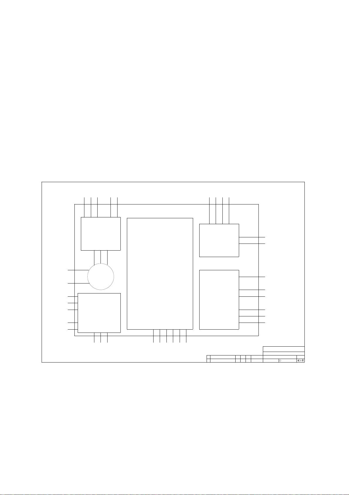
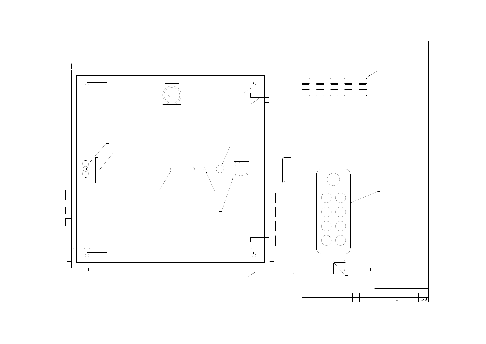
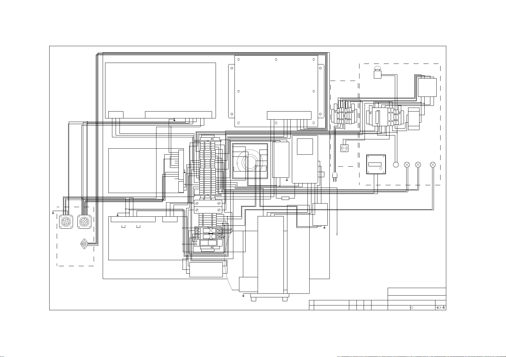
Please refer to the wiring diagram for their exact locations.
pea\im Page 9 16 March 1998
Issue 4.0

Tactical Controls Limited Power Enclosure Assembly Instruction Manual
Wiring diagram
MOTOR
PS3 DIMMER
INVERTER
CONTROLLER
TB1
A1
A3
A2
BACK PLATE
SMS300/12
SMS100/24 M1
PS2
PS1
SLMC75R/06
1 2
3
45
GLAND PLATE
SK3
1
2
3
4
5
6
789
SK2
123
4
5
6
78 9
SK1
FILTER
FL3
FILTER
FL2
5
6
7
8
25
26
FILTER
FL1
VIEW FROM INSIDE
1 2 3 4 5 6
VIEW FROM INSIDE
INSIDE CABINET
1
2
3
4
9
10
11
12
13
14
15
16
17
18
19
20
21
22
23
24
CB1
0-OFF
1-ON
CB2
0-OFF
1-ON
27
28
29
30
31
32
RL1
RL2
PB1
RP330024
RP420024
R1
SW1
MAINS SWITCH
C1
CONTACTOR
SK4
SCHUKO SOCKET
TB2
TB3
TX1
TRANSFORMER
1 2FS1 FS2
L1 L3
ON THE DOOR
VIEW FROM INSIDE
L2
TIMER
COUNTER
TEI SB2
SB1
EMERGENCY STOP
1 2
1 2
24 21
14 11
24 21
14 11
22 A2
A112
22 A2
A112
1 5 3 N7
2 6 4 N8
1
2
753
4 6 8
A1
A2
0
2400
24
-4
-3
1 2 3
E
N
L
5
3
1
E N L
5 4 3
L N E
20
21
E
14/L
16/N
STF
SD
VE
2
5
1 2 3 4 5 6 7 8 9 10 11 12 13 14 15 16
0V
1
9 12345678
V+V+V- V-S- S+
S+ S-V-V-V+V+
+5
+5
+5
0V
0V
0V
2
3
4
5
6
7
8
9
10 -12V
-5V
0V
0V11
12
13
0V
N E
6 7
N
9 10 11 1221
L
5
STROBE
CLOCK 0V
DATA
OP
843
X X X
TO CABINET EARTH STUD
& DOOR EARTH STUD
23
24
1
5
19 19
L1 N E U V W
U W
N
LINE
L
NL E
NL
NL E
LOAD
L
N
E
L
N
LINE LOAD
LOAD
LINE
E
21
1 2
3 4
All Rights Reserve .
C
Filename:
Size:
Drawing No.:
Title:
Tactical Controls Limite
Rev. Description Iss. Chk. Auth. Date
A0
PEA - POWER ENCLOSURE ASSEMBLY WIRING
PEA\DWG\WIRING
WIRING
ALL DIMENSIONS ARE IN MM. GENERAL TOLERANCE X = +/-0.5 X.X = +/-0.05
2
1
LINK L1 AND L2; NEW PUSH BUTTON3.4 3-NOV-1997
20M 2 CORE BLACK
MP1
SCHUKO PLUG
15M 3 CORE BLACK
pea\im Page 10 16 March 1998
Issue 4.0

Tactical Controls Limited Power Enclosure Assembly Instruction Manual
Specification
Mains distribution 3 off 240Vac outlets.
DC supplies +24V at 4A.
+12V at 20A with remote sense and local setting.
-12V at 1.5A.
+5V at 8A with local setting.
-5V at 1.5A.
Connections via 2 off 9-way chassis mounted sockets and +24V to
comms control.
Dimmer control Computer interface via DIN 5-way audio socket.
Dimmer output via DIN-rail mounted terminal blocks.
For detail, see 150LD instruction manual.
Vacuum control Position sensor, limit switch and 24V via DIN-rail mounted terminal
blocks; air intake via 55mm outside diameter pipe.
For detail, see 305MC instruction manual.
Reliability MTBF of not less than 1000 hours.
Supply 215 to 240Vrms +/-5%, 50Hz +/-1%
Temperature 0 to 50 ºC operating; -20 to 65 ºC storage
Dimensions 700mm(H) x 700mm(W) x 300mm(D)
Mounting positions Wall mounted on fixing centres 590 x 600mm
or free floor standing on 4 rubber feet
Weight 65Kg max.
References
"Critical Item Design Specification (CIDS) for the Power Cabinet (PCAB) HWCI of the
Power and Air (PAIR) HWCI of the Infantry Weapons Training Simulator (IWTS) Segment",
Thomson Training & Simulation Limited, Generic Weapons Training Simulator, Document
Number: 46 486 649-532B, 1994.
"Schematic diagrams for the power cabinet", Thomson Training & Simulation Limited,
drawing no: 46 486 649-197, June 1994, Rev.A.
305MC Instruction Manual
Mitsubishi General Purpose Inverter FREQROL-U120S-ER Instruction Manual
150LD Instruction Manual
pea\im Page 11 16 March 1998
Issue 4.0

Tactical Controls Limited Power Enclosure Assembly Instruction Manual
Ordering information
Ordering code: PEA
You are welcome to order the unit by code or description - PEA Power Enclosure Assembly.
Supplier information
Tactical Controls Limited
Unit 4 Marlborough Road
Lancing, West Sussex BN15 8TR
England
Tel: (01903) 750800
Fax: (01903) 750678
pea\im Page 12 16 March 1998
Issue 4.0
Table of contents