Tar River BDR-135 User manual

1
Publicaon #: January 2014
Drum Mower
Operator’s Manual
Parts Breakdown
Models:
BDR-135
BDR-165
BDR-185

2
TABLE OF CONTENTS
Introduction 3
Saftey Rules 4
Partial Risks 5
General Information 6
Operational Service 8
Connecting the Mower with the Tractor 8
Assembly of the PTO Shaft 9
Adjusting the Mower to Transport Position 10
Adjusting the Mower to Operational Position 12
Adjusting the Mower 14
Operating the Mower 16
Resting Position 17
Technical Maintenance of the Mower 18
Changing the Blades 18
V-Belt Tension 19
Everyday Maintenance 20
Post-Season Maintenance 20
Lubrication Instructions 20
Transport Lights 22
Assembly of Mower 23
Troubleshooting 24
Parts Breakdown 25
Warranty 45

3
INTRODUCTION
Thank you for purchasing your Tar River Drum Mower. This Operator’s Manual is available with every machine for
the purpose of introducing the user to the design, maintenance, and adjustment of the mower. It will also warn
against any possible threats. The Operator’s Manual includes information regarding the adjustment and transport on
the public roads.
Following the instructions carefully will ensure many years of damage-free and safe operation and will result in de-
creasing of the operational costs of the machine.
If you have any questions after reading this manual, please contact the Sales Representative or the Sales and Market-
ing Department.
To emphasize the importance of the information and the warnings of possible hazards, the following warning symbol
with a description has been used:
If you see this symbol, be aware of a threat, carefully read the appropriate information and inform other operators
about it.
The mower has a name plate placed on the middle frame with basic machine identification infor-
mation.
The warrantee proceedings rules and the rules resulting from them are written in the warrantee card, which is an inte-
gral part of the Operator’s Manual.
The Operator’s Manual is part of the basic equipment of the machine and it should be kept for future use.
PRODUCT PURPOSE
The purpose of the Drum Mower is to be used in farming to mow the low stem green fodder (alfalfa grass, etc.) in the
fields and meadows.
Operating the mower in alternate conditions will be considered a misuse. Strict compliance with the requirements for
the use of the machine as well as its servicing and repairs by the manufacturer is a prerequisite for the intended use.
The machine should be used, operated and maintained only by persons who are familiarized with its specifics as well
as with the work safety proceedings rules.
The provisions regarding preventing accidents and all basic work safety and hygiene rules as well as the traffic regu-
lations must always be observed.
Any changes made to the machine without the consent of the manufacturer will exempt the manufacturer from the
responsibility for any possible damages resulting from them.

4
SAFETY RULES
PLEASE BE CAREFUL – READ THE OPERATOR’S MANUAL CAREFULY IN
ORDER TO PROTECT YOURSELF AND OTHERS FROM DANGER.
The machine should be used with respect to the basic work safety rules and the following precautions:
NEVER allow any unauthorized per sons, unfamiliar with the Oper ator ’s Manual or underage persons,
especially children, to use the machine.
ALWAYS check the physical condition of the machine, especially its wear and whether the oper ating ele-
ments of the cutting system are properly secured.
YOU MUST replace the wor n out or damaged par ts with new ones.
THE MACHINE may be oper ated only with the r ecommended tr actors equipped with the r equir ed front
axle load.
DURING the time of aggr egating the machine with the tractor , special car e should be exer cised, and it is
prohibited for any persons to be present between the machine and the tractor while the engine is on.
IT IS UNACCEPTABLE to oper ate the machine without the shields and a guard, it is also pr ohibited to
operate the machine with damaged shields and lifted guard.
IT IS UNACCEPTABLE to oper ate the hydraulic lift lever exter nally.
PRIOR TO ANY OPERATION activities per for med on the mower, it is necessar y to disengage the power
take-off drive and the engine of the tractor, pull out the key from the ignition, and allow the operating drums and
the blades to come to a complete stop.
WHILE perfor ming necessary operation activities required for the purpose of lifting the mower on the
three-point suspension system, it is very important to secure it additionally to prevent from detaching by a sup-
port or a chain.
IT IS PROHIBITED to lift the mower with the power drive tur ned on and the cylinders rotating.
IT IS NECESSARY to check whether there are any persons or animals within the danger zone pr ior to
turning the driving power on or during operating the mower.
IT IS PROHIBITED to operate the machine with any bystanders present within less than 50m perimeter.
THE FIELDS AND MEADOWS TO BE MOWED should be fr ee from any for eign and hard objects.
IT IS PROHIBITED to mow on the sides of the str eets, public r oads, public places (par ks, schools, etc.) or
places with stones in order to eliminate the risk of the hard objects thrown out.
THE MOWER SHOULD BE tur ned on only when in the oper ating position.
THE MOWING may be star ted only when the power take-off engine speed of 540 rev/min. is reached; it is
prohibited to surpass 600 rev/min.
IT IS PROHIBITED to operate the mower while driving backwards.
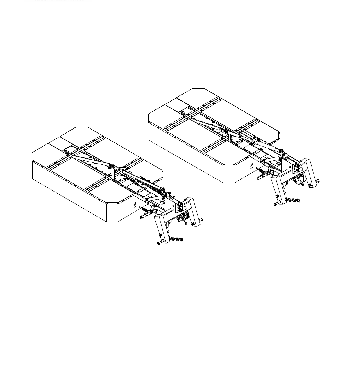
FOR TRANSPORT the mower should be in a transpor t position.
CHANGING the mower ’s position from the tr anspor t position to the oper ating position should be per-
formed on a horizontal and even surface, with the blades lifted above the ground.
IT IS UNACCEPTABLE to car r y on board any persons or any load while the machine is being tr anspor t-
ed or while operating it.
WHILE on the public road, applicable provisions of the Tr affic Regulations should be obeyed, and the
mower should be equipped with required lighting and warning devices in accordance to the local laws of a partic-
ular country, where the machine is used.
NOT APPLYING the r ules mentioned above may cause hazar d for the operator of the machine
and bystanders, as well as it may cause damage to the machine. For the damages resulting from the
failure to comply with these rules, the responsibility will be on the side of the mower’s user.

5
PARTIAL RISKS
The manufacturer has made every effort to ensure that the design and the intended method of operating the mower
does not cause any danger to people and their environment.
Due to the nature of the mower and the lack of such opportunities to fully expose the cutter, certain elements of risk
can occur.
THE DANGER caused by the pr esence of the shar p edges of the cutting system and the possi-
bilities of any hard objects thrown out, e.g. stones, broken blades, etc. The danger zone resulting
from the possibility of throwing out hard objects is within 150 ft. perimeter from the mower being
operated.
DANGER the wor king cylinders and the blades are still rotating for a certain amount of time
even after the power drive of the mower is turned off. Therefore, before proceeding with any work
activities on the mower, it is crucial to wait until the operating drums with the blades stop rotating.
DANGER changing the mower ’s position fr om the tr ansport position to the operating posi-
tion and backwards may be performed only on an even and flat surface after prior leveling of the
machine. Failure to comply with these conditions may cause the cutting system of the mower turn
around on its own on the suspension and hit or deform the operating elements of the tractor.
SAFETY SIGNS AND INSCRIPTIONS
There are warning labels placed on the mower with safety signs in the form of pictograms, which give clear instruc-
tions and comments informing about what should be treated with special precaution in order for the operation of the
mower to be safe.
Carefully read every warning label and get familiarized with their meaning.
The warning labels should be kept clean and readable throughout the whole life of operating the mower. In case the
warning labels are not readable, the damaged labels should be replaced with new ones.
New systems and parts replaced during any repairs should have all required warning labels. The new labels may be
obtained from stores or from the manufacturer, as it is done with any other spare parts.

6
GENERAL INFORMATION
Sales Information
The technical condition and the equipment of the mower should be checked at the time of purchase.
It should be required from the equipment dealer to carefully fill out the Warranty Registration Form. Failure to pro-
vide the date of purchase or the dealer’s information might cause the buyer to suffer disapproval of any possible com-
plaints.
Equipment and Spare Parts
The mower includes the following basic equipment:
The Operator’s Manual, Parts Breakdown and Warranty Registration Form 1pc.
Blade Changing Tool 1pc.
Blades (packed) 18pcs
Design and Operation
The design of the mower:
1. Suspension
2. Central beam
3. Push rods, hydraulic cylinders (depending on the
version)
4. Main frame
5. Shield system
6. Stump jumper
7. Operating drums
8. Protective shield
9. Lock

7
The suspension system frame (1) is used to connect the mower with the tractor. The main frame (4) is connected piv-
otally with the suspension frame through the central beam (2). The cutting system is made of two operating drums
(7) with blades attached rotationally in their lower part. The drums rest on the stump jumpers (8) when in the operat-
ing position, which adjust to the ground contours.
Changing the position of the mower from the transport position to the operating position and backwards is made pos-
sible through the pivotal connection of the of the suspension system frame with the central beam. The guards and
shield (8) protect the machine operator and other people from any hard object, which might be thrown out from under
by the operating drums (7).
The spring fuse prevents damages of the mower when the cutting system moves onto an obstacle; the operating drums
are powered by the tractor’s PTO. The drums along with the blades rotate in opposite directions cutting the forage
and forming it into windrows.
The slip one way clutch allows for free movement of the drums after disengaging the engine and protects the drive
elements from any damage.
Description of the mower’s power drive
1 – PTO shaft 2 – head drive shaft
3 – slip one way clutch 4 – drive shaft of the main frame

8
OPERATIONAL SERVICE
You may start operating the machine only after having carefully read the Operator’s Manual.
Prior to connecting the rotary mower to the recommended tractors, they should be properly prepared.
Check the physical condition of the machine and perform daily maintenance work in accordance to the operator’s
manual of the tractor.
Tilt or disassemble the elements of the connection and attachment system of the tractor, which may interfere or
cause collisions with the PTO shaft.
ATTENTION disassembling these elements will protect against any damage to the PTO
shaft while bringing down the suspension system to the lower end position
Assemble the tractor’s power take-off shaft shield
The recommended tractors should be equipped with the front axle weights
WARNING using a differ ent than r ecommended tractor for the mower (e.g. of a lower pull-
ing power) or ones that are not equipped with the required front axle weights may cause loss of
the steering control of the tractor’s front wheels
Connecting the Mower with the Tractor:
The mower should be connected with the tractor with the three point suspension system. The mower should be
in the transport position.
1. Bottom pin of the suspension frame
2. Holes in the suspension yoke
3. Plug
4. Chain
5. Support
Please be careful while connecting the machine with the tractor.
1
2
5
3
4

9
IT IS UNACCEPTABLE
for any persons to be present between the machine and the tractor while backing up to the machine
to connect the machine while the tractor’s engine is on and the key is in the ignition
to use parts to secure connections other than recommended by the machine or tractor manufacturers.
In order to connect the mower to the tractor:
1. Insert the bottom push rods of the tractor (Drawing nr. 4, point 1) in the suspension frame pins (first the left one,
than the right one) and secure them with cotter pins (Drawing nr. 4, point 3).
2. Slide the end of the upper connector between the yoke plates using the holes, then connect it with a bolt and se-
cure it with a cotter pin.
3. Lift the mower to relieve the support (Drawing nr. 4, point 5
4. Lift the support and support it with a cotter pin.
5. Tighten the chain (Drawing nr. 4, point 4) that’s limiting the side tilting of the tractor’s suspension system.
Assembly of the PTO Shaft
The drum mower should be equipped with an efficient PTO shaft with a guard, safety sign or the CE marking as well
as the technical specifications in accordance with the technical guidelines.
Using a PTO shaft with parameters different than those recommended by the manufacturer of the machine may over-
load the shaft, damage it or result in pulling both parts apart while lifting the machine and so create hazard for the
operators and the environment.
While assembling the PTO shaft, you should make sure, that the external pipe of the cover is on the side of the trac-
tor.
Tractor Mower
In order to install the shaft:
Lower the mower down to the ground, turn off the engine and take out the key from the ignition.
Insert the female tube end yoke to the power input of the machine and the power take-off of the tractor
and secure it from sliding out with rivets.
Check whether the rivets secure the ends of the shaft from sliding out during operation.
Install the chains of the shaft cover; one to the cover of the tractor’s power take-off, and the other to
the cover of the machine’s power input.
WARNING using a damaged PTO shaft, without the cover or a damaged cover , and without the ad-
ditional cover on the side of the tractor’s power take-off and the machine’s power input creates immediate
hazard of an accident.
Ci¹ gnik Kosiarka

10
Adjusting the Mower to the Transport Position and Transport:
3
2
1
5
4

11
Be careful while changing the mower’s position from the transport position to the operating position and
the other way around.
It is prohibited to reposition the mower:
On an uneven surface and in a visible slope area.
When it is lifted high (as in the transport position), and when the suspension frame of the mower is not appropri-
ately level.
In the presence of bystanders within the mower’s turning range.
Failure to comply with these recommendations may result in risks associated with rapid and automatic rotation of
the mower on the suspension. Such rotation may occur after the securing elements pull free (point 1 rivets, point
4 gears)
In order to change the position of the mower to the transport position, the following must be done:
Set the unit (the mower and the tractor) on an even and horizontal surface.
Lower the mower so the stump jumpers rest on the ground.
Disengage the PTO, the tractor’s engine, and take out the key from the ignition and allow for the mower’s ele-
ments to come to a complete stop.
Disassemble the PTO shaft.
Level the mower with the right lift arm brace so the suspension frame pins are on the same level above the
ground.
Remove the fuse (Position 5 in the drawing on the previous page) from the bottom suspension frame pin.
In the mowers with the push rod system (Position 4 in the drawing on the previous page) move the gear to the
lower position.
Lift the mower with the tractor’s hydraulic lifting unit so the stump jumpers are just above the ground.
Lift the support (Position 2 in the drawing on the previous page) to the upper level and secure it with a cotter pin
Move the mower by hand all the way back along the tractor making sure that the king pin of the lock (Position 1
on the previous page) goes into the king pin opening (Position 3 on the previous page) with a loose line.
Lift the mower with the hydraulic system to the vertical position, and move the lever of the ball valve mounted
on the actuator into the locked position.
During the transport:
Lift the mower with the hydraulic lifting unit to the upper position to ensure the space between the stump jumper
of the cutting drum and the ground of at least 40cm, tighten the side chains of the tractor’s bottom push rods so the
machine doesn’t swing to the sides.
Always make sure that the ball valve is locked during transport.
Furthermore:
Check the securing elements
Install the warning plate with lights and the plate for slow-moving vehicles.
Pay attention to the mower overlap over the tractor during the turns or relapses.

12
Adjusting the Mower to the Operational Position
Reposition the mower from the transport position to the operating position prior to starting the operation. In order to
do that, the following must be done:
Place the unit (the mower and the tractor) on an even, horizontal surface.
Move the ball valve lever to the open position in the mowers with the hydraulic cylinder ( it stays in that position
throughout the entire time of the mowers operation), and then move the mower to the horizontal position. Be
extra careful when lowering the mower from the vertical position to the horizontal position. Pay attention to the
space available for the operation.
In the mower with the push rods system, the gear should be moved to the upper position (Position 4 in the draw-
ing below), and then lower the mower to just above the ground.
Stand behind the machine (shown in the top drawing on the following page in the X spot) and pull the line caus-
ing the latch to slide out (Position 1 in the bottom drawing on the following page) from the opening (Position 3),
take the mower by the cutting system’s cover and turn it to the operating position.
Put the fuse in (Position 1) the upper suspension frame pin (Position 2) and secure it with a cotter (Position 3).
Proper positioning of the mower in the operating position ensures a safe and high quality and efficiency operation.
The PTO shaft may be connected to the tractor only during the time of the mower’s operation, but
during transport or maintenance works it should be disassembled.
Gear’s operating position
4

13
Changing the mower’s position from the transport position to the operating position and the other way back.
Changing the mower’s position to the operating position
1
3
2

14
Adjusting the Mower
Determining the length of the upper connector.
After repositioning the mower to the operating position, the stump jumpers should be positioned parallel to the
ground and the suspension frame should be positioned at such a height so the distance “a” is about 11 inches and the
pin is in the middle of the longitudinal opening of the push rod (Drawing 2). Adjustments should be made with the
help of the upper connector and the tractor’s right lift arm brace. In order to ensure the proper operation for the mow-
er, the suspension frame should be supported by a chain connected with the clevis fastener or its bracket.
Drawing 1: The proper operating mode of the mower.
Drawing 2: The proper alignment of the cotter pin on the engagement rod.
The mower may be positioned at any cut height 32 mm (low), 40 mm, or 44 mm (high). The mower is set to the mid-
dle height of cut. A spacer ring (Position 3 in Drawing 3) may be used to adjust it, which is installed on the operating
drums between the stump jumper’s hub (Position 7 in Drawing 3) and the resistance disk (Position 6 in Drawing 3).
A
SZCZEGÓ£ A
SKALA 1 : 10
B
SZCZEGÓ£ B
SKALA 1 : 10

15
Drawing 3: Adjusting the height of cut.
In order to change the height of cut from 40mm to 44mm, the 8mm spacer ring should be substituted with a 12mm
spacer, and in order to achieve the 32 mm height of cut, the spacer ring should be disassembled.
Therefore the following must be done:
1. Position the mower to the transport position and lift it to the upper position.
2. Set the tractor’s handbrake and disengage the tractor’s engine.
3. Secure the mower from falling with a chain and an additional support placed under one of the stump jumper
disks.
4. Unscrew the bolts M12x25 (Position 1 in Drawing 3) and disassemble the stump jumper (Position 2 in Drawing
3).
5. Unscrew the resistance disc bolts (Position 3 in Drawing 3) M12x30 and take it off.
6. Adjust the cut height and assemble it in the reversed order.
7. Perform the adjustment in the other stump jumper disc repositioning the support.
1 bolt M12x25
2 stump jumper
3 bolt M12x30
4 spring washer Ø12
5 spacer 8mm or 12 mm
6 resistance disk
7 hub
8 operating disk
9 blade
C C
1 2
5
4
6
8
93
7
44

16
Operating the Mower
The fields and meadows to be mowed should be free from any foreign and/or hard object or stones, which may dam-
age the mower.
The shields of the mower must be positioned downwards during operating of the machine. The mower’s drive should
be turned on slowly and after reaching 540 RPM of the power take-off, the operation may be started. The speed
should be adjusted to the terrain conditions and the type of grass to be mowed. For the time of idle drive, the drive of
the mower should be turned off and then the mower should be lifted upwards.
The mower shouldn’t be used on uneven and full of stones fields because of the risk of damaging the
blades, holders, and other mower’s elements, as well as because of the risk of the hard objects thrown
out (stones, broken blades, etc.).
WARNING The operating drums and the blades still rotate for a certain amount of time even after the
power take-off drive is turned off. Prior to making any adjustments on the mower, turn off the drive
and the engine of the tractor, pull out the key from the ignition, and allow for the operating drums and
the blades to come to a complete stop.
WARNING: It is prohibited to:
Operate the mower in the presence of bystanders within a less than 165 ft. perimeter.
In case the mower hits an obstacle, the fuse allows for the cutting system to tilt. The tractor then should be stopped
and the drive should be turned off. The fuse gets back in when the tractor is moved back a bit. The length of the A
fuse’s tighten spring should be 65mm. If it is too tight, it may block the fuse and damage the mower when it hits an
obstacle.
Securing the mower after driving into an obstacle.
ATTENTION: because of the possibility to damage the mower , never :
exceed the tractor’s PTO 600 RPM
lift the mower while the drive is engaged and the drums are rotating
mow while backing up (this will cause machine failure!)

17
Resting Position
The mower in the resting position is completely separated from the tractor’s suspension system. The mower is repo-
sitioned from the transport position to the resting position.
The following should be done for that purpose:
With the three point suspension system, the support of the mower should be lowered and secured with a cotter.
Lower the mower and rest it on the stump jumper discs and the support.
Disengage the engine and pull out the key from the ignition and set the brakes.
Disconnect the pivotal end of the tractor’s upper connector from the suspension frame yoke.
Take down the tractor’s push rod ball joint from the suspension frame pins.

18
TECHNICAL MAINTENANCE OF THE MOWER
Changing the Blades
In order to install or disassemble the blades on the operating disc, a special wrench key should be used, which is in-
cluded in the basic equipment of the mower.
Due to the sharp edges of the blades, protective gloves should be used in disassembling the blades.
Changing the blades
Installing the blades:
The blade should be lifted (Position 3 in the drawing above)
The wrench key (Position 1 in the drawing above) should be inserted in the space between the operating disc the
holder of the blade (Position 2 in the drawing above).
Tilt the blade holder down so its pin slides out of the disc’s socket lifting the wrench key up.
Put the blade onto the pin of the holder, making sure that the pin of the holder is in the disc’s opening.
IMPORTANT The holder’s pin should be in the middle of the disc’s opening in order to properly in-
stall the blades. Failure to properly install the blades may result in serious hazard to the operator and
the bystanders.
WARNING In case any blade becomes damaged or worn out, it is indispensible to change the whole
set of blades to new ones. The blades worn out on one side (only one side is dull) may be reinstalled on
the neighboring disc (rotating in the opposite direction), provided they are not damaged.
BB
1
2
3
4

19
When changing the blades holders, special attention should be paid to their positional relationship between
the individual discs.
Arrangement of the Blades:
NOTE: Only certified blades should be used.
V-Belt Tension
Check the condition of the V-belt of the transmission; the flexibility under the finger pressure shouldn’t exceed 1 ¼”.
The V-belts are stretched with a spring tensioner (Position 1 in the drawing below). The adjustment should be made
by rotating the bolt of the tensioner. The rotating should be done with a flat wrench key, turning it on the countered
nuts M16 which are on the bottom of the bolt. In case of damaging one V-belt, a whole set of V-belts should be re-
placed.
V-belt tension
1

20
Everyday Maintenance
Following operation, clean the mower from any plant residues or dirt and check its technical condition every day.
Inspect the components and their connections.
All loosened bolt connections should be tightened, and the worn out or damaged parts should be replaced with
new original spare parts.
Pay attention to the cutting system; the worn or damaged blades, holders should be replaced as whole sets to new
ones.
Check the tension of the V-belts
Lubricate the mower and the PTO shaft in accordance with the lubricating instructions.
Post-Season Maintenance
When the operating season is over, the following must be done:
Thoroughly wash the mower.
Perform a detailed technical inspection of particular parts and components.
The worn out or damaged parts should be replaced with new ones.
Loosen up the V-belts.
Perform post seasonal servicing on the mower
Places with a damaged paint layer should be repainted.
Secure the operational surfaces with worn paint layer with a corrosion protection product.
Change the transmission oil (main frame), lubricate the machine in accordance with the lubricating instructions.
Lubrication Instructions
Perform the following maintenance activities:
Gear Box:
Check the oil levels every 10 hours with the help of a clean rod inserted in the vent opening. The level of the oil
should be 20-30mm from the bottom of the gear box. In case the oil level is low, the cause of the leakage should
be removed first, and then the oil should be refilled to the required level. There should be 5 liters of oil in the
gear box.
The instructions for lubricating the mower.
Other manuals for BDR-135
1
This manual suits for next models
2
Table of contents
Other Tar River Lawn Mower manuals