Target LaserTrack LT400 User manual

ENGLISH
3
TABLE OF CONTENTS
PREFACE 4
AREA OF APPLICATION OF
THE TARGET LASERTRACK 5
CONTENTS OF THE PACKAGE
AND OPTIONAL ACCESSORIES 5
IMPORTANT INFORMATION 6
INSTALLATION 6
TRANSPONDER ALIGNMENT 7
CALCULATION TABLE FOR THE
INSTALLATION OF THE TRANSPONDER 8
TESTING THE OPERATION 9
IMPORTANT INFORMATION
FOR ALL USERS 9
FAQ ABOUT TARGET LASERTRACK 10
INSTALLATION OF THE LT425
CONTROL CIRCUIT BOARD AND
THE LT420 BASIC TRANSPONDER 11
TECHNICAL SPECIFICATIONS 13
CONDITIONS OF GUARANTEE 14
CONNECTION DIAGRAM 88

PREFACE
You have just purchased a TARGET LaserTrack and are now
the owner of a very advanced Class 1 laser remote control
system which can be used for various actions. The system
is unique because it allows you to open your automated
gate, garage door or turn on or off the outdoor lighting
fully automatically, i.e. without pressing a button, at a
distance equal to that of radiographic remote control sys-
tems. The unique code of your vehicle is automatically
recognized by the basic transponder(s) as soon as you are
within range through the patented “trigger and reply”
tech-
nology. The Class 1 laser technology used is safe, reliable
and is more user-friendly than conventional remote
control systems.
The automotive industry has also discovered the advan-
tages of laser technology. Nissan already introduced an
“adaptive cruise control system” which automatically
determines the distance to the cars in front of it and
which adjusts the speed accordingly if required. Laser
technology is also widely applied for distance measuring
systems that can be mounted in the vehicles after these
have left the factory.
We believe our system can increase the comfort of
driving and wish you many happy years using your
TARGET LaserTrack.
We recommend you read this manual thoroughly in
order to get fully acquainted with the system.
Target Automotive BV
ENGLISH
4

AREA OF APPLICATION OF
THE TARGET LASERTRACK
THE TARGET LASERTRACK IS
DELIVERED IN 3 PACKAGES:
LT 400 Vehicle System
• 1 LT 400 car transponder (refer also to the accessories)
• 1 LED
• 1 Piezo signal device
• 1 Water leveller
• All required connection and fastening material
LT 430 House System
• 1 LT420 basic transponder
• 1 Control circuit board LT425
• 1 Water leveller
• All required connection and fastening material
LT 450 Complete System
• 1 LT 400 car transponder
• 1 LT420 basic transponder
• 1 LT425 control circuit board
• 1 Piezo signal device
• 1 LED
• 1 Water leveller
• All required connection and fastening material
ENGLISH
5
1. Exterior lighting
2. Access control
3. Garage doors

ACCESSORIES (OPTIONAL)
A special transponder for motorcycles is available.
For motorcycles order the TARGET LT400-M. The control
elements of this set are completely waterproof and
weatherproof. This system also has a special optical sig-
nalling system that is always visible to the motorcyclist.
IMPORTANT INFORMATION
Nearly all laser systems using infrared light emit their
information on a frequency of 904 nanometre (this is the
wave length which emits infrared laser light). This is also
true for the LaserTrack. This wave length has become the
worldwide standard. Even the police laser guns emit
speed measurements on this wave length. TARGET
LaserTrack is the only system that has intelligent elec-
tronic technology that can recognize the signals of laser
guns and other laser systems that use the same wave
length. After recognizing an infrared signal that is not its
own, TARGET LaserTrack temporarily shuts itself off to
prevent failures and, for example, to allow a laser speed
measurement to take place. You are informed of this
through a visual and audio signal.
INSTALLATION
Follow the instructions below to the letter to ensure
that the system performs optimally.
MOUNTING AND CONNECTING
THE LT400 CAR TRANSPONDER
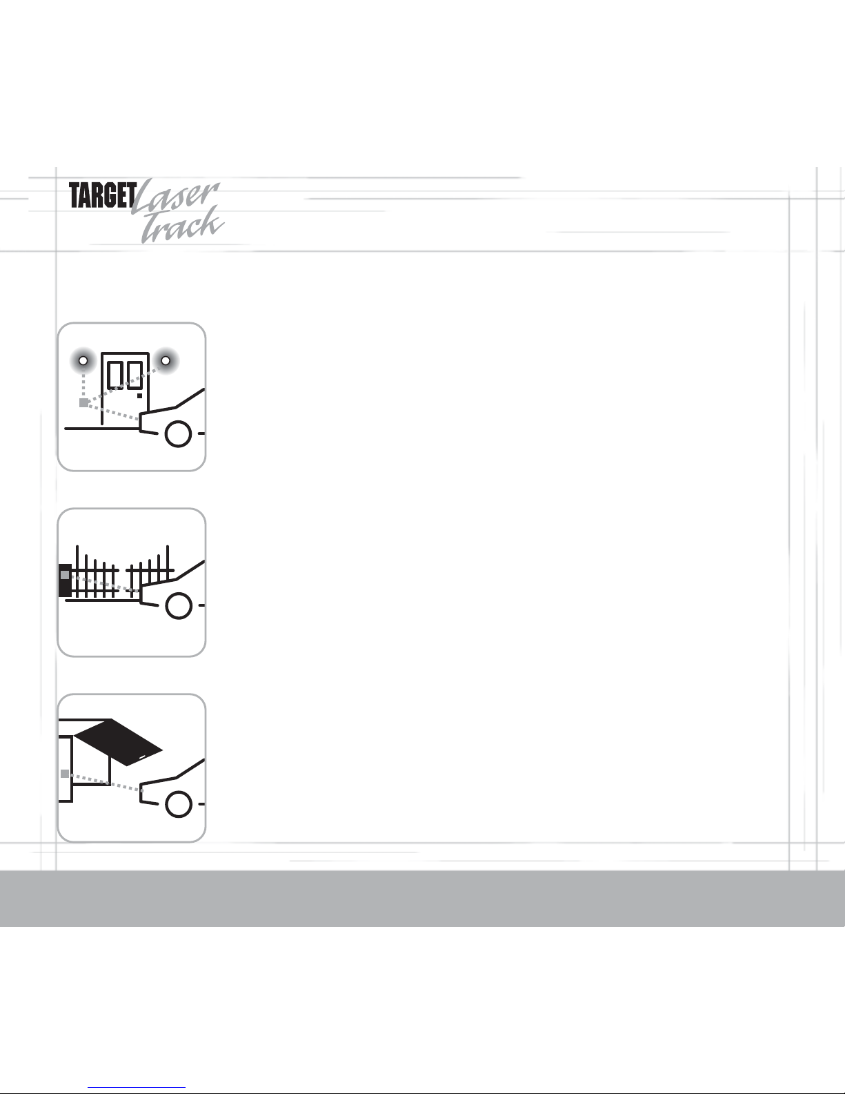
1. Mount the transponder preferably in the middle at the
front of the vehicle (preferably very near to the number
plate). The transponder may also be mounted behind the
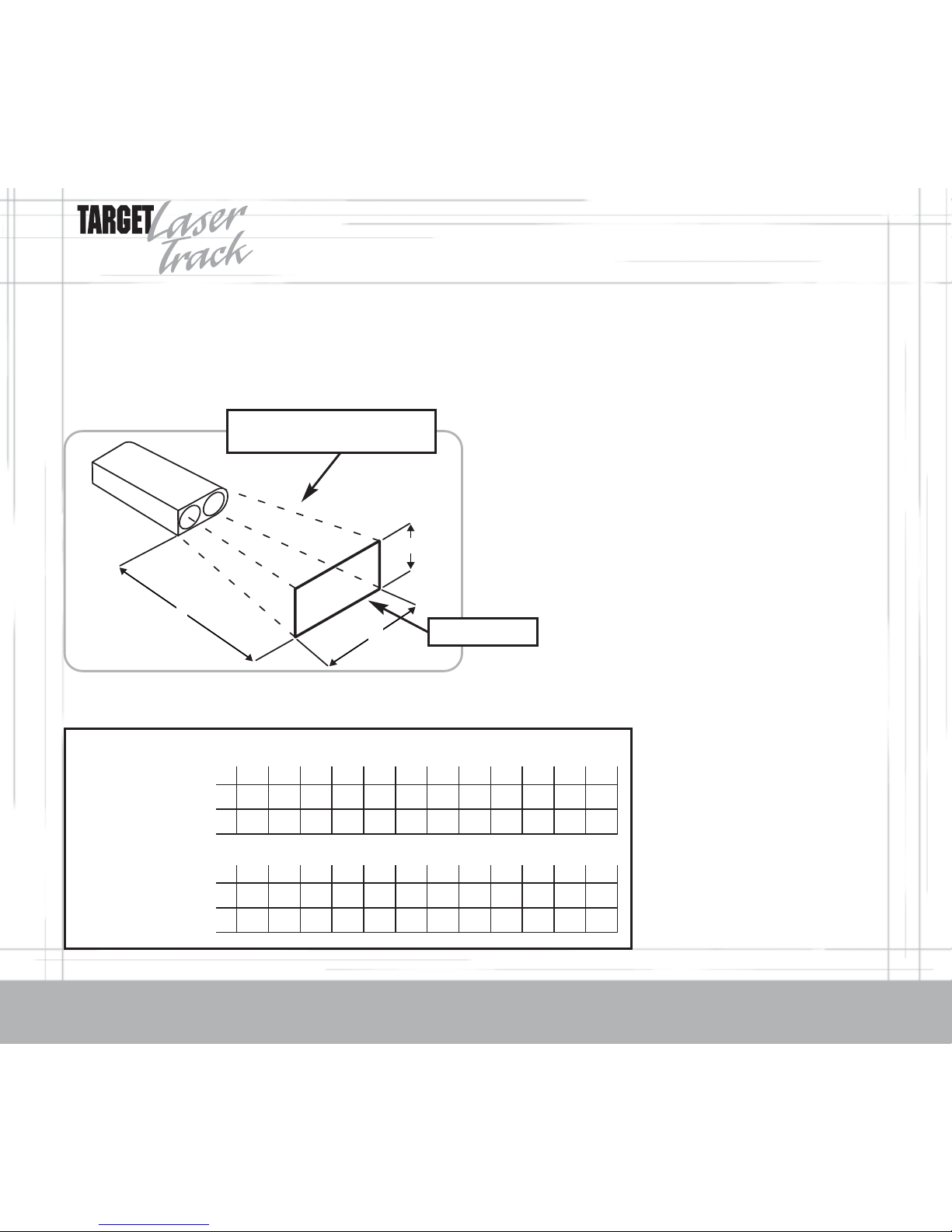
grill. The free passage opening should be larger when the
distance from the transponder to the opening is greater.***
Refer to the calculation table on page 8.
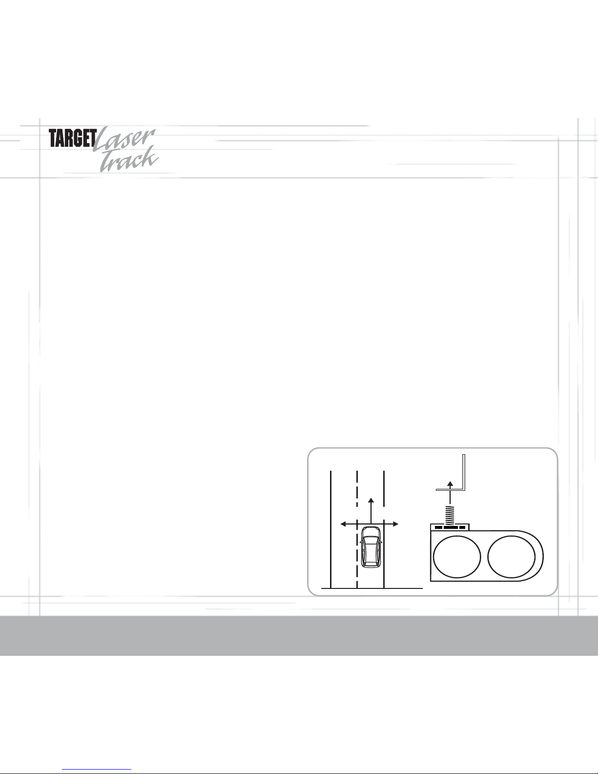
2. Mount the transponder using the tee bolt and
mounting bracket included in the package.
(Refer to Transponder Alignment on page 7.)
3. Ensure the transponder is aligned correctly
(refer to Transponder Alignment on page 7).
4. Lead the transponder cable through the engine com-
partment. Use the cable guides already present when
possible. Do not pull the cable too tightly and do not
kink the cable. Lead the cable through the existing grom-
met to the interior. Connect as indicated in the diagram
on page 88.
ENGLISH
6

CABLE CONNECTION:
LT400 Connect to:
1. Red Switched 12 V from the vehicle (+15).
This is the cable with 12 V as soon as
the vehicle is started. Mount a fuse for
this connection. A switch can be added
to this connection if required.
2. Black Earth. Connect this cable to a good earth
source. Preferably a section of the chassis
of the vehicle.
3. Yellow Connect with the red cable of the Piezo
signal device. Connect the black cable of
the signal device to earth.
4. White Connect with the red cable of the LED.
Connect the black cable of the LED to
earth.
5. Green Do not use. Insulate the cable using
insulating tape.
6. Blue Do not use. Insulate the cable using
insulating tape.
TRANSPONDER ALIGNMENT
The correct alignment of the transponder is very important.
It should be aligned correctly vertically and horizontally.
Vertical alignment: Upwards / Downwards. The transponder
can be adjusted upwards or downwards by turning the angle
iron included in the package. This is the vertical alignment.
Make sure the vehicle is level. Use the water leveller in-
cluded in the package to adjust the vertical position. Place
the water leveller just above the transponder and fasten
the transponder in the correct position.
Horizontal alignment: Left / Right. The transponder can be
turned around itself using the tee bolt. This is the horizon-
tal alignment. The transponder should be placed at a right
angle of the vehicle.
ENGLISH
7
90°90°

CALCULATION TABLE FOR THE
INSTALLATION OF THE TRANSPONDER
Use the table below when mounting the transponder in
the grill or behind a vent hole of the vehicle. Mounting
the TARGET LaserTrack using the parameters below guar-
antees maximum performance.
ENGLISH
8
Measurements are in millimetres
Minimum height H 6 8 9 10 11 13 14 15 16 18 19 20 21
Minimum width W 16 18 21 23 26 28 31 33 36 38 41 43 46
Maximum depth D 0 12 24 36 48 60 72 84 96 108 120 132 144
Minimum height H 23 24 25 26 28 29 30 32 33 34 35 37 38
Minimum width W 48 51 53 56 58 61 63 66 68 71 74 76 79
Maximum depth D 156 168 180 192 204 216 228 240 252 264 276 288 300
H
W
D
Cross-section of laser beam increases
with increase in distance D.
Grill/vent opening

TESTING THE OPERATION
The correct operation of the system can be tested after
the TARGET LT400 has been installed according to the
instructions.
1. Switch the system on by starting the vehicle
(if the switch has been added then it must be
set to ON).
Result: The system emits a short audio signal and the
LED is switched on for 2 seconds. The LT400 will be in
test mode for 10 seconds.
2. Test the operation of the laser receiver using an
infrared remote control device (for audio or video
equipment). Hold the remote control device in
front of the transponder lens (at a distance of
approximately 10 cm) and at the same time press
a button of the remote control device.
Result: The system emits a warning signal and the
LED is switched on.
3. Stop pressing the button of the remote control
device when you are satisfied that the system is
functioning correctly.
Result: After the last received signal the LED will be
switched on for 10 seconds. After the 10 seconds have
elapsed the system will emit two short audio signals.
The LT400 is now in the stand-by mode.
IMPORTANT INFORMATION
FOR ALL USERS
•
Check frequently whether the lens of the transponder
is dirty. The effect of dust and grit on the function-
ing of the system is very limited. Objects that cover
the lens completely, such as leaves or insects, should
be removed at once.
•
Check frequently whether the housing and the lens
of the transponder show signs of damage.
Contact your dealer if the lens is damaged.
•
A dealer should check the tuning of the transponder
periodically (for example, when the vehicle is
serviced).
ENGLISH
9

FAQ ABOUT TARGET LASERTRACK
1. Can other Target LaserTrack users gain access to
my grounds or garage?
No, Target LaserTrack has more than 4.5 thousand
million unique codes. Only vehicles for which the
code has been programmed in the basic transponder
can gain access.
2. Does the Target LaserTrack laser beam damage
the eye?
No, the Target LaserTrack is a Class 1 laser and is,
therefore, completely safe.
3. Can I control other systems or equipment than
those mentioned in the manual using the
Target LaserTrack?
Yes, in principle all electrical systems can be
switched on and off remotely using the Target
LaserTrack. We recommend contacting the dealer
for the system before applying the Target LaserTrack.
4. Does the Target LaserTrack meet all the legal
requirements and can I legally use the system
anywhere?
Yes, the Target LaserTrack meets the highest
European standards for automotive accessories.
Although interference with other equipment such as
laser guns cannot be ruled out, the system may be
used everywhere for the purpose it was developed.
The system may not be used for other purposes than
that for which it was developed by the manufacturer.
5. Is the Target LaserTrack influenced by police laser
guns or other infrared laser systems?
Yes, every laser gun or other laser system that emits
on a frequency of 904 nanometre is recognized by
the Target LaserTrack as an external source of inter-
ference. The Target LaserTrack shall always switch
itself off after a few seconds to prevent mutual
interference.
ENGLISH
10

INSTALLATION OF THE LT425 CONTROL
CIRCUIT BOARD AND THE LT420 BASIC
TRANSPONDER
MOUNTING THE LT420 BASIC TRANSPONDER
1. The LT420 basic transponder is mounted in the same
way as the LT400 car transponder. Ensure that the
transponder is mounted at a location where it can
detect the arriving vehicle. Avoid mounting it behind
bushes or other obstacles.
2. Mount the LT420 at the same height or as near to
it as possible as the LT400 on your vehicle. This is
especially important to guarantee the communication
between the vehicle transponder and basic transpon-
der at a short distance.
3. Make sure the cable is long enough to reach the
location where the control circuit board is mounted.
4. Ensure that the cable cannot be pinched. Especially
when the system is used to open and close gates.
5. Connect the plug of the LT420 to the control circuit
board.
Two LT420 transponders can be connected to the control
circuit board (depending on the actual circumstances).
CONNECTING THE LT 425 CONTROL
CIRCUIT BOARD TO THE GATE OR
GARAGE DOOR
The control circuit board is connected to the garage door
or gate differently depending on the brand and type of
door or gate.
Refer to the garage or gate system dealer for instruc-
tions for the connection of the system to your gate
or door.
The switching off can be delayed by 5 to 120 seconds
when the potentiometer is connected to the control cir-
cuit board. Turn the potentiometer in the direction of the
arrow to increase the delay.
The control circuit board should be placed in a separate
waterproof cabinet if it cannot be placed inside the gate
or garage door switch box.
ENGLISH
11

PROGRAMMING THE
TARGET LASERTRACK
1. Park your vehicle at a few meters distance and in
line with the basic transponder. Make sure that the
LT400 is in stand-by mode.
2. Press the BUTTON-1 or BUTTON-2 button (depending
on the group it is connected to) on the control circuit
board for 2 seconds.
Result: The corresponding LED blinks. LED 10 shall blink
for 10 seconds and it will subsequently start flash-
ing when the code from the LT400 is received.
The code of the vehicle is saved in the memory.
OR
Result: The corresponding led blinks repeatedly for
30 seconds after which it returns to the usual
flashing pattern. This means that the code of
the vehicle has not been received. Check the
position of the vehicle and the basic trans-
ponder and repeat the procedure from step 2
onwards.
A maximum of 50 vehicles can be programmed into the
system in the above manner.
Program the second transponder in manner described
above if you have connected two LT420 transponders
to a single control circuit board.
Important: The car transponder concerned has to be
reset after programming the LT400 car transponder.
The LT400 switches off after a programming cycle to
prevent the gate or garage door to be opened imme-
diately.
DELETING VEHICLES FROM
THE BASIC SYSTEM MEMORY
All the codes saved in the memory of the connected
transponder shall be deleted if you press BUTTON-1
or BUTTON-2 for more than 5 seconds. The LED shall
blink 5 times to confirm it.
The vehicles that should have access should be pro-
grammed into the memory again.
ENGLISH
12

ENGLISH
13
TECHNICAL SPECIFICATIONS
LT400
Type of emitter : Indium Gallium Arsenide laser diode, Class 1
Type of receiver : Infrared photodiode with optical and electronic amplifier
Wave length : 904 nanometre
Unique codes : > 4.500.000.000
Measurements in millimetres : Transponder 75 x 39 x 22 (l x w x h)
Transponder housing : Aluminium, waterproof
Supply voltage : 13.8 volt DC (nominal)
Acoustic signalling : 87 dBA.
Period of transmission after trigger : Maximum 8 seconds, reset time is 60 seconds
Power consumption : 500 mA max.
LT420
Type of receiver : Infrared photodiode with optical and electronic amplifier
Wave length : 904 nanometre
Maximum number of memory slots LT400 : 50
Measurements in millimetres : Transponder 75 x 39 x 22 (l x w x h)
Transponder housing : Aluminium, waterproof
Supply voltage : through the LT425
LT425
Supply voltage : AC / DC 20 – 27 V (max.)
Maximum relay load : 3 A 12 – 250 V AC / DC
Switching delay : min. 5 – max. 120 seconds Variable through a potentiometre
Maximum number of connected LT420 transponders : 2
Power consumption : 300 mA max. (with 2 connected LT420 transponders)

Conditions of Guarantee
1. The manufacturer guarantees the reliability of the
system. The guarantee is valid for a term of 12 months
for what concerns manufacturing and/or material
failure and the following (excluding all other):
- If and when the system is used for the purpose
for which it was designed and is mounted and used
in the correct manner and under circumstances that
can be deemed to be normal, and all this according
to the regulations and/or instructions of the manu-
facturer.
- If and when the buyer has met all his responsibili-
ties and the buyer informs the dealer at once, and
no later than one week, after detecting the failure
or fault and the dealer finds the system in the state
in which the system was at the moment the fault
or failure was discovered.
2. The guarantee is valid if and when the buyer has
filled in the warranty registration form and mailed
it within two weeks of the purchase date.
3. The guarantee is not valid if and when any work
has been or is carried out on the system within
the guarantee period without the prior written
permission of the manufacturer.
4. The guarantee claim will be processed after the
defect system or the part concerned has been
shown to the dealer. The buyer should also provide
the warranty registration form with the stamp of the
dealer and the serial number of the system as well as
the original proof of purchase or cash register slip.
5. To meet the obligations under the guarantee the
manufacturer is only legally entitled and obliged to
deliver or repair the system or parts thereof con-
cerned, at the discretion of the manufacturer.
6. The manufacturer is not bound by the guarantee to
carry out or pay for the disassembling or installing
of the system or parts thereof. Postage and handling
costs are at the expense of the buyer.
7. The manufacturer is never liable for any damage to
persons or goods caused by the malfunction or not
functioning of the system.
8. Only Dutch law is applicable to deliveries of the
system.
ENGLISH
14

ENGLISH
15

ENGLISH
16
This manual suits for next models
2
Table of contents
Other Target Radar Detector manuals