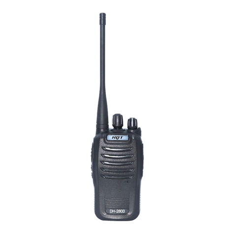
Team Electronic UHF-Handy User manual

Bedienungsanleitung
Operation Manual
Mode d’emploi
Manuale d’istruzione
electronic
UHF-Handy
UHF-Handy
UHF-Handy
Public Mobile Radio &Low Power Device
Manual_UHF-Handy 18.07.2003 16:53 Uhr Seite 1

1
2
3
4
5
4
6
7
8
9
10
electronic
1.) Antenna
2.) Jack earphone / microphone
3.) LCD Screen
4.) Up & Down Key
5.) Confirmation & On/Off Key
6.) Speaker
7.) Mic: Microphone
8.) Volume Key
9.) PTT Key
10.) Call Tone Key CALL
English Page 21 - 36
1.) Antenne
2.) Prise auriculaire / microphone
3.) Affichage LCD
4.) Touche vers le haut et le bas
5.) Touche de confirmation et Marche/Arrêt
6.) Haut-parleur
7.) Mic: Microphone
8.) Touche de volume
9.) Touche PTT
10.) Touche d’appel CALL
Français Page 37 - 53
1.) Antenna
2.) Presa per auriculare / microfono
3.) Indicatore LCD
4.) Tasto crescente e discendente
5.) Tasto di confermazione e Marcia/Arresto
6.) Altoparlante
7.) Mic: Microfono
8.) Tasto di volume
9.) Tasto PTT
10.) Tasto della suoneria CALL
Italiano Pagina 54 - 69
2
UHF-DualTalk
PMR + LPD Radio
1.) Antenne
2.) Buchse Ohrhörer / Mikrofon
3.) LCD-Anzeige
4.) Auf- & Abwärts-Taste
5.) Bestätigungs- & Ein-/Aus-Taste
6.) Lautsprecher
7.) Mic: Mikrofon
8.) Lautstärketaste
9.) PTT-Taste
10.) Ruftontaste CALL
Deutsch Seite 4 - 20
3
Manual_UHF-Handy 18.07.2003 16:53 Uhr Seite 2

Page
Controls & Connectors 2 - 3
LC-Display 22
Set Up 23
1) Inserting the batteries 23
2) Replacing the front panel 23 - 24
3) Switching On/Off: 24
4) LCD illumination 24
5) Key lock function 25
6) Automatic abortion of functions 25
7) Up ▲and Down ▼ keys 25
8) Socket for external ear- & microphone 25 - 26
9) Battery indication 26
10) Power save function 26
11) Receipt tones 26
Operation 27
1) Band and channel selection 27 - 28
2) Channel selection within the actual band 28 - 29
3) Activation of the CTCSS function &
selection of the CTCSS tone 29
4) Volume adjustment 30
5) Squelch adjustment 30
6) Setting of the VOX function 30 - 32
7) Selection of the call melody 32 - 33
8) Monitor function 33
9) Activating of the channel scan function 34
10) Transmitting 35
Additional Information
Safety 35
Service 36
Conformity 36
Frequency tables 71
Accessories 72 - 73
Specifictions are subject to change without any prior notice or obligation.
Service
Von Zeit zu Zeit ist der Zustand der Batterien zu prüfen. Ver-
brauchte Batterien sind sofort aus dem Gerät zu nehmen, da
sie auslaufen und dieses schädigen können. Tauschen Sie
immer den ganzen Satz Batterien aus. Verbrauchte Batteri-
en gehören nicht in den Abfall, sondern sind an geeigneten
Sammeldepots oder beim Fachhändler zurückzugeben, der
Umwelt zuliebe. Das Gerät darf nicht geöffnet werden.
Eigenhändige Reparaturen oder Abgleich sind nicht vorzu-
nehmen, denn jede Veränderung bzw. Fremdabgleich kön-
nen zum Erlöschen der Betriebserlaubnis sowie der Garan-
tie- und Reparaturansprüche führen. Liegt ein Defekt vor,
sollte auf jeden Fall der autorisierte TEAM-Fachhändler oder
TEAM direkt zu kontaktiert werden.
Entsorgung
Bitte werfen Sie Ihr TEAM-Altgerät nicht einfach auf den
Müll, sondern senden Sie Ihr Altgerät bitte portofrei zur fach-
gerechten Entsorgung an TEAM Electronic ein. TEAM Elec-
tronic wird anschließend die fachgerechte und umweltscho-
nende Entsorgung Ihres TEAM Altgeräts für Sie kostenlos
veranlassen. Bitte machen Sie mit - der Umwelt zuliebe.
Konformität
Das Handfunkgerät TEAM UHF-Handy entspricht der
europäischen R&TTE Direktive und hält die europäischen
Telekommunikationsstandards ETSI EN 300 296-1/-2, ETSI
EN 301 489-3/-5, und EN 60950 ein.
Dieses Produkt ist bestimmt für die Inverkehrbringung und
den Betrieb in folgenden Ländern:
Deutschland, Frankreich, Griechenland, Italien, Niederlande,
Österreich und Schweden.
Deutsch
20
Contens English
21
Manual_UHF-Handy 18.07.2003 16:53 Uhr Seite 20

English
22
AAppears if normal PMR status is activated or if
Vox is switched on.
DIndicates the actual condition of the batteries.
FIndicates the selected PMR or LPD channel.
CAppears if key lock function is activated
BIndicates the selected frequency band, i.e. PMR or
LPD.
GIndicates the selected CTCSS Code 1 - 38.
EIndicates receiving signals or for
transmitting mode.
RT
LC-Display
ABCD
EFG
Main Screen
Setting up the TEAM UHF-Handy
1) Inserting the batteries
Turn the unit in that way that the rear panel lies in front of
you. Rotate the belt clip a quarter turn counter-clockwise, so
that the battery compartment lid is accessible now. At the
bottom of the battery compartment lid there is a spring catch.
To open the lid you have to release the interlock. For this end
push it with you thumbnail or fingernail towards the top of the
unit. If it is pushed far enough, it is possible to draw it away
from the unit. Thus you will lift off the lid also.
Now insert 4 alkaline or rechargeable cells of AAA type
( = Micro ) into the battery compartment according to the
polarity signs inside. If you use rechargeable cells we recom-
mend the NiMH type.
To close the battery compartment put the lid onto the com-
partment in that way that the two guide bolts at the top of the
lid grip into the two corresponding guide holes at the top of
the battery compartment. Then shut the battery compartment
by pressing on the lid at the bottom until it locks in.
Finally rotate the belt clip back into its original position.
2) Replacing the front panel
Every unit can be equipped either with a blue or a red front
panel. The front panel is fixed at three points on the unit’s
body. One is located on the top of the unit near the socket for
the external earphone-microphone and the other two ones
directly above the two charging contacts at the bottom.
To detach the actual front panel, release it at first at one of
the two lower fixing points. For this reason press your thumb-
nail at one side into the joint between front panel and the
unit’s body near the charging contact at the bottom. After
having loosened the front panel at this point release it the
English
23
oI
Manual_UHF-Handy 18.07.2003 16:53 Uhr Seite 22

same way also at the other side. Use your other thumb to
prevent an unintentional lock-in of the front panel at the other
side. Now you can lift off the front panel from the unit’s body.
Now place the new front panel onto the unit. Then press
slightly onto the front panel near the socket for the external
earphone-microphone and in the area of the two charging
contacts at the bottom until it locks in. The new front panel
must lie correctly on the unit’s body now.
3) Switching On/Off
Depress the confirmation and On/Off key ( 5 ) for about 1
or 2 seconds to switch the transceiver on. A short receipt
tone sounds from the loudspeaker ( 6 ) and the display illu-
mination lights up in blue. In a short self test the graphic dis-
play ( 3 ) shows all points. Now the unit is either in PMR
reception mode or in LPD reception mode. The display will
show the main screen which indicates also the actual band.
To switch the unit off depress the confirmation and On/Off
key ( 5 ) again for about 1 or 2 seconds. The loudspeaker
gives a short tone and all symbols disappear from the dis-
play. The last settings remain memorised, even if the batte-
ries are removed.
Note: The On/Off operation of the confirmation and On/Off
key ( 5 ) is disabled when it is used for confirmation. This
factory setting has been made to avoid an unwanted swit-
ching Off of the unit. The disabling of the On/Off function will
be cancelled after the key ( 5 ) is released once for a short
time.
4) LCD illumination
The LC display backlight is switched on at every pressure on
any key, and it will be automatically shut off 8 seconds after
the last key entry.
5) Key lock function
The key lock function is activated from the main screen. The
unit can be either in PMR mode or in LPD mode. Depress
and hold the confirmation key ( 5 ). While you hold this key,
press also the Up key ▲( 4 ). Then two short confirmation
tones sound from the speaker ( 6 ), and the key symbol
( position C ) appears in the display. Now all keys except
the PTT key ( 9 ) are ignored. The speaker gives two short
tones at every pressure on any locked key, except the con-
firmation key ( 5 ).
To stop the key lock function depress and hold the confirma-
tion key ( 5 ). While you hold this key, press also the Up key
▲( 4 ). Then one single short confirmation tone sounds from
the speaker, and the key symbol disappears from the display.
Now all keys are unlocked again.
6) Automatic abortion of functions
If you select a function in the main menu, you have to insert
all necessary entries within 5 seconds, otherwise the func-
tion will be aborted and not executed. Instead the display
returns to the main screen.
7) Up ▲and Down ▼keys
If you depress briefly the keys Up ▲and Down ▼( 4 ), the
corresponding values ( volume, channel, etc. ) are changed
for one step up or down. If you hold these keys for 1 or 2
seconds, the values change quickly into the corresponding
direction. Some values run in a ring like system, others
remain constantly after they have reached the highest or
lowest value. In this case you will hear from the speaker a tri-
ple confirmation tone.
8) Socket for external earphone-microphone
The socket ( 2 ) ( ø 2.5 mm ) on the top side of the unit can
be used to connect an external earphone-microphone, i.e.
English English
24 25
Manual_UHF-Handy 18.07.2003 16:53 Uhr Seite 24

Operation of the TEAM UHF-Handy
The TEAM UHF-Handy offers you the possibility to commu-
nicate in a band of your choice out of two radio bands in the
70-cm-band ( UHF ). One band is the PMR band ( 446.00625
MHz – 446.09375 MHz ) and the other one the LPD band
( 433.075 MHz – 434.775 MHz ). The TX output power is
automatically matched to the allowed maximum value of the
actual selected band. This is 500 mW radiated TX output
power in PMR operation and 10 mW radiated TX output
power in LPD operation. The actual selected band is indica-
ted by the letter on the upper left corner of the main screen.
The Pmeans PMR mode and the Lmeans LPD mode.
If the unit receives an audible signal of a station the symbol
R( E ) appears in the lower left corner of the main screen.
The following functions have to be selected from the main
screen ( main menu ).
1) Band and channel selection
To select another radio band depress out of the keys ( 4 )
Down ▼7 times or Up ▲once. The display shows the writ-
ing CH. Then depress briefly the confirmation and On/Off key
( 5 ). Then the display shows the writing . On the left
side of the writing CH you see an arrow, which can be moved
with the help of the Up/Down keys ( 4 ) either to the left side
of the writing Band or back to the left side of the writing CH.
For the activation of the band selection put the arrow to the
left side of the writing Band and then depress the confirma-
tion key ( 5 ). Then the display shows the writings or
, depending on which one of the two bands the actual
band is. With the help of the keys ( 4 ) you can toggle bet-
ween both indications. Then, depress the confirmation key
( 5 ) for the final selection of the indicated band. Now the dis-
English English
27
TEAM ORM-MS. While the socket is used the internal spea-
ker ( 6 ) and the internal microphone Mic ( 7 ) are switched
off.
9) Battery indication
The battery symbol appears at the main screen at the
position D. In case of completely charged batteries it is com-
pletely filled-in. At 4.9 V supply voltage one third of the filling
disappears, at 4.6 V one other third, and at 4.1 V there is
only the frame remaining.At 3.8 V the frame starts to blink at
last. Now it is time to change or charge the batteries or
accus, otherwise errors of functions and displayed informati-
on may occur. The current consumption in transmit mode
amounts to 270 mA ( PMR mode ), 100 mA ( LPD mode ), in
reception mode with closed squelch 40 mA and in power
save mode 15 mA.
10) Power save function
The power save mode is only active in reception mode. If the
squelch is not opened by a signal for at least 20 seconds,
and if there is no key entry during this time, the unit falls into
the power down mode. In this mode the receive section is
supplied only periodically for a short time, so that the current
consumption goes down from 40 mA to 15 mA. On receiving
of a signal or pressing any key the power save mode swit-
ches itself off again.
11) Receipt tones
If a signal is found on the actual channel in PMR or LPD ope-
ration the receipt tones are switched off. Otherwise every
pressure of a key is indicated by a short tone.
26
Manual_UHF-Handy 18.07.2003 16:53 Uhr Seite 26

play shows or , depending on which one of the two
bands you selected before. The number 8 stands for the
number of the actual channel of the actual band. By the help
of the Up/Down keys ( 4 ) the channels 1 to 8 of the PMR
band or the channels 1 to 69 of the LPD band can be chan-
ged in the wanted direction in a ring like system. Press the
confirmation key ( 5 ) to select the desired channel, and the
display will return to the main screen. Now the channel num-
ber appears at the position ( F ) and the frequency band at
the position ( B ). The symbol Pmeans PMR mode and the
Lmeans LPD mode.
The channel number of the not selected band remains sto-
red.
2) Channel selection within the actual band
To select another channel within the actual band depress out
of the keys ( 4 ) Down ▼7 times or Up ▲once. The display
shows the writing CH. Then depress briefly the confirmation
and On/Off key ( 5 ). Then the display shows the writings
. On the left side of the writing CH you see an arrow,
which can be moved with the help of the Up/Down keys ( 4 )
either to the left side of the writing Band or back to the left
side of the writing CH. For the activation of the channel sel-
ection put the arrow on the left side of the writing CH and
then depress the confirmation key ( 5 ). Then the display
shows the writings or , depending on which one of
the two bands the actual band is. The number 8 stands for
the number of the actual channel of the actual band. By the
help of the Up/Down keys ( 4 ) the channels 1 to 8 of the
PMR band or the channels 1 to 69 of the LPD band can be
changed in the wanted direction in a ring like system. Press
the confirmation key ( 5 ) to select the desired channel, and
the display will return to the main screen. The channel num-
ber appears at the position ( F ). The actual frequency band
( Position B ) and the channel number of the not selected
band remain unchanged.
3) Activating the CTCSS function and selecting a CTCSS tone
The CTCSS function serves to suppress signals of unwanted
stations on the actual channel. If this function is active the
unit works as follows:
The other station is only audible in the speaker, if it adds to
its modulation signal a certain tone in the frequency range
from 67 Hz to 250 Hz with low level. In transmit mode the unit
adds itself to its modulation signal a tone of the same fre-
quency so that the muting device of the counter station can
open also. If the function is inactive you can hear every sta-
tion on the channel, and in transmit mode no tone is added
to the modulation signal.
To select the CTCSS function depress out of the keys ( 4 )
Down ▼6 times or Up ▲2 times. The display shows the writ-
ing .Then depress briefly the confirmation and On/Off
key ( 5 ). Then the display shows the writing , where the
“22“ stands for the actual CTCSS tone code. By the help of
the Up/Down keys ( 4 ) the code numbers 0 to 38 can be
changed in the wanted direction in a ring like system. Press
the confirmation key ( 5 ) to select the desired code number,
and the display will return to the main screen. If the code
number is different from zero, it will be visible in the main
screen at the position ( G ). That means that the CTCSS fun-
ction has been activated with the CTCSS tone corresponding
to the code number.
If the selected code is “00“, there will be no code number visi-
ble in the lower right corner ( position G ) of the main screen.
That means that the CTCSS function is switched off now.
In the table in the annex you find the corresponding CTCSS
frequencies to the code numbers.
English
28
English
29
Code Code
22
Manual_UHF-Handy 18.07.2003 16:53 Uhr Seite 28

time, within which the sound level at the microphone remains
below this intensity value, the radio switches automatically
back to receive mode. During reception of an incoming sig-
nal the VOX function is inhibited. Thus you can communica-
te without the necessity of having a hand at the unit.
To activate the VOX function depress out of the keys ( 4 )
Down ▼4 times or Up ▲4 times. The display shows the writ-
ing . Then depress briefly the confirmation key ( 5 ).
Then the display shows . Below the writing “on“ you see
a microphone symbol. On the left side of the writing “on“ you
see an arrow, which can be moved with the help of the
Up/Down keys ( 4 ) either to the left side of the microphone
symbol or back to the left side of the writing “on“. For the final
activation of the VOX function put the arrow on the left side
of the writing “on“ and then depress the confirmation key ( 5 ).
After this entry, the display returns to the main screen. On
the position of the transceiver symbol ( A ) you see the
microphone symbol now. This indicates that the VOX fun-
ction is active now. If you talk loud enough into the micro-
phone Mic ( 7 ), a short tone comes from the speaker and in
the display you see at the position ( E ) the symbol T, indi-
cating transmit mode. 1 to 2 seconds after you have finished
your message the unit switches back to receive mode, which
is indicated by two short tones and the disappearance of the
symbol T.
To deactivate the VOX function depress out of the keys ( 4 )
Down ▼4 times or Up ▲4 times. The display shows the writ-
ing . Then depress briefly the confirmation key ( 5 ).
Then the display shows . On the left side of the writ-
ing “off“ you see an arrow, which can be moved with the help
of the Up/Down keys ( 4 ) either to the left side of the micro-
phone symbol or back to the left side of the writing “off“. For
the deactivation of the VOX function put the arrow on the
4) Volume adjustment
To adjust the volume level of the reproduction of incoming
signals depress the volume key ( 8 ). The display shows
a loudspeaker symbol with one or several points or bars
. The number of those points or bars shows the actual
setting of the volume adjustment. By the help of the
Up/Down keys ( 4 ) this setting can be changed and watched
in the display. The volume level of the tones depends from
the actual setting of the volume adjustment. At the highest or
lowest value you hear a triple confirmation tone. Press the
confirmation key ( 5 ) or the volume key ( 8 ) to select
the desired setting of the volume adjustment, and the display
will return to the main screen.
5) Squelch adjustment
To adjust the threshold level of the noise suppression
( squelch ) in reception mode depress out of the keys ( 4 )
Down ▼5 times or Up ▲3 times. The display shows the writ-
ing . Then depress briefly the confirmation key ( 5 ). Then
the display shows the writing SQ with one or several points
or bars . The number of those points or bars shows the
actual setting of the squelch sensitivity level. The more
points or bars appear, the lower the level can be for opening
the squelch. By the help of the Up/Down keys ( 4 ) this set-
ting can be changed and watched in the display. At the hig-
hest or lowest value you hear a triple confirmation tone.
Press the confirmation key ( 5 ) to select the desired setting
of the squelch sensitivity level, and the display will return to
the main screen.
6) Activating and setting the VOX function
If the VOX function ( = voice activated transmission ) is
active, the transmitter is switched on if the sound level at the
microphone Mic ( 7 ) exceeds a certain intensity. After a certain
English
30
English
31
VOX
VOX
SQ
Manual_UHF-Handy 18.07.2003 16:53 Uhr Seite 30

return to the main screen at once. If you don’t press any key
for 1 or 2 seconds after a selection the call melody will be
played in full length in the speaker and selected also. Then
the display will return to the main screen.
8) Monitor function
In normal mode the unit is always in reception mode. This
would cause a disturbing noise on free channels. Therefore
the unit is equipped with a noise suppression circuit
( squelch ) for reception mode. It cuts off the disturbing noise,
which the receiver produces on free channels, and lets pass
only the speech signals of a counter station to the speaker.
While the squelch is open display shows the symbol Rat the
position ( E ). In case of very weak signals it may occur, that
the squelch remains closed. If you want to make also these
signals audible, you can inhibit the squelch ( monitor function ).
To this end depress out of the keys ( 4 ) Down ▼2 times or
Up ▲6 times. The display shows the writing . Then,
depress briefly the confirmation key ( 5 ). Now the squelch is
always open and you can hear a noise on free channels. In
the display you can see , where the “8“ stands for the
actual channel number in the actual band. This is the sub-
screen for monitor operation. In this condition you can only
adjust the volume level setting ( Para 4 ) or the squelch sen-
sitivity setting ( Para 5 ). To adjust the volume level of the
reproduction of incoming signals depress the volume key ( 8 ).
See paragraph 4 for the further instructions. To adjust the
squelch sensitivity setting for incoming signals depress out of
the keys ( 4 ) Down ▼once or Up ▲once. See paragraph 5
for the further instructions. To reactivate the squelch,
depress in the sub-screen for monitor operation the confir-
mation key ( 5 ), and the display will return to the normal
main screen.
left side of the writing “off“ and then depress the confirmati-
on key ( 5 ). After this entry the display returns to the main
screen. On the position of the microphone symbol ( A )
you see the transceiver symbol again. This indicates that
the VOX function is no longer active.
The adjustment of the threshold of the sound level at which
the transmitter starts to work, can be executed at inactive or
active VOX function. To this end depress out of the keys ( 4 )
Down ▼4 times or Up ▲4 times. The display shows the writ-
ing . Then, depress briefly the confirmation key ( 5 ).
Then, the display shows or . Now put the arrow on
the left side of the microphone symbol below and then
depress the confirmation key ( 5 ). Then the display shows
, the microphone symbol with one or several points or
bars. The number of those points or bars shows the actual
setting of the VOX sound level threshold. The more points or
bars appear, the louder you have to speak to start the trans-
mission. By the help of the Up/Down keys ( 4 ) this setting
can be changed and watched in the display. At the highest or
lowest value you hear a triple confirmation tone. Press the
confirmation key ( 5 ) to select the desired setting of the
sound level threshold, and the display will return to the main
screen.
7) Selection of the call melody
To select a call melody depress out of the keys ( 4 ) Down ▼
3 times or Up ▲5 times. The display shows the writing
Tone. Then depress briefly the confirmation and On/Off key
( 5 ). Then the display shows , a music note symbol
and a digit. The digit stands for the number of the actual call
melody. By the help of the Up/Down keys ( 4 ) the call melo-
dy numbers can be changed from 1 to 8 in the wanted direc-
tion in a ring like system. By pressing the confirmation key
( 5 ) you select the desired call melody, and the display will
English
32
English
33
MON on?
VOX
MON
8
Manual_UHF-Handy 18.07.2003 16:53 Uhr Seite 32

10) Transmitting
For speech transmission depress and hold the transmit key
PTT ( 9 ) on the left side of the unit. In the display appears
the symbol Tat the position ( E ). If the channel scan func-
tion had been active, it would be terminated now. The sensi-
tivity of the built-in microphone Mic ( 7 ) has been set to give
good results speaking normally at a distance of 2 inches.
Speaking too loudly will cause distortions and make the sig-
nal difficult to understand. On completion of the transmission
release the transmit key PTT ( 9 ) and the unit will revert to
receiving mode and in the display the Twill disappear.
For call melody transmission on the actual channel depress
the call tone key CALL ( 10 ) above the PTT key. The unit
transmits the actual call melody in full length, no matter how
long you press the call tone key CALL ( 10 ). It is only audible
at the counter station. In this period the display shows the
symbol T at the position ( E ). Speech transmission is
impossible now.After finishing transmission the unit switches
back to receiving mode with a short melody in the speaker
( 6 ) and in the display the symbol Twill disappear.
Safety
The unit radiates in transmit mode RF energy. To reduce the
exposure at the lowest possible value, and to benefit as
much as possible of the features of the unit, you should take
into account the following advice:
In transmission mode keep the unit in a vertical position at a
distance of 2 to 3 inches from your face. Keep the antenna
( 1 ) at a distance of at least 1 inch away from your head and
your body. If you carry the unit on your body and if the unit is
in transmit mode, make sure that the antenna ( 1 ) is kept at
a distance of at least 1 inch away from your body.
9) Activating of the channel scan function
In channel scan mode the unit looks for occupied channels
of the actual band, i.e. channels on which the squelch opens.
After having found one, it examines also, whether the demo-
dulated reception signal contains a CTCSS tone. In this case
it identifies its corresponding code number and shows it in
the display at the position ( G ).
To activate the scan function depress out of the keys ( 4 )
Down ▼once or Up ▲7 times. The display shows the writ-
ing . Then, depress briefly the confirmation key ( 5 ).
Then the display shows . On the left side of the writ-
ing “UP“ you see an arrow, which can be moved with the help
of the Up/Down keys ( 4 ) either to the left side of the writing
“DOWN“ or back to the left side of the writing “UP“. For the
final activation of the channel scan function put the arrow to
one of the both writings and then depress the confirmation
key ( 5 ). The display returns to the main screen, but without
an eventually adjusted CTCSS code number. According to
the chosen direction the channel scan starts stepping
upwards or downwards. The unit stops on every occupied
channel for 10 seconds and shows the symbol Rin this period
at the position ( E ). If there is in the demodulated signal also
a CTCSS tone, it will show also the corresponding CTCSS
code number at the position ( G ). After the 10 seconds have
passed by or after the signal has dropped below the squelch
threshold the channel scan function continues searching. By
pressing the confirmation key ( 5 ) the channel scan function
is terminated and the unit remains on the actual channel.
The display shows the main screen. If the unit was on an
occupied channel where a CTCSS coded station has been
making a transmission, the unit will take over this CTCSS
code. If the station has been sending without a CTCSS code
or the channel has been free, the unit will keep the CTCSS
setting which was active before starting the channel scan.
English
34
English
35
Scan on? UP
DOWN
▼
Manual_UHF-Handy 18.07.2003 16:53 Uhr Seite 34

Service
The condition of the batteries must be tested from time to
time. Worn out batteries must be removed from the unit
immediately. They can leak and damage the device. The bat-
teries should always be replaced as a complete set. Worn
out batteries do not belong in the waste bin, but must be
returned to a suitable collecting depot or to a special dealer,
for the sake of the environment. There are no user adjusta-
ble or user serviceable parts inside the radio. The casing
must not be opened. Independent repairs or adjustments
must not be carried out, since each modification or unautho-
rised intervention will immediately cancel all and any gua-
rantee or repair claims, they are also likely to result in non-
conformity to ETS regulations which will render the set to
become illegal. In the event a defect becoming apparent,
contact a properly equipped and authorised TEAM dealer or
TEAM directly.
Conformity
The transceiver TEAM UHF-Handy complies with the rules of
the European Directive R&TTE and meets the European Tel-
ecommunication Standards ETSI EN 300 296-1/-2, ETSI EN
301 489-3/-5, and EN 60950.
This product is meant for distribution and sale in the following
European countries:
Austria, France, Germany, Greece, Italy, The Netherlands,
Sweden.
English
36
page
Eléments de commande et connecteurs 2 - 3
Afficheur LCD 38
Mise en service 39
1) Insertion des piles 39
2) Changement de capotage avant 39 - 40
3) Mettre en marche / hors circuit 40 - 41
4) Illumination du afficheur LCD 41
5) Verrouillage du clavier 41
6) Terminaison automatique des commandes 41 - 42
7) Touches vers le haut ▲et vers le bas ▼42
8) Prise pour un microphone auriculaire 42
9) Symbole de pile 42
10) Opération économique 43
11) Tons d’acquittement 43
Le fonctionnement du TEAM UHF-Handy 43
1) Sélection de la bande 44
2) Sélection de canaux 45
3) Activation de la fonction CTCSS
et sélection du ton CTCSS 45 - 46
4) Ajustement du volume 46 - 47
5) Ajustement de la suppression de bruit 47
6) Activation et ajustement VOX 47 - 49
7) Sélection de la mélodie d’appel 49 - 50
8) Suspension de la suppression de bruit 50 - 51
9) Ajustement de la recherche des canaux 51 - 52
10) Emettre 52
Informationes additionelles
Sécurité 53
Service 53
Conformité 53
Tableau de fréquence 71
Accessoires 72 - 73
Contenu Français
37
Manual_UHF-Handy 18.07.2003 16:53 Uhr Seite 36

TEAM UHF-Handy
for sale and use in :
• Austria • France • Germany • Greece
• Italy • Netherlands • Sweden
!
Nachdruck oder Vervielfältigung auch Auszugsweise nur mit
ausdrücklicher Genehmigung von TEAM Electronic GmbH.
electronic
TEAM Electronic GmbH
Bolongarostrasse 88
D-65929 Frankfurt / Main
Telefon 069 / 300 950 0
Fax 069 / 31 43 82
eMail [email protected]
Home Page www.team-electronic.de
Manual_UHF-Handy 18.07.2003 16:53 Uhr Seite 74
Table of contents

