TechniSat TechniLAN 4/4 aktiv User manual

DE
EN
MONT_TechniLAN_4_4_aktiv_DE_EN.doc 04.09.2012 09:51 Seite 1
Montageanleitung / Installation Manual
TechniSat
TechniLAN 4/4 aktiv
www.technisat.de
Artikel-Nr.: 0000/3637

2
DE
MONT
_
TechniLAN
_
4
_
4
_
aktiv
_
DE
_
EN.doc 04.09.2012 09:51 Seite 2
Inhalt
1Funktionsweise und Verwendungszweck.................................................................................................... 2
2Sicherheitshinweise............................................................................................................................................. 3
3Das TechniLAN-Netzwerk.................................................................................................................................. 4
3.1 Allgemeines ........................................................................................................................................................ 4
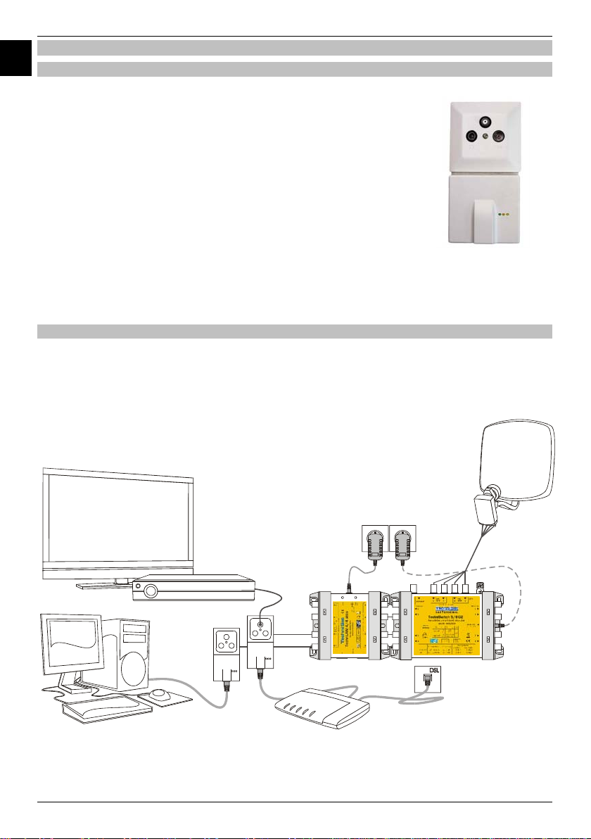
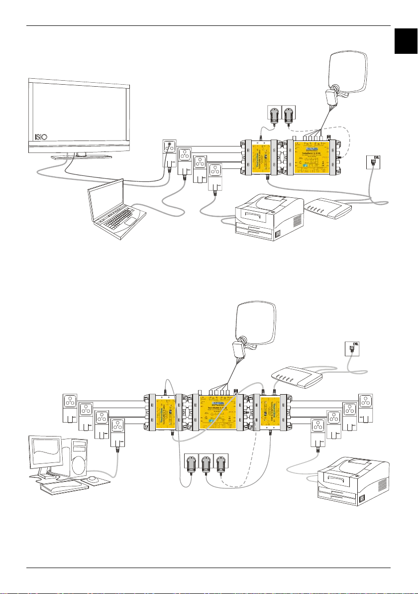
3.2 Installationsbeispiele....................................................................................................................................... 4
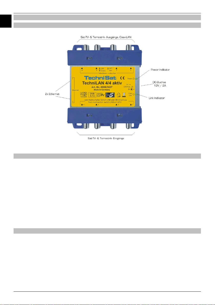
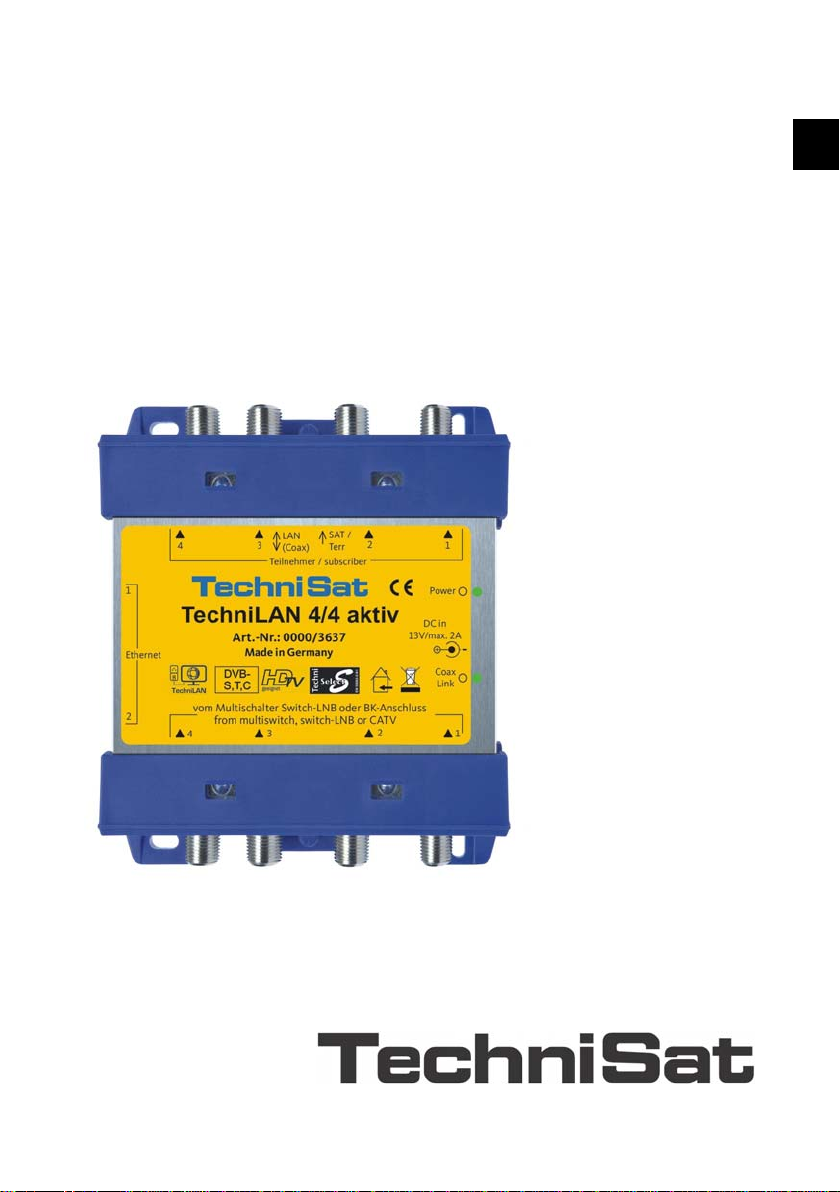
4Der TechniLAN 4/4 aktiv ................................................................................................................................. 6
4.1 Das Gerät............................................................................................................................................................ 6
4.2 Anzeigen und Indikatoren ............................................................................................................................. 6
4.3 Stromversorgung............................................................................................................................................. 6
5Montage und Inbetriebnahme......................................................................................................................... 7
6Technische Daten................................................................................................................................................. 7
7Fehlersuchhilfen .................................................................................................................................................... 8
1Funktionsweise und Verwendungszweck
Mit den TechniLAN-Komponenten erweitern Sie ihr bestehendes Koaxialkabelnetz auf einfache
Art und Weise zu einem Heimnetzwerk, über das elektronische Geräte mit Ethernetanschluss
miteinander kommunizieren können und das ohne Bohren, Kabelverlegung oder Funk.
Zur Erweiterung einer bestehenden Sat-Verteilanlage, benötigen Sie lediglich eine TechniLAN-
Einschleuseweiche, z.B. den TechniLAN 4/4 aktiv, die hinter einem vorhandenen Multischalter in
die Teilnehmerausgänge integriert wird und tauschen die vorhandenen Sat-Antennensteckdosen
gegen TechniLAN-Teilnehmerdosen aus.
Zusammen mit den TechniLAN-Teilnehmerdosen ist der TechniLAN 4/4 aktiv in der Lage, in
bestehenden sternförmigen Verteilnetzen für Satellitenfernsehen eine Netzwerkfunktionalität zu
ermöglichen.
Das TechniLAN-System kann mit allen aktuellen TechniSat Multischalter-Serien eingesetzt
werden, gleich ob diese kaskadiert oder nur in der Grundeinheit verbaut wurden. Das heißt, dass
Sie jede Sat-Verteilung mit TechniSwitch-, TechniSystem-, GigaSwitch-, GigaSystem- und GigaSet-
Multischaltern an bis zu vier TV-Dosen pro eingesetztem TechniLAN 4/4 aktiv zusätzlich für ein
Heimnetzwerk nutzen können.
Auch in BK-Hausverteilanlagen mit Sternverteilstruktur ist der Einsatz möglich.
Internetfähige TV-Geräte und Netzwerkkomponenten wie PCs, NAS-Server, Drucker oder DSL-
Router lassen sich mit TechniLAN so problemlos miteinander vernetzen.
Mit ca. 200 Mbit/s Datenrate sind die resultierenden Netzwerkverbindungen auch für
anspruchsvolle HD-Videostreams völlig ausreichend1. Damit steht selbstverständlich auch für
Internet-Radio und Musikangebote, Bildergalerien und die allgemeine Internetnutzung in jedem Fall
genügend Bandbreite zur Verfügung.
Durch die Nutzung der abgeschirmten, üblicherweise unter Putz verlegten TV-Kabel, entsteht
keine zusätzliche elektromagnetische Strahlung oder Abhörgefahr wie bei Funknetzwerken
(WLAN). Im Gegensatz zu WLAN sind der Festverkabelung auch Störungen der Netzwerk-
verbindung im 2,4 GHz-Band fremd, wie z. B. durch Funktelefone, Bluetooth, Funknetze oder RC-
Fernsteuertechnik.
1vorausgesetzt, die Internetverbindung verfügt über die für Videonutzungen notwendigen 3 Mbit/s

3
DE
MONT
_
TechniLAN
_
4
_
4
_
aktiv
_
DE
_
EN.doc 04.09.2012 09:51 Seite 3
2Sicherheitshinweise
Zu Ihrem Schutz sollten Sie die Sicherheitshinweise vor der Montage sorgfältig durchlesen. Der
Hersteller übernimmt keine Haftung für Schäden, die durch unsachgemäße Handhabung und
durch Nichteinhaltung der Sicherheitsbestimmungen entstanden sind.
•Die Komponenten sind in trockenen Räumen auf ebener, schwer entflammbarer Fläche zu
montieren.
•Bauen Sie die Geräte nicht in die Dachisolation ein. Achten Sie auch darauf, dass das Netzteil
von Luft umgeben ist.
•Installieren Sie die Anlage im stromlosen Zustand.
•Die Antennenanlage ist zu erden.
•Die Antennenanlage muss den Bestimmungen entsprechend gegen Blitzschlag geschützt
sein.
•Die entsprechenden Europanormen und VDE-Bestimmungen zur Gewährleistung der
elektrischen Sicherheit müssen berücksichtigt werden.
•Nationale genehmigungsrechtliche Regelungen für Rundfunkempfangsanlagen sind zu
beachten.
•Öffnen Sie niemals das Gerät.
Ein eventuell notwendiger Eingriff sollte nur von geschultem Personal ausgeführt werden. In
folgenden Fällen sollten Sie das Gerät vom Netz trennen und einen Fachmann um Hilfe bitten:
•das Gerät war Feuchtigkeit ausgesetzt bzw. Flüssigkeit ist eingedrungen,
•bei Fehlfunktionen,
•bei starken äußeren Beschädigungen.

4
DE
MONT
_
TechniLAN
_
4
_
4
_
aktiv
_
DE
_
EN.doc 04.09.2012 09:51 Seite 4
3Das TechniLAN-Netzwerk
3.1 Allgemeines
Die Netzwerkkommunikation über das Koaxialkabel basiert auf dem
HomePlug-AV-Standard, mit dem Datenraten bis zu 200 Mbit/s
erzielt werden können.
Ein solches Netzwerk besteht aus dem TechniLAN 4/4 aktiv und bis
zu vier TechniLAN-Teilnehmerdosen (Art.-Nr. 0000/3639).
Um größere Netzwerke zu realisieren, ist es möglich, mehrere
TechniLAN 4/4 aktiv per Ethernet miteinander zu verbinden.
An die Ethernetbuchsen der TechniLAN-Teilnehmerdosen und des
TechniLAN 4/4 aktiv können die zu vernetzenden Endgeräte wie
Computer, Drucker, DSL-Modems und auch die Smart-TVs und
Digitalreceiver der ISIO-Familie angeschlossen werden.
Es handelt sich hierbei um ein Peer-to-Peer-Netzwerk, bei dem alle
Ethernet-Anschlüsse, auch die des TechniLAN 4/4 aktiv,
gleichberechtigt sind.
3.2 Installationsbeispiele
Die folgenden Beispiele sollen zeigen, wie Netzwerke mit dem TechniLAN 4/4 aktiv aufgebaut
sein können. Empfangsgeräte für das Satellitenfernsehen sind daher nur in geringer Zahl
abgebildet.
Bild 2: Installationsbeispiel, DSL-Modem (Internetverbindung) an einer TechniLAN-Dose angeschlossen
Bild 1: TechniLAN-Dose

5
DE
MONT
_
TechniLAN
_
4
_
4
_
aktiv
_
DE
_
EN.doc 04.09.2012 09:51 Seite 5
Bild 3: Installationsbeispiel, DSL-Modem (Internetverbindung) am TechniLAN 4/4 aktiv angeschlossen
Bild 4: Installationsbeispiel, zwei TechniLAN 4/4 aktiv zu einem Netzwerk zusammengeschaltet

6
DE
MONT
_
TechniLAN
_
4
_
4
_
aktiv
_
DE
_
EN.doc 04.09.2012 09:51 Seite 6
4Der TechniLAN 4/4 aktiv
4.1 Das Gerät
Bild 5: TechniLAN 4/4 aktiv
4.2 Anzeigen und Indikatoren
Power-Indikator: leuchtet grün, sobald das Gerät mit Strom versorgt wird.
Link-Indikator: blinkt bei vorhandener Netzwerkverbindung,
zeigt die Qualität der Datenübertragung über das Koaxialkabel an.
•grün: gute Übertragungsqualität
•orange: ausreichende Übertragungsqualität
•rot: schlechte Übertragungsqualität
•leuchtet nicht: keine Verbindung
Netzwerk-LEDs (an den Ethernetbuchsen):
•grün: verwendete Datenrate des Ports: an … 100Mbit/s; aus … 10Mbit/s
•gelb: blinkt bei vorhandener Netzwerkverbindung
4.3 Stromversorgung
Über das 13V-Steckernetzteil des TechniLAN 4/4 aktiv werden alle TechniLAN-Teilnehmerdosen
gespeist. Gibt ein an der Dose angeschlossener Receiver eine höhere Spannung aus, z.B. 18 V
für die horizontale Polarisation, übernimmt dieser die Spannungsversorgung der Teilnehmerdose,
an der er angeschlossen ist. Die Receiverspannung wird auch zum Multischalter bzw. LNB
durchgeleitet, damit auf die vom Receiver gewünschte Empfangsebene geschaltet werden kann.
Der TechniLAN 4/4 aktiv ist so konzipiert, dass er die Spannungsversorgung des Multischalters
und des LNBs übernehmen kann. Besonders in netzteillosen Anlagen, wie sie zum Beispiel mit
dem TechniSwitch 5/8 möglich sind, ist darauf zu achten, dass der Maximalstrom des
Steckernetzteils nicht überschritten wird.

7
DE
MONT
_
TechniLAN
_
4
_
4
_
aktiv
_
DE
_
EN.doc 04.09.2012 09:51 Seite 7
Der maximale Stromverbrauch kann durch folgende Formel abgeschätzt werden:
Vertmax mA400mA350 InI
+
+
⋅
=
nist hierbei die Anzahl der angeschlossenen TechniLAN-Dosen. Hierbei wird davon ausgegangen
das unter ungünstigen Bedingungen, z.B. bei langen Koaxialkabeln, der Stromverbrauch der
Dosen bei 350 mA und der des TechniLAN 4/4 aktiv bei 400 mA liegt.
IVert ist der Strom, der in die Verteilanlage (Multischalter und LNB) gespeist wird. Dieser liegt in
der Regel bei maximal 400 mA.
Gegebenenfalls ist ein Steckernetzteil an den Multischalter anzuschließen, das dann die
Spannungsversorgung der Verteilanlage übernimmt. Dies trifft auch zu, wenn ein Receiver nicht in
der Lage sein sollte, den erforderlichen Strom für Verteilanlage und TechniLAN-Dose zu liefern.
5Montage und Inbetriebnahme
•Schließen Sie den TechniLAN 4/4 aktiv an die Signalausgänge des Multischalters oder LNBs
an. Auf Grund des gleichen Rastermaßes können dafür bei Multischaltern der Serien
TechniSwitch 5/8, TechniSystem 5/8 bzw. GigaSwitch 9/8 F-auf-F-Schnellverbindungs-
stecker (Art.-Nr. 0001/3312) verwendet werden.
•Die Signalausgänge des TechniLAN 4/4 aktiv sind mit den Koaxialkabeln zu den
Teilnehmerdosen zu verbinden.
•Schließen Sie das beigelegte Steckernetzteil an. Beachten Sie dabei, dass der zulässige
Maximalstrom des Steckernetzteils nicht überschritten wird (siehe Abschnitt 4.3).
•Überprüfen Sie anhand der LEDs an den TechniLAN-Teilnehmerdosen ob dort die Betriebs-
spannung anliegt. Die grünen LEDs müssen an allen Dosen leuchten (siehe Abschnitt 4.2).
•Nach einigen Sekunden sollten die Coax-Link-LED und die gelben Traffic-LEDs der TechniLAN-
Teilnehmerdosen aufleuchten und die Bereitschaft des Koaxialkabelnetzwerks signalisieren
(siehe Abschnitt 4.2). Netzwerkfähige Endgeräte können nun an den Ethernet-Buchsen der
Teilnehmerdosen und des TechniLAN 4/4 aktiv betrieben werden.
6Technische Daten
TechniLAN 4/4 aktiv, Artikelnummer 0000/3637
Zahl der HF-Eingänge 4x für Satellit (0,95…2,15 GHz) und Terrestrik (80...790 MHz)
Zahl der HF-Ausgänge 4x für Satellit (0,95…2,15 GHz), Terrestrik (80…790 MHz);
verbunden im Frequenzbereich des Koaxialkabelnetzwerk (2..28 MHz)
Reflexionsdämpfung 10 dB
Schirmungsmaß gemäß EN 50083-2 (TechniSelect S)
Netzwerk Koaxialkabelnetzwerk nach HomePlug-AV-Standard
max. Datenrate 200 Mbit/s
Zahl der Netzwerkbuchsen 2x Fast Ethernet (100 Mbit/s)
Dämpfung Sat-Bereich22…3 dB
Dämpfung Terrestrik21…2 dB
Stromversorgung Gerät, Teilnehmerdosen und netzteillos betriebene Verteiltechnik
werden durch das Steckernetzteil gespeist.
Steckernetzteil 230 V / 13 V, 3 A DC, kurzschluss- und überlastfest.
Stromverbrauch
(ohne Dosen und Verteiltechnik)
max. 400 mA
typ. 250 mA
Maße: L x B x H (mm), Gewicht 121 x 114 x 33, 240 g
2Wert an unterer ... oberer Bandgrenze

8
DE
MONT
_
TechniLAN
_
4
_
4
_
aktiv
_
DE
_
EN.doc 04.09.2012 09:51 Seite 8
7Fehlersuchhilfen
Fehler mögliche Ursachen Abhilfe
Die Datenrate ist sehr
gering.
•Ein- und Ausgänge des
TechniLAN 4/4 aktiv sind
vertauscht.
•Die Dämpfung zwischen
TechniLAN 4/4 aktiv und Dose
ist zu groß
•Überprüfen Sie, ob das Gerät richtig
mit dem Multischalter bzw. LNB
verbunden ist.
•Überprüfen Sie die Verkabelung.
Die grüne Power-LED
einer Teilnehmerdose
leuchtet nicht.
Es ist ein Kurzschluss zwischen
Teilnehmerdose und
TechniLAN 4/4 aktiv aufgetreten.
•Überprüfen Sie die Verkabelung.
Die Power-LED des
TechniLAN leuchtet
nicht
Das Steckernetzteil hat sich wegen
Überlastung abgeschaltet
•Überprüfen Sie die Verkablung auf
Kurzschlüsse.
•Schließen Sie ein separates Stecker-
netzteil am Multischalter an.
Die gelbe Traffic-LED
einer Teilnehmerdose
leuchtet nicht.
Es konnte bisher keine LAN-
Verbindung über das Koaxialkabel
aufgebaut werden
•Warten Sie einige Sekunden, der
Verbindungsaufbau kann einige
Minuten dauern.
•Überprüfen Sie die Verkabelung.
Angeschlossene
Receiver signalisieren
bei bestimmten
Programmen
Kurzschlüsse auf der
LNB-Leitung
Der Receiver ist insbesondere bei
Auswahl von Programmen der
horizontalen Polarisation (18 V)
nicht in der Lage, seine TechniLAN-
Dose und die Verteilanlage mit
Strom zu versorgen.
•Schließen Sie ein separates Stecker-
netzteil am Multischalter an.
Ihr Gerät trägt das CE
-
Zeichen und erfüllt alle erforderlichen EU
-
Normen.
Änderungen und Druckfehler vorbehalten. Stand 08/12
Abschrift und Vervielfältigung nur mit Genehmigung des Herausgebers.
TechniSat ist ein eingetragenes Warenzeichen der
TechniSat Digital GmbH · Postfach 560 · 54541 Daun · www.technisat.de
www.technisat.de

EN
MONT
_
TechniLAN
_
4
_
4
_
aktiv
_
DE
_
EN.doc 04.09.2012 09:51 Seite 9
Installation Manual
TechniSat
TechniLAN 4/4 aktiv
www.technisat.de
Artikel-Nr.: 0000/3637

10
EN
MONT
_
TechniLAN
_
4
_
4
_
aktiv
_
DE
_
EN.doc 04.09.2012 09:51 Seite 10
Content
1Functionality and Application......................................................................................................................... 10
2Safety Instructions............................................................................................................................................. 11
3TechniLAN Network.......................................................................................................................................... 12
3.1 General..............................................................................................................................................................12
3.2 Installation Example...................................................................................................................................... 12
4TechniLAN 4/4 aktiv........................................................................................................................................14
4.1 The Device .......................................................................................................................................................14
4.2 Displays and Indicators............................................................................................................................... 14
4.3 Power Supply .................................................................................................................................................. 14
5Installation and Startup ...................................................................................................................................15
6Technical Data.....................................................................................................................................................15
7Error Search Assistance................................................................................................................................16
1Functionality and Application
By using the TechniLAN components, it is possible to quickly and easily upgrade an existing coaxial
cable network to a home network which electronic devices with Ethernet connections can use to
communicate with each other and all of this without drilling, laying cable or using wireless options.
In order to upgrade an existing satellite distribution system, all that is needed is a TechniLAN
signal combiner, i.e. the TechniLAN 4/4 aktiv which is to be installed upstream from an existing
multi-switch into the integrated participant sockets. Then, the existing antenna outlets need to be
replaced with the TechniLAN participant sockets.
Together with the TechniLAN participant sockets, the TechniLAN 4/4 aktiv is capable of making
network functionality possible within existing star-formed distribution systems.
The TechniLAN system can be used in combination with all TechniSat multi-switches from the
latest series, whether cascaded or just installed within the basic unit. This means that each
satellite distribution with TechniSwitch, TechniSystem, GigaSwitch, GigaSystem and GigaSet multi-
switches can also be used as a home network for up to four TV outlets per installed TechniLAN
4/4 aktiv.
It is even possible to apply this technology to broadband building distribution systems with star-
formed distribution structures.
Internet capable TV devices and network components such as PCs, NAS servers, printers or DSL
routers, can easily be connected with each other using TechniLAN.
With a data rate of approx. 200 Mbit/s, the resulting network connections are best equipped,
even for HD video streams3. In this manner, there is of course also enough broadband for internet
radio and music, pictures as well as all other common internet usages.
By using the shielded TV cable, which is usually installed behind plaster, there is no additional
electromagnetic radiation or risk of eavesdropping as in the case of wireless networks (WLAN).
Contrary to WLAN, there are also no network connection interferences in the 2.4 GHz range
such as with cordless telephones, Bluetooth, wireless networks or RC technology.
3prerequisite is that the internet connection has the 3 Mbit/s necessary for video applications

11
EN
MONT
_
TechniLAN
_
4
_
4
_
aktiv
_
DE
_
EN.doc 04.09.2012 09:51 Seite 11
2Safety Instructions
For your own protection, you should read through the safety precautions carefully prior to
installation. The manufacturer accepts no responsibility for damage caused by inappropriate
operation, or by non-compliance with safety precautions.
•The components must be assembled in a dry place, on a level and fire-resistant surface.
•Do not install the device into any roof insulation. Take care that the power supply has
sufficient air circulation.
•Install the device with the power switched off.
•The antenna system must be earthed.
•The antenna unit must be protected against lightning strikes in accordance with relevant
requirements.
•The relevant European standards and VDE (Association of German Electrical Engineers)
guidelines to guarantee electrical safety must be adhered.
•National legally required regulations governing broadcast receiving systems must be
adhered.
•Never open the unit housing.
Any intervention necessary should only be carried out by trained service personnel. In the
following cases, you should disconnect the unit from the mains power supply, and consult a
qualified technician:
•the unit was exposed to humidity, or liquid has run into the unit,
•in the event of malfunctions,
•in case of severe external damage.

12
EN
MONT
_
TechniLAN
_
4
_
4
_
aktiv
_
DE
_
EN.doc 04.09.2012 09:51 Seite 12
3TechniLAN Network
3.1 General
Network communication via coaxial cable is based on the HomePlug-
AV standard with which a data rate of up to 200 Mbit/s can be
reached.
Such a network consists of the TechniLAN 4/4 aktiv and up to four
TechniLAN participant sockets (Art. No. 0000/3639).
In order to realize more complex networks, it is possible to connect
numerous TechniLAN 4/4 aktiv with each other using Ethernet
cabling.
At the Ethernet sockets of the TechniLAN participant sockets and of
the TechniLAN 4/4 aktiv, terminal devices such as computers,
printers, DSL modems and also smart TVs and digital receivers from
the ISIO family can be connected.
This is called a peer-to-peer network in which all Ethernet connections,
even the one from the TechniLAN 4/4 aktiv itself, are equal.
3.2 Installation Example
The following examples are meant to show how networks can be set up including the TechniLAN
4/4 aktiv. Receivers for satellite TV are seldomly depicted due to this fact.
Illustration 7: Installation example, DSL modem (internet connection) connected to a TechniLAN socket
Illustration 6:
TechniLAN socket

13
EN
MONT
_
TechniLAN
_
4
_
4
_
aktiv
_
DE
_
EN.doc 04.09.2012 09:51 Seite 13
Illustration 8: Installation example, DSL modem (internet connection) connected to a TechniLAN 4/4 aktiv
Illustration 9: Installation example, two TechniLAN 4/4 aktiv interconnected within one network

14
EN
MONT
_
TechniLAN
_
4
_
4
_
aktiv
_
DE
_
EN.doc 04.09.2012 09:51 Seite 14
4TechniLAN 4/4 aktiv
4.1 The Device
Illustration 10: TechniLAN 4/4 aktiv
4.2 Displays and Indicators
Power Indicator: lights up green as soon as the device is supplied with power.
Link Indicator: blinks when a network connection exists,
displays the quality of the data being transferred via the coaxial cable.
•green: good transfer quality
•orange: sufficient transfer quality
•red: poor transfer quality
•not lit: no connection
Network LEDs (at the Ethernet sockets):
•green: data rates used at the port: at … 100Mbit/s; of … 10Mbit/s
•yellow: blinks when a network connection exists
4.3 Power Supply
Via the TechniLAN 4/4 aktiv 13V wall power supply, all TechniLAN participant sockets are
supplied with power. If a receiver, connected at the socket, has a higher voltage, for example 18 V
for the horizontal polarization, then this receiver takes over with supplying the participant sockets
with power with which it is connected. The receiver voltage is fed through to the multi-switch
and/or the LNB so that the reception level desired by the receiver can be reached.
The TechniLAN 4/4 aktiv is designed so that it can take over supplying power to the multi-
switches and the LNBs. Care should be taken that the maximum power allowed by the wall power
supply is not exceeded, especially in the case of systems without power supplies, which is for
example possible with the TechniSwitch 5/8.

15
EN
MONT
_
TechniLAN
_
4
_
4
_
aktiv
_
DE
_
EN.doc 04.09.2012 09:51 Seite 15
The maximum power consumption can be estimated by using the following formula:
Vertmax mA400mA350 InI
+
+
⋅
=
Here n is the number of connected TechniLAN sockets. In this manner, it is assumed that the
power consumption for the sockets is at 350 mA and the consumption for the TechniLAN 4/4
aktiv is at 400 mA for conditions that are not ideal, for example lengthy coaxial cables.
IVert is the power which is fed into the distribution system (multi-switch and LNB). This is normally
a maximum of 400 mA.
When necessary, a wall power supply is to be connected to the multi-switch which then supplies
the distribution system with power. This is also true when a receiver is not capable of supplying
the required power for the distribution system and the TechniLAN socket.
5Installation and Startup
•Connect the TechniLAN 4/4 aktiv to the signal output of the multi-switch or LNB. F-to-F quick
connectors (Art. No. 0001/3312) can be used for multi-switches from the series
TechniSwitch 5/8, TechniSystem 5/8 and/or GigaSwitch 9/8 due to the similar grid
system.
•The signal outputs of the TechniLAN 4/4 aktiv are to be connected to the participant
sockets using coaxial cabling.
•Connect the provided wall power supply. Take care not to exceed the maximum amount of
power allowed by the wall power supply (see section 4.3).
•Check, using the LEDs on the TechniLAN participant sockets, as to whether or not the
operating power is being supplied at the socket. The green LEDs must be lit at every socket
(see section 4.2).
•Several seconds later, the Coax-Link LED and the yellow traffic LEDs of the TechniLAN
participant sockets should light up and signal that the coaxial cable network is ready for
operation (see section 4.2). Network capable terminal devices can now be operated via the
Ethernet sockets of the participant sockets and the TechniLAN 4/4 aktiv.
6Technical Data
TechniLAN 4/4 aktiv, Article Number 0000/3637
Number of HF Inputs 4x for satellite (0,95…2,15 GHz) and terrestrial (80...790 MHz)
Number of HF Outputs 4x for satellite (0,95…2,15 GHz), terrestrial (80…790 MHz);
connected within the frequency range of the coaxial cable network
(2..28 MHz)
Reflexion Dampening 10 dB
Shielding Measurements According to EN 50083-2 (TechniSelect S)
Network Coaxial cable network according to HomePlug-AV standard
Max. Data Rate 200 Mbit/s
Number of Network Sockets 2x Fast Ethernet (100 Mbit/s)
Satellite Range Dampening42…3 dB
Terrestrial Dampening41…2 dB
Power Supply Device, participant sockets and distribution technology without power
supply are supplied via the wall power supply.
Wall power supply 230 V / 13 V, 3 A DC, short-circuit and overload
protected.
4value at the lowest …highest limit of the band

16
EN
MONT
_
TechniLAN
_
4
_
4
_
aktiv
_
DE
_
EN.doc 04.09.2012 09:51 Seite 16
Power Consumption
(without sockets and
distribution technology)
max. 400 mA
type 250 mA
Dimensions: L x B x H (mm),
Weight
121 x 114 x 33, 240 g
7Error Search Assistance
Error Possible Causes Help
The data rate is too low. •Inputs and outputs of the
TechniLAN 4/4 active have
been switched.
•The dampening between the
TechniLAN 4/4 aktiv and the
socket is too effective
•Check whether or not the device is
correctly connected with the multi-
switch and/or the LNB.
•Check the cabling.
The green power LED
of a participant socket
does not light up.
A short circuit has occurred
between the participant socket and
the TechniLAN 4/4 aktiv.
•Check the cabling.
The power LED of the
TechniLAN does not
light up
The wall power supply switched off
due to overloading
•Check the cabling for short circuits.
•Connect a separate wall power
supply with the multi-switch.
The yellow traffic LED of
the participant socket
does not light up.
Up to now, no successful LAN
connection could be established via
the coaxial cable
•Wait a few seconds, establishing a
connection might take a few minutes.
•Check the cabling.
Connected receivers
signal short circuits
within the LNB cable for
specific programs
The receiver is not capable of
supplying the TechniLAN socket as
well as the distribution system with
enough power, especially when
selecting programs from the
horizontal polarization (18 V).
•Connect a separate wall power
supply with the multi-switch.
Your device is CE approved and meets all necessary EU standards.
Subject to changes and printing errors. Status 8/12
Reproduction and copies are only allowed with the consent of the publisher.
TechniSat is a registered trademark of
TechniSat Digital GmbH · P.O. Box 560 · 54541 Daun · Germany · www.technisat.com
www.technisat.com
22371790000100
This manual suits for next models
1
Table of contents
Languages:
Popular Power Distribution Unit manuals by other brands

NRGence
NRGence eco PDU PE series user manual

MGE UPS Systems
MGE UPS Systems Rackmount PDU installation guide

CyberPower
CyberPower CyberShield DTC36U12V3-G user manual

StarTech.com
StarTech.com USB2001EXT2PNA quick start guide

Siemens
Siemens SIMATIC ET 200SP manual

Netio
Netio PowerCable Modbus 101 Series manual

Ericsson
Ericsson 19C852636P1 Maintenance manual

D&R ELECTRONICS
D&R ELECTRONICS PDU-16SS user manual

Sterling Power Products
Sterling Power Products Pro Protect manual

Maxxima
Maxxima MEP-81000WL manual

SMAR
SMAR JM1 Quick installation guide

IBM
IBM Rack Power Distribution Unit Installation and maintenance guide