Techron 7550 User manual

-~
ARTISAN
®
~I
TECHNOLOGY
GROUP
Your definitive source
for
quality
pre-owned
equipment.
Artisan Technology
Group
Full-service,
independent
repair
center
with
experienced
engineers
and
technicians
on staff.
We
buy
your
excess,
underutilized,
and
idle
equipment
along
with
credit
for
buybacks
and
trade-ins
.
Custom
engineering
so
your
equipment
works
exactly as
you
specify.
•
Critical
and
expedited
services
•
Leasing
/
Rentals/
Demos
• In
stock/
Ready-to-ship
•
!TAR-certified
secure
asset
solutions
Expert
team
ITrust
guarantee
I
100%
satisfaction
All
tr
ademarks,
br
a
nd
names, a
nd
br
a
nd
s a
pp
earing here
in
are
th
e property of
th
e
ir
r
es
pecti
ve
ow
ner
s.
Visit our website - Click HERE

E
®
7550
POWER
SUPPLY
AMPLIFIER
Techron
Division
of
Crown
International,
Inc.,
1718
W.
Mishawaka
Road,
Elkhart,
IN
46517-4095
©
1992
Crown
Intemational,
inc
K80507-5

TECHRON
LIMITED
ONE-YEAR
WARRANTY
SUMMARY
OF
WARRANTY
CROWN
INTERNATIONAL,
INC.,
1718
W.
Mishawaka
Road,
Elkhart,
Indiana
46517
(Warrantor)
warrants
to
the
ORIGINAL
COMMERCIAL
PURCHASER
ONLY
of
each
NEW
TECHRON
product,
for
a
period
of
one
(1)
year
from
the
date
of
purchase
by
the
original
purchaser
(warranty
period)
that
the
product
is
free
of
defects
in
materials
or
workmanship
and
will
meet
or
exceed
all
advertised
specifications
for
such
a
product.
This
warranty
does
not
extend
to
any
subsequent
purchaser
or
user,
and
automatically
terminates
upon
your
sale
or
other
disposition
of
our
product.
ITEMS
EXCLUDED
FROM
WARRANTY
We
are
not
responsible
for
product
failure
caused
by
misuse,
accident
or
neglect.
This
warranty
does
not
extend
to
any
product
on
which
the
serial
number
has
been
defaced,
altered
or
removed.
It
does
not
cover
damage
to
loads
or
any
other
products
or
accessories
resulting
from
Techron
product
failure.
It
does
not
cover
defects
or
damage
caused
by
your
use
of
unauthorized
modifications,
accessories,
parts,
or
service.
WHAT
WE
WILL
DO
We
will
remedy
any defect
in
materials
or
workmanship
by
repair,
replacement,
or
refunds.
If
a
refund
is
elected,
then
you
must
make
the
defective
or
malfunctioning
component
available
to
us
free
and
clear
of
all
liens
or
other
encumbrances.
The
refund
will
be
equal
to
the
actual
purchase
price,
not
including
interest,
insurance,
closing
costs,
and
other
finance
charges
less
a
reasonable
depreciation
on
the
product
from
the
date
of
original
purchase.
Warranty
work
can
only
be
performed
at
our
authorized
service
centers
or
at
our
factory.
Expenses
in
remedying
the
defect
will
be
borne
by
Crown,
including
one
way
surface
freight
shipping
costs
within
the
United
States.
(Purchaser
must
bear
the
expense
of
shipping
the
product
between
any
foreign
country
and
the
port
of
entry
in
the
United
States
and
all
taxes,
duties,
and
other
custom’s
fee
for
such
foreign
shipments.)
HOW
TO
OBTAIN
WARRANTY
SERVICE
-~
You
must
notify
us
of
your
need
for
warranty
service
not
later
than
ninety
(90)
days
after
expiration
of
the
warranty
period.
We
will
give
you
an
authorization
to
retum
itto us
for
service.
All
components
must
be
shipped
in
a
factory
pack
or
equivalent
which,
ifneeded,
may
be
obtained
from
us
for
a
nominal
charge.
Corrective
actions
will
be
taken
within
a
reasonable
time
of
the
date
of
receipt
of
the
defective
product
by
us.
If
the
repairs
made
by
us
are
not
satisfactory,
notify
us
immediately.
DISCLAIMER
OF
CONSEQUENTIAL
AND
INCIDENTAL
DAMAGES
YOU
ARE
NOT
ENTITLED
TO
RECOVER
FROM
US
ANY
CONSEQUENTIAL
OR
INCIDENTAL
DAMAGES
RESULTING
FROM
ANY
DEFECT
IN
OUR
PRODUCT.
THIS
INCLUDES
ANY
DAMAGE
TO
ANOTHER
PRODUCT
OR
PRODUCTS
RESULTING
FROM
SUCH
A
DEFECT.
WARRANTY
ALTERATIONS
NO
PERSON
HAS
THE
AUTHORITY
TO
ENLARGE,
AMEND,
OR
MODIFY
THIS
WARRANTY.
THE
WARRANTY
IS
NOT
EXTENDED
BY
THE
LENGTH
OF
TIME
WHICH
YOU
ARE
DEPRIVED
OF
THE
USE
OF
THE
PRODUCT.
REPAIRS
AND
REPLACEMENT
PARTS
PROVIDED
UNDER
THE
TERMS
OF
THIS
WARRANTY
SHALL
CARRY
ONLY
THE
UNEX-
PIRED
PORTION
OF
THIS
WARRANTY.
DESIGN
CHANGES
We
reserve
theright
to
change
the
design
of
any
product
from
time
to
time
withoutnotice
and
withno
obligation
to
make
corresponding
changes
in
products
previously
manufactured.
LEGAL
REMEDIES
OF
PURCHASER
There
is
no
warranty
which
extends
beyond
the
terms
hereof.
This
written
warranty
is
given
in
lieu
of
any
oral
or
implied
warranties
notcontained
herein.
WE
DISCLAIM
ALL
IMPLIED
WARRANTIES,
INCLUDING
WITHOUT
LIMITATION
ANY
WARRAN-
TIES
OF
MERCHANTABILITY
OR
FITNESS
FOR
A
PARTICULAR
PURPOSE.
No
action
to
enforce
this
Warranty
shall
be
commenced
later
than
ninety
(90)
days
after
expiration
of
the
warranty
period.
TECHRON
division
of
Crown
International,
Inc.
_
1718
W.
Mishawaka
Road,
Elkhart,
IN
46517-4095
Downloaded
from
www.Manualslib.com
manuals
search
engine

TECHRON.
7550
Power
Supply
Amplifier
Rev.
0
aon
List
of
Effected
Pages
Revision
0
November,
1992
Page
Revision
Page
Revision
Number Number
Number
Number
Title
Page
.........
pete
eens
0
B-1ltoS5
oe
eee
0
Warranty
Page
..............
0
4-1to4-8
.............0..45.
0
Be
eee
eens
0
5-1to5-3
2.0.2...
eee
0
itodli
..
0...
eee
0
6-1to6-7
............0......
0
l-ltol2...............4..
0
2-1to2-8
........
0.0...
0
el
_
Downloaded
from
www.Manualslib.com
manuals
search
engine

TECHRONs
7550
Power
Supply
Amplifier
Rev.
0
-
Table
of
Contents
Section
1.
Introduction
.........
0...
0...
ccc
cane
eee
eee
e
eee
ees
1-1
1.1.
General
Description
........
0...
cc
cece
ete
tec
c
enon
cteseas
1-1
1.2.
Mechanlcs
........
0...
cece
eee
nee
c
en
aeaee
eee
eee
ee
eees
1-1
1.3.
Citcultry
2.0...
eee
ence
ene
cree
eeeeeceenvaces
1-2
1.4.
Service
Policies
.......6
2...
cece
eee
e
cee
e
eee
eeeseeeseenenees
1-2
1.5.
About
this
Manual...
0.0.0...
ce
eee
ete
teen
cree
ences
1-2
Section
2.
Installation...
2...
0...
0.00...
ccc
ee
eee
eee
tennens
2-1
2.1.
Unpacking
......
2.0...
ccc
ccc
cece
cece
cece
tence
nee
ee
eeneaes
2-1
2.2.
Mounting
2.0...
ccc
cece
eee
cee
tence
nc
tesaeetateuaae
2-1
2.3.
HOOKUP
«1...
eee
ee
eee
e
eee
nee
eneeausenenes
2-3
2.3.1.
Dual
Channel
Hookup
«2...
cece
eee
eee
eeeees
2-3
2.3.2.
Mono
Hookup
..............
eet
e
eee
cet
bene
ee
tenes
25
2.3.3.
INPUTS
2.
cece
erences
eee
ee
nns
2-5
2.3.4.
Outputs
................00.
Lene
eee
eee
eee
eee
2-6
2.3.4.1.
Load
Wires
«00...
cece
ccc
teen
een
n
been
anes
2-7
2.3.4.2.
Load
Protection
20.0...
2...
cece
cece
enn
aeeees
2-7
2.3.5.
AC
Power.
cece
cette
cerns
e
nent
vnneevvnnes
2-8
Section
3.
Operation...
.
2...
eee
ce
ete
te
eens
3-1
3.1.
Operating
Precautions
.........
0...
ccc
cece
eee
ene cee
ee
anenace
3-1
a,
3.2.
FUNCHONS
«0...
ete
e
eee
eee
e
teen
ee
eaee
1
3.3.
Protection
«0...
cece
et
ete
e
neste
eeenenseces
34
3.4.
Fuse
Replacement
..........
0.0...
c
ccc
ee
cucu
ceaesnsetcceceee
3-5
Section
4.
Specifications
and
Performance
..................ecc0
4-1
4.1.
General
Specifications
..........
0.00.
ccc
cee
cece
ce
secuseeeuans
4-1
4.2.
Dual
Channel
Specifications
.........
0...
.cc
cece
cee
ccc
enaeeres
4-2
4.3.
Mono
Specifications
....
0.0...
...
ccc
ccc
cece
cece
cee
eetnees
42
4.4,
Performance
2...
0...
cee
cee
eet
e
cece
reese
cetcunrececs
43
Section
5.
Theory
of
Operation
............
0.0.0
cc
cece
cece
cceues
5-1
5.1.
General
Concepts
...........
0
cc
cece
ete
c
ence
ce
eceeeneaes
5-1
§.2.
Circuit
Analysis...
0.0.0...
cl
cece
ete
e
teen
e
sewer
veuns
5-1
Section
6.
Applications.............
0.0
ccc
cece
eee
eee
e
eens
6-1
6.1.
Introduction
to
the
Applications
Section
...........2..-cccceuuaace
6-1
6.2.
Special
Operation
Modes
for
Increased
Output
..............0.00005
6-1
6.2.1.
Push-Pull
Operation
for
Increased
Voltage
....................000006,
6-1
6.2.2.
Paralleling
Channels
for
Increased
Current
.....
.
.
been
ec
eee
eee
eee
&-1
6.3.
Input
Modifications
........2..
0.0.00.
cece
cece
cece
cece
renvaes
6-2
6.3.1.
Low
Frequency
Interrupt
..............
ee
eee
ete
eee
6-2
6.3.2.
Balanced
Active
Input
(Module
75A06)......................0.
000005
6-2
6.3.3.
Balanced
Transformer
Input
(75A07)
..
0.000.000
00
cece
cece
cece
eee.
6-2
6.4.
Constant
Current
Operation
for
Special
Needs
(75A08)
...............
6-2
6.5.
AC
Power
Conversion
.......
00...
0c
ccc
cee
cece cere
eseeuueees
6-3
t
Downloaded
from
www.Manualslib.com
manuals
search
engine

TECHRONs
7550
Power
Supply
Amplifier
Rev.
0
Illustrations
INustration
1-1
Model
7550
2.0...
cece
cee
tee
re
eee
e
een
tneenene
1-1
Illustration
2-1
Mounting
Demensions
....
0.2.2.0...
0.
eee
ete
eee
etter
ees
2-1
Illustration
2-2
Dual
Channel
Hookup
.........
20.
cece
ee
eee
cree
nee
e
eee
eaten
2-2
illustration
2-3
Mono
Hookup
.........-
cc
eect
reece
nee
eet
eee
ee
enees
2-4
Wustration
2-4
Input
Capacitor
Chart
..
0.2.00...
cece
cee
teen
etree
ene
neens
2-5
Iustration
2-5
RF
input
Filters...
2.0...
eee
eee
tener
ne
teaes
2-6
Illustration
2~6
Wire
SlzeNomograph
...........---
Lec
ceeceecceneevnsvaueeeees
2-7
Iilustration
2-7
Inductive
Load
Protectlon
...
2.2.0.2...
escent
ete
teen
eeeene
27
lilustration
2~8
Fuse
Selector
Nomograph
.........-
ccc
cee
rece
enero
anane
2-8
Ilustration
3-1
Front
Panel
Functions
............05002-e
eee
Nee
eee
cere
teres
3-2
Hlustration
3-2
Back
Panel
Functlons
........0
0.
ccc
cence
ee
nee
eee
eee
ee
eens
3-3
Illustration
3-3
Fuse
Selectlon
Table
.....-
0...
cee
ree
tenet
e
eee
tenner
eteenes
35
Illustration
41
Power
Matrix
.......
0.00
cece
ee
eee
nee
e
meee
nen
esane
4-3
Itustration
4-2.
Nominal
Frequency
Response
..........0.
2
cece
cence
rece
eree
rene
44
Iustration
4-3.
Nominal
Phase
Response
.......
0.2.
cece
cee
tee
eee
e
eee
a4
illustration
4-4
Power
Output
Response
............0esseees
Lenn
e
eet
eee
eee
45
Illustration
4-5
Nominal
Crosstalk
2.0.0...
066
e
rere
eee
nee
nees
4-5
Illustration
4-6
Low
Frequency
Interrupt
Actlon
........
06.
see
eee
eee
ee
eee
cee
eens
46
illustration
4-7
Nomimal
Output
Impedance
........
6.
cece
eee
cee
eee
eee
enn
eeee
47
illustration
4-8
Nomimal
Nolse
Spectrum
.........0
cece
cece
seen
e
een
e
een
en
eeene
47
INustration9-9
Typical
IM
Distortion
.........
2.6
eect
eee
eee
eee
e
eee
eneees
48
Iustration
5-1
Circuit
Block
Diagram
2.0...
ccc
eee
teen
erence
eneeeees
5-3
Illustration
6-1
Internal
AC
Connections
......
0.0
cece
ce
teen
emer
enaee
6-3
Illustration
6-2
Schematic
JO004—2
Power
Supply
.......0..
262
e
eee
erence
re
ceene
64
Illustration
6-3
Schematic
JOOOSAS
Display
Module
......-.
62.
e
cree
eee
ree
teens
6-5
Illustration
64
Schematic
JOOO3A2
Main
Module...
..
0...
eee
eee
ee
eee
ence
ene
6-6
Illustration
6-5
Schematic
JOOO3A2
Output
........-
2.
eee
ee
eee
eet
eeee
6-7
it
Downloaded
from
www.Manualslib.com
manuals
search
engine

TECHRON,
7550
Power
Supply
Ampilfier
Rev.
0
Illustration
1-1
Model
7550
Section
1.
Introduction
1.1.
General
Description
The
TECHRONs*
7550
(shown
above)
is
a
high-
powered,
industrial
power
supply
amplifier,
single
or
dual
channel.
Read
this
manual
com-
pletely
to
familiarize
yourself
with
the
details
of
this
amplifier.
Model
7550
provides
precision
amplification
of
electrical
signals
with
frequencies
from
zero
(de)
to
20
kHz.
It
accomplishes
this
with
ex-
tremely
low
harmonic
and
intermodulation
dis-
tortion
and
low
noise.
The
continuous
average
power
output
is
90
watts
minimum
per
channel
into
an
8
ohm
load.
Bridge
the
amplifier
and
operate
it
as
a
mono
unit
with
180
watts
minimum
power
out-
put
into
a
16
chm
load.
The
rugged
aluminum
chassis
measures
five
and
a
quarter
inches
high,
nineteen
inches
wide,
and
almost
twelve
inches
deep.
1.2.
Mechanics
.
On
the
front
panel,
the
push
button
power
switch
activates
an
amber
ON
indicator.
Green
SIGNAL
PRESENCE
indicators
confirm
signal
path
from
input
to
output.
Directly
above
these
are
red
JOC®
indicators
which
indicate
clipping
and
STANDBY
conditions.
Use
the
front
panel
output
monitor
jack
with
a
high
impedance
load
to
monitor
the
output.
Ad-
just
the
output
level
with
the
two
controls
on
the
front
panel.
On
the
back
panel
are
alternate
means
of
input
and
output
connection.
Connect
an
unbalanced
input
to
either
BNC
jacks
or
barrier
strip
screws,
and
a
balanced
input
to
an
optional
in-
put
module.
Connect
output
to
banana
jack
binding
posts
or
barrier
strip
screws.
Other
features
on
the
back
panel
include
a
mono/dual
switch,
a
grounding
barrier
strip,
and
a
three-wire
AC
line
cord
with
fuse.
*
TECHRONe
is
a
division
of
Crown
International,
Inc.
Downloaded
from
www.Manualslib.com
manuals
search
engine
—_
Introduction

TECHRONs
7550
Power
Supply
Amplifier
Rev.
0
1.3.
Circuitry
The
output
transistors
operate
in
the
Techron-
designed
Multi-Mode®
AB
+
B
configuration
in
which
quiescent
current
is
carried
by
the
driver
stages
until
the
output
transistors
are
sum-
moned
by
a
large
current
demand.
Techron
tests
each
of
the
16
rugged
150
watt
output
transistors
to
verify
the
safe
operating
area
of
each
device
which
enhances
the
amplifi-
er’s
overall
reliability.
Massive
black-anodized
heat
sinks
thermally
joined
with
the
chassis
enable
the
entire
ampli-
fier
to
function
as
a
heat
sink.
In
the
event
of
overheating,
the
thermal
sensing
circuit
will
place
the
amplifier
in
the
STANDBY
mode.
After
cooling,
the
unit
will
return
to
normal
operation.
Frequent
overheating
may
indicate
the
need
for
the
optional
forced
air
cooling
sys-
tem.
See
Section
NO
TAG
V-I
current
limiting
provides
protection
against
damage
from
shorted
and
low
impedance
loads,
overloaded
power
supplies,
input
overload,
and
high
frequency
overloads.
A
four-second
turn-
on
delay
provides
initial
load
protection.
1.4.
Service
Policies
Due
to
the
sophisticated
circuitry
of
Model
7550,
have
only
qualified
and
fully
trained
technicians
perform
service
work.
Return
to
the
factory
in
original
packing
for
service.
Re-
placement
packing
is
available
from
Techron.
When
returning
Model
7550,
enclose
a
brief
letter
explaining
as
completely
as
possible
all
problems.
Include
your
address
and
telephone
number.
Ship
“UPS™
ground”
to:
TECHRON
Customer
Service
Department
57620
C.R.
105
Elkhart,
Indiana
46517
Phone:
(219)
294-8300
FAX:
(219)
294-8329
1.5.
About
this
Manual
Special
instructions
(Danger,
Warning,
Cau-
tion,
and
Note)
appear
throughout
this
manual.
Examples
of
each
follow:
A
ve
Danger
is
used
before
instructions
that
|
expose
the
reader
to
a
hazard
that
will
|
cause
Injury
or
death.
The
hazard
will
be
explained
and
Instructions
to
avoid
the
hazard
will
be
Included
In
the
warning.
|
A
Warning
is
used
before
Instructions
|
that
expose
the
reader
to
a
hazard
that
may
cause
Injury
or
death.
The
hazard
will
be
explalned
and
instructions
to
avold
the
hazard
will
be
Included
In
the
warning.
ae
en
ZN
CAUTION
A
Caution
is
used
before
Instructions
that
if
not
performed
properly,
could
cause
equipment
damage.
The
condition
will
be
explained
and
instructions
to
avold
the
conditlon
will
be
Included
In
|
the
warning.
Note:
A
note
is
used
when
information
needs
special
emphasis
that
does
not
call
attention
to
a
hazard.
The
rest
of
this
manual
contains
complete
in-
formation
on
installation,
operation,
specifica-
tions,
performance,
theory,
and
applications.
Downloaded
from
www.Manualslib.com
manuals
search
engine
1-2
Introduction

TECHRON,»
7550
Power
Supply
Amplifier
Rev.
0
Section
2.
Installation
sme
qe
—
To
reduce
the
risk
of
ELECTRIC
SHOCK
Do
not
Install
Model
7550
Into
a
smail
or
FIRE
HAZARD,
do
NOT
expose
Model
sealed
chamber
of
any
kind.
Improper
7550
to
rain
or
molsture.
operation
and
overheating
will
result.
2.1.
Unpacking
Provide
a
source
of
cooling
air
for
the
fan
in-
take.
A
vent
tube
to
the
outside
of
the
rack
may
be
necessary
if
the
rack
ventilation
is
poor
and/
or
the
amplifier
heat
output
is
high.
NEVER
Every
Techron
Model
7550
is
thoroughly
in-
spected
and
tested
prior
to
leaving
the
factory.
Carefully
unpack
and
inspect
the
unit
for
dam-
block
the
air
vents
in
the
sides,
front,
and
back
of
the
amplifier.
Allow
a
clearance
of
1.75
inches
(4.5
cm)
above
the
unit
for
hot
air
dis-
charge,
if
at
all
possible.
age
in
shipment.
If
damage
is
found,
notify
the
transportation
company
immediately.
Save
the
shipping
carton
and
packing
materials
as
evi-
ae
dence
of
damage
for
the
shipper’s
inspection.
Techron
will
cooperate
fully
in
the
case
of
any
shipping
damage
investigation.
In
any
event,
save
the
packing
materials
for
later
use
in
transporting
or
shipping
the
unit.
Replacement
packing
materials
are
available
from
Techron.
Always
ship
this
amplifier
in
proper
and
appro-
priate
packing
material.
2.2.
Mounting
The
PSA-2X
amplifier
is
designed
for
standard
19-inch
(48.3
em)
rack
mounting
as
well
as
stack
mounting
without
a
cabinet.
When
rack
mounting,
take
care
to
support
the
heavy
am-
plifier
from
behind.
Use
end
supporting
angles
joined
to
the
sides
of
the
rack
to
support
the
amplifier
from
beneath.
If
chassis
slides
are
used,
care
should
be
taken
to
avoid
toppling
the
rack
when
the
slides
are
extended.
The
center
of
gravity
of
the
amplifier
is
approximately
5.4
inches
(13.7
em)
behind
the
front
panel.
k
14.75in
2.125 In-~|
5S
Sacm
If
a
number
of
units
are
being
racked
on
electri-
cally
common
rails,
remove
the
strap
from
the
~
rear-panel
ground-terminal
strip
to
maintain
a
very
high
signal/noise
ratio.
This
will
reduce
the
possibility
of
ground
loop
hum.
Illustration
2-1
Mounting
Dimensions
2-1
installation
Downloaded
from
www.Manualslib.com
manuals
search
engine

TECHRONe
7550
Power
Supply
Amplifier
Rev.
0
CHANGE
THE
DUAL-MONO
SWITCH
ONLY
WITH
THE
AMP
TURNED
OFF
INPUT
SOURCES
«
CHANNEL
2
IN
CHANNEL
1
IN
ovaL—!
L_e
mono
Model
7550
CHANNEL
1
|
OUT
+
DUAL
MODE
LOADS
CHANNEL
2
OUT
-
Illustration
2-2
Dual
Channel
Hookup
2-2
Installation
Downloaded
from
www.Manualslib.com
manuals
search
engine

TECHRONe
7550
Power
Supply
Amplifier
Rev.
0
2.3.
Hookup
Before
beginning
the
installation
of
your
ampli-
fier,
please
note
the
following:
e
Remove
all
power
from
the
unit.
Do
not
have
the
AC
cord
plugged
in.
©
Turn
input
level
controls
down
(fully
counter
clockwise).
The
input
and
output
jacks
are
located
on
the
rear
panel.
Use
care
in
making
connections,
selecting
signal
sources,
and
matching
loads.
During
hookup
take
the
following
precautions:
1.
Use
only
shielded
cable
on
inputs.
The
higher
the
density
of
the
shield
(the
outer
conductor),
the
better
the
cable.
Spiral
wrapped
shield
is
not
recom-
mended.
2.
The
output
wire
and
connectors
should
be
heavy
enough
to
carry
the
intended
current
to
the
load.
3.
Use
good
quality
connectors
with
proper
strain
relief.
*
Do
not
use
connectors
that
have
any
tendency
to
short
circuit.
¢
Do
not
use
connectors
that
can
be
plugged
into
AC
power
receptacles,
¢
Do
not
use
1/4-inch
phone
plugs
that
short
the
high
level
outputs.
4.
Keep
unbalanced
input
cables
as
short
as
possible—avoid
lengths
greater
than
10
feet.
5.
Do
not
run
signal
(input)
cables
together
with high
level
wiring
such
as
load
(out-
put)
wires
or
AC
cords
(this
helps avoid
most
hum
and
noise).
6.
Do
not
short
the
ground
lead
of
an
out-
put
cable
to
the
input
signal
ground.
Oscillations
may
result.
For
important
considerations
about
hooking
up
Inputs,
Outputs,
and
AC
power,
see
sections
2.3.3.,
2.3.4.,
and
2.3.5.
The
Model
7550
may
be
operated
in
either
DUAL
(two-channel)
or
MONO
(single-channel)
mode.
Your
hookup
will
depend
on
which
mode
you
decide
to
use.
There
are
very
important
wiring
differences
between
these
two
modes.
2.3.1.
Dual
Channel
Hookup
To
put
the
amplifier
in
Dual
mode,
slide
the
Dual-Mono
switch
at
the
back
of
the
amplifier
(See
Illustration
2-2)
to
the
DUAL
position.
Be
very
careful
not
to
short
the
two
outputs
to-
gether
while
in
Dual
mode
and
observe
correct
polarity.
The
installation
is
very
intuitive
in
DUAL
mode.
The
input
of
Channel
1
feeds
the
output
of
the
same
channel
as
does
the
input
of
Chan-
nel
2.
LN
CAUTION
Never
parallel
the
two
outputs
to-
gether
or
parallel
them
with
the
out-
put
of
any
other
amplifier
without
Techron
approved
modifications.
See
|
Section
6.2.2,
ae
Paralleling
the
outputs
does
not
safely
increase
power
output
and
can
cause
the
unit
to
prema-
turely
go
into
Standby
mode
to
prevent
over-
heating.
Note:
The
two
channels
of
Model
7550
may
be
operated
in
parallel
under
certain
specific
conditions.
See
Section
6.2.2.
“Par-
alleling
Channels
for
Increased
Current”.
Jownlogded
from
www
Manualslib.com
manuals
search
engine
2-3
installation

TECHRONs
7550
Power
Supply
Amplifier
Rev.
0
CHANGE
THE
DUAL-MONO
SWITCH
ONLY
WITH
THE
AMP
TURNED
OFF
DO
NOT
Modal
7550
rrtleae
"KO
C
DO
NOT
USE
BLACK
BANANA
JACKS
pe
MONO
MODE
+
LOAD
Illustration
2-3
Mono
Hookup
2-4
installation
Downloaded
from
www.Manualslib.com
manuals
search
engine

TECHRONs
7550
Power
Supply
Amplifier
Rev.
0
2.3.2.
Mono
Hookup
To
put
the
amplifier
in
Mono
mode,
slide
the
Dual-Mono
switch
at
the
back
of
the
amplifier
(see
Ilustration
2-3)
to
the
MONO
position.
Mono
mode
is
quite
different
from
Dual
mode.
Switching
to
the
Mono
position
alters
input
cir-
cuitry
of
Model
7550
so
that
the
two
internal
amplifiers
work
as
a
push-pull
team
for
single
channel
output.
In
this
mode
use
only
the
Channel
1
input.
DO
NOT
USE
THE
CHANNEL
2
INPUT.
Signal
level
and
quality
may
be
greatly
degraded.
Keep
the
level
control
of
Channel
2
turned
com-
pletely
down
(counter
clockwise).
Note:
The
input
jack
and
level
control
of
Channel
2
are
not
defeated
in
MONO
mode.
Any
signal
fed
into
Channel
2
will
combine
with
the
signal
in
Channel
1
and
result
in
distortion.
Channel
2
input
alone
will
result
in
low
power
output.
The
output
wiring
is
very
different
too.
The
polarity
of
the
output
of
Channel
2
is
inverted
so
it
can
be
bridged
with
the
output
of
Channel
1.
The
outputs
of
both
channels
receive
the
same
signal
from
the
input
of
Channel
1.
The
most
common
hookup
(see
Illustration
2~3)
connects
the
positive
lead
from
the
load
to
the
red
post
or
positive
terminal
of
Channel
1
and
the
negative
lead
to
the
red
post
or
positive
ter-
minal
of
Channel
2.
The
inner
black
posts
are
not
used.
Note:
Mono
output
is
balanced
and
is
iso-
lated
from
the
chassis
and
from
the
input
grounds.
Thus,
both
output
leads
are
con-
nected
to
the
red
or
“hot”
connectors
only.
A\
CAUTION
Be
certain
that
all
equipment
(meters,
switches,
etc.)
connected
to
the
MONO
OUTPUT
LINES
Is
not
grounded.
Both
sides
of
the
line
must
be
totally
isolated
from
the
Input
grounds
to
Model
7550.
Failure
to
observe
this
precaution
will
result
in
severe
oscillation.
Note:
Use
of
ungrounded
test
equipment
may
violate
local
codes.
2.3.3.
Inputs
The
inputs
are
unbalanced,
have
a
nominal
im-
pedance
of
25
k
ohms
and
will
accept
most
line-
level
outputs.
There
are
three
precautions
to
take
when
connecting
to
the
inputs:
1)
Keep
undesirable
signals
off
the
inputs;
2)
Avoid
ground
loops,
and;
3)
Avoid
feedback
between
an
output
and
an
input.
Low
frequencies
are
sometimes
present
in
the
input
signal
and
can
overload,
overheat
or
oth-
erwise
damage
loads.
To
remove
such
frequen-
cies
as
well
as
any
DC
that
may
also
be
present,
place
a
capacitor
in
series
with
the
in-
put
signal
line.
The
graph
in
Illustration
2—4
shows
how
the
value
of
the
capacitor
affects
the
frequency
response.
Use
only
a
low-leakage
paper,
mylar
or
tantalum
capacitor.
Illustration
2-4
Input
Capacitor
Chart
Nownloaded
from
www
Manualslib.com
manuals
search
engine
2-5
Installation
TECHRON,
7550
Power
Supply
Amplifier
Rev.
0
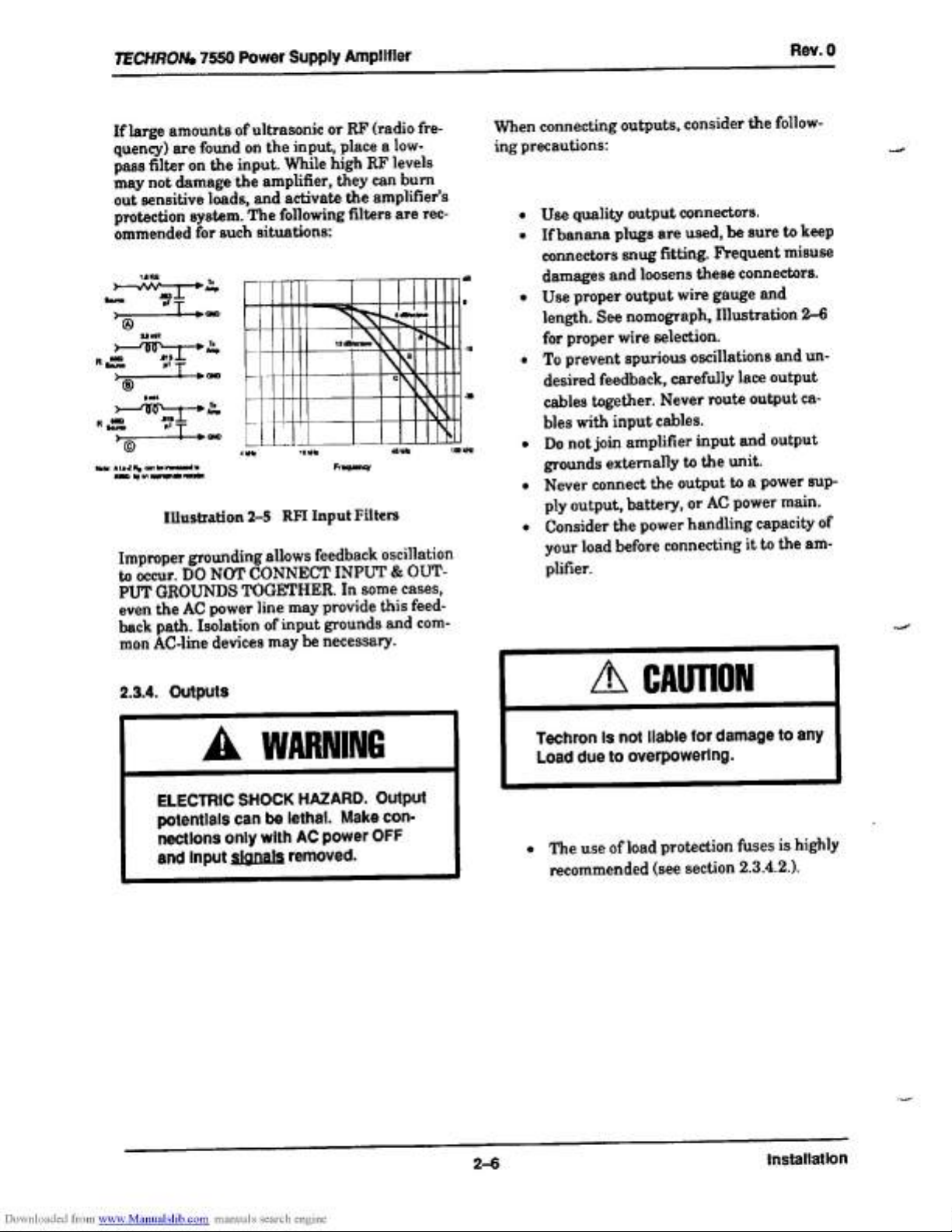
If
large
amounts
of
ultrasonic
or
RF
(radio
fre-
quency)
are
found
on
the
input,
place
a
low-
pass
filter
on
the
input.
While
high
RF
levels
may
not
damage
the
amplifier,
they
can
burn
out
sensitive
loads,
and
activate
the
amplifier’s
protection
system.
The
following
filters
are
rec-
ommended
for
such
situations:
bom
RO
ml
ire
—
wl
T
wo
Wat:
ALed
Mg
con
be
rarenead
w
RO
by
an
eppranate
resiotet.
Illustration
2-5
RFI
Input
Filters
Improper
grounding
allows
feedback
oscillation
to
occur.
DO
NOT
CONNECT
INPUT
&
OUT-
PUT
GROUNDS
TOGETHER.
In
some
cases,
even
the
AC
power
line
may
provide
this
feed-
back
path.
Isolation
of
input
grounds
and
com-
mon
AC-line
devices
may
be
necessary.
2.3.4.
Outputs
A
WARNING
ELECTRIC
SHOCK
HAZARD.
Output
potentials
can
be
lethal.
Make
con-
nections
only
with
AC
power
OFF
and
Input
signals
removed.
ns
When
connecting
outputs,
consider
the
follow-
ing
precautions:
—_
e¢
Use
quality
output
connectors.
If
banana
plugs
are
used,
be
sure
to
keep
connectors
snug
fitting.
Frequent
misuse
damages
and
loosens
these
connectors.
¢
Use
proper
output
wire
gauge
and
length.
See
nomograph,
Illustration
2-6
for
proper
wire
selection.
«
To
prevent
spurious
oscillations
and
un-
desired
feedback,
carefully
lace
output
cables
together.
Never
route
output
ca-
bles
with
input
cables.
*
Donot
join
amplifier
input
and
output
grounds
externally
to
the
unit.
¢
Never
connect
the
output
to
a
power
sup-
ply
output,
battery,
or
AC
power
main.
«
Consider
the
power
handling
capacity
of
your
load
before
connecting
it
to
the
am-
plifier.
Techron
is
not
liable
for
damage
to
any
Load
due
to
overpowering.
*
The
use
of
load
protection
fuses
is
highly
recommended
(see
section
2.3.4.2.).
Downloaded
from
www.Manualslib.com
manuals
search
engine
2-6
installation

TECHRONs:
7550
Power
Supply
Amplifier
Rev.
0
2.3.4.1.
Load
Wires
Use
cables
of
sufficient
gauge
(thickness)
for
the
length
used.
Otherwise,
power
is
lost
through
cable
heating
and
resistance.
Refer
to
the
nomograph
(Illustration
2-6)
below
for
rec-
ommended
wire
sizes.
Example
Shown:
AL
-
Sota
Ag
-
0.16
obs,
Cable
Length
=
50%;
anewer:
#12
wire
Illustration
2-6
Wire
Size
Nomograph
Use
the
nomograph
as
follows:
1.
Note
the
load
resistance
connected
to
each
channel
of
the
amplifier.
Mark
this
value
on
the
nomograph
“Load
Resis-
tance”
line.
2.
Note
the
“Reference
Point”
on
the
nomograph.
3.
Draw
a
pencil
line
through
these
two
points,
intersecting
the
“Source
Resis-
tance”
line.
4.
On
the
“2-Cond.
Cable”
line,
mark
the
length
of
cable
run.
5.
Draw
a
pencil
line
from
the
intersection
point
on
the
“Source
Resistance”
line
through
the
mark
on
the
“2-Cond.
Ca-
ble”
line.
6.
Where
the
pencil
line
intersects
the
“An-
nealed
Copper
Wire”
line
indicates
the
wire
gauge
required.
2.3.4.2.
Load
Protection
Loads
that
are
primarily
inductive
such
as
transformers
require
special
attention.
To
pre-
vent
large
low-frequency
currents
from
damag-
ing
the
transformer
(and
prevent
the
Model
7550
from
unnecessarily
activating
its
protec-
tion
system)
it
may
be
necessary
to
install
a
capacitor
in
series
with
the
load.
If
you
are
un-
sure
whether
this
is
necessary,
measure
the
DC
resistance
across
the
terminals
of
each
load
with
an
ohmmeter.
If
the
resistance
you
meas-
ure
is
less
than
3
ohms
either
add
the
following
parts
as
shown
in
Illustration
2-7
or
add
an
appropriate
high-pass
filter
or
contact
Techron
Engineering
for
further
information.
Place
an
external
non-polarized
capacitor
of
590
to
708
mfd
and
a
4
ohm
power
resistor
in
series
with
the
positive
(+)
lead
as
shown
be-
low:
dorm,
2W
FROM
AMP
INDUCTIVE
Load
OOOO
GNO
Mlustration
2-7
Inductive
Load
Protection
We
recommend
that
you
protect
your
loads
from
damage
resulting
from
excessive
power.
A
common
way
to
do
this
is
to
put
a
fuse
in
se-
ries
with
the
load.
Fuses
help
prevent
damage
due
to
prolonged
overload,
but
provide
essentially
no
protection
against
damage
from
large
transients.
To
minimize
this
problem,
use
high-speed
instru-
ment
fuses
such
as
the
Littlefuse™
361000
series.
If,
on
the
other
hand,
the
load
is
only
suscepti-
ble
to
damage
caused
by
overheating,
use
a
fuse
or
circuit
breaker
having
the
same
slow
thermal
response
as
the
load
itself
such
as
a
slow-blow
fuse.
Downloaded
from
www.Manualslib.com
manuals
search
engine
Se
ee
2-7
Installation

TECHRON,
7550
Power
Supply
Amplifier
Rev.
0
Illustration
2-8
is
a
nomograph
showing
what
size
fuse
to
use
according
to
the
impedance
and
peak
power
rating
of
the
load.
«
{
rrr
ryy
t
!
y
”
4
}
Mut
HHH
Liy
i
Example:
Z
=
3
ohms,
Peak
Power
=
750
|
Anwar.
Fuse
=
1.54
’
{yt
v
1
1
TPT
]
rTrt
LOAD
IMPEDANCE
(Z)
in
ohms
|
T
|
1
FUSE
in
ampe
(A)
Voi
yg
®
|
|
T
r
1
J
q
}
my
Illustration
2-8
Fuse
Selector
Nomograph
2.3.5.
AC
Power
Connect
Model
7550
to
proper
AC
current.
Supply
voltage
must
be
50
to
60Hz
and
no
more
than
10%
above
or
below
the
selected
line
volt-
age.
Failure
to
comply
with
these
frequency
limits
may
damage
the
unit
and
will
result
in
unreliable
operation.
Model
7550
may
be
operated
at
various
line
voltages.
The
serial
plate
indicates
factory
volt-
age
wiring.
The
tag
attached
to
the
line
cord
also
indicates
the
voltage
for
which
the
ampli-
fier
is
connected.
Five
standard
line-voltage
connections
are
of-
fered:
100,
120,
200,
220
and
240
VAC.
To
con-
vert
from
one
voltage
to
another,
see
Section
6.5.
Only
a
competent
technician
should
at-
tempt
to
convert
from
one
voltage
to
another.
Replace
the
FUSES
whenever
AC
voltage
con-
version
is
made
or
when
they
have
blown.
See
Section
3.4.
for
fuse
values
and
replacement
procedure.
The
amplifier
is
furnished
with
a
standard
three-wire
(grounded)
AC
plug.
Use
third
wire
ground
with
caution,
as
this
may
introduce
a
ground
loop
into
the
system.
If
a
ground
loop
is
present,
remove
ground
shorting
strap
on
the
back
panel.
See
[Illustration
3-2.
Three-to-two
wire
AC
plug
adapters
are
com-
mercially
available
for
adapting
to
a
two-wire
system
if
necessary.
Techron
assumes
no
Hlablility
whatsoever
for
ungrounded
operation
which
may
violate
UL
or
local
electrical
codes.
At
this
point,
installation
is
complete.
Read
the
next
section
to
familiarize
yourself
with
the
operation
and
functions
of
Model
7550.
Downloaded
from
www.Manualslib.com
manuals
search
engine
2-8
installation

TECHRONs,
7550
Power
Supply
Amplifier
Rev.
0
Section
3.
Operation
A.
WARNING
Never
operate
Model
7550
with
cover
panels
removed
because
you
could
be
ELECTROCUTED.
|
Refer
servicing
to
qualified
personnel.
3.1.
Operating
Precautions
Although
your
amplifier
is
well
protected
from
any
external
faults,
we
recommend
the
follow-
ing
precautions
be
taken
for
safe
operation:
1.
Operate
the
amplifier
from
AC
mains
of
not
more
than
10%
above
or
below
the
_
selected
line
voltage
and
within
the
specified
line
frequency
(50-60
Hz).
Fail-
ure
to
comply
with
these
limits
will
in-
validate
the
warranty.
2.
When
using
input
sources
of
uncertain
level
or
any
components
which
have
not
previously
been
used
with
your
ampli-
fier,
always
begin
with
the
level
controls
at
a
minimum
and
gradually
increase
them
while
monitoring
the
output.
3.
Operate
the
amplifier
with
the
correct
fuses
(F1I&F2
=
20
A,
F3
=
V2
A
for
100
or
120
VAC;
F1&F2=10A,F3=
V/4A
for
200,
220
or
240
VAC).
Turn
the
am-
plifier
off
i i
before
replacing
the
fuses.
4.
Do
not
expose
the
amplifier
to
corrosive
chemicals
such
as
soft
drinks,
lye,
salt
water,
etc.
5.
Do
not
tamper
with
the
circuitry.
Circuit
changes
made
by
unauthorized
person-
nel,
or
unauthorized
circuit
modifica-
tions,
will
invalidate
the
warranty.
AN
CAUTION
Do
not
operate
Model
7550
In a
small
sealed
chamber
of
any
kind.
Improper
operation
and
overheating
will
result.
3.2.
Functions
The
operating
functions
of
Model
7550
are
shown
and
explained
with
captioned
call-outs
on
the
following
two
pages
(Illustrations
3-1
and
3-2).
A
two-position
power
switch
and
an
amber
LED
power-on
indicator
are
located
on
the
front
panel.
Independent
level
controls
are
located
on
the
front
panel.
Both
level
controls
are
used
in
DUAL
mode,
but
only
the
Channel
1
control
should
be
used
in
MONO
mode.
They
are
used
to
adjust
the
desired
output
level.
There
are
red
JOC
(Input/Output
Comparator)
indicator
LEDs
located
in
the
middle
of
the
front
panel.
They
will
illuminate
whenever
the
distortion
specifications
of
the
amplifier
are
being
exceeded.
The
green
Signal
Presence
LEDs
are
located
on
the
front
panel
just
below
the
JOC
LEDs.
They
illuminate
any
time
there
is
more
than
0.6
Vrms
at
the
output
of
the
amplifier.
There
are
yellow
LEDs
just
below
the
green
LEDs.
They
illuminate
anytime
either
channel
is
in
the
standby
state.
(Continued
on
page
3-4)
3-1
Downloaded
from
www.Manualslib.com
manuals
search
engine
a
Operation

TECHRON,
7550
Power
Supply
Amplifler
Rev.
0
Illustration
3—1
Front
Panel
Functions
A.
Level!
The
volume
of
each
channel
is
independently
controlled
by
these
level
controls.
Each
con-
trol
has
thirty-one
detents
for
accurate
in-
crementation.
The
control
for
Channel
2
should
be
turned
down
(fully
counter
eloek-
wise)
and
not
used
when
operating
in
MONO
mode.
B.
10C®
Ared
Input/Output
Comparator
LED
is
pro-
vided
for
each
channel.
It
illuminates
when
distortion
of
any
kind
exceeds
0.05%.
It
also
acts
as
a
standby
indicator,
illuminating
when
in
STANDBY
mode.
It
is
normal
for
the
JOC
indicators
to
illuminate
briefly
when
the
amplifier
is
turned
on
or
off.
C.
Signal
Presence
Agreen
LED
is
provided
for
each
channel
to
indicate
when
a
signal
is
present.
Normally
they
will
either
flash
or
stay
illuminated
(de-
pending
on
the
signal
level).
If
the
level
is
very
low
they
may
not
illuminate
at
all.
D.
Standby
Indicators
Yellow
LEDs
illuminate
when
either
chan-
nel
is
in
the
standby
state.
This
will
occur
when
using
the
DELAY
feature.
E.
Power
Indicator
An
amber
LED
will
illuminate
whenever
the
Model
7550
is
switched
on.
F.
Power
This
two-position
switch
turns
the
amplifier
ON
or
OFF.
At
turn-on,
the
output
is
muted
(placed
in
STANDBY
mode)
for
about
four
seconds
to
protect
your
load
from
start-up
transients.
(This
feature
can
be
disabled
with
the
Delay
Switch
on
the
back
panel.)
G.
Fan
Intake
The
7550
has
a
dust
filter
on
the
air
intake
to
the
cooling
system.
The
filter
may
be
re-
moved
for
cleaning.
3-2
Downloaded
from
www.Manualslib.com
manuals
search
engine
Operation

TECHRONz
7550
Power
Supply
Amplifier
Pw
een
La
a0)
Wee
Ocha
Poke
Seas
PUN
La
Masel
Ce
el
tatty
Leer
3
x
Xo)
PORN
REO
RACEe
Seertarrceh
unicef
Gir
ane
r
ret
cy
A)
sol
Rev.
0
N
oO
Illustration
3-2
Back
Panel
Functions
H.
Ground
Barrier
Strip
Isolation
of
chassis
ground
from
signal
ground
is
easily
accomplished
by
removing
the
shorting
strap
from
this
terminal
strip.
This
may
help
remove
any
hum
problems
caused
by
“ground
loops.”
(The
grounds
are
always
connected
in-
ternally
with
a
resistance
of
2.7
ohms.)
I.
Power
Cord
A
standard
three-wire
(grounded)
AC
cord
is
provided.
Plug
into
the
specified
AC
power
(see
Section
2.3.5.).
J.
input
BNC
Jacks
An
unbalanced
BNC
jack
is
provided
at
the
in-
put
of
each
channel.
Do
not use
the
input
jack
for
Channel
2
when
in
MONO
mode.
K.
Dual-Mono
Switch
Slide
this
switch
left
for
DUAL
mode
and
right
for
MONO
mode.
In
MONO
mode
the
input
and
level
control
for
Channel
2
should
not
be
used.
>
Only
balanced
(ungrounded)
loads
should
be
connected
to
the
output
jacks.
(See
Section
2.3.)
L.
Low
Frequency
Protect
Switch
Engaging
this
switch
causes
the
unit
to
cy-
cle
through
the
“STANDBY”
mode
if
low
fre-
quency
(DC-10
Hz)
appears
at
the
output.
M.
Delay
Switch
This
switch
activates
a
four-second
delay
in
the
transition
state
from
“turn-on”
to
high-
voltage
power
supplies
on.
N.
Output
Connectors
Banana
jacks
are
provided
at
the
output
of
each
channel.
Only
the
two
top
jacks
(red)
are
used
in
MONO
mode
since
both
chan-
nels
are
bridged.
O.
Balanced
Input
Module
Socket
This
11-pin
radial
socket
is
provided
for
one
of
two
optional
balanced
input
modules
(75A06
or
75A07).
The
75A07
uses
a
trans-
former
to
balance
the
inputs
while
the
75A06
uses
active
circuitry.
If
one
of
these
modules
is
used,
the
unbalanced
inputs
should
not
be
used.
3-3
Downloaded
from
yww.Manualslib.com
manuals
search
engine
Operation

TECHRONz
7550
Power
Supply
Amplifier
Rev.0
On
the
back
panel
the
Model
7550
has
a
dust
filter
on
the
air
intake
to
the
cooling
system.
The
filter
may
be
removed
for
cleaning.
To
isolate
chassis
ground
from
signal
ground,
you
can
use
the
back
panel
Ground
Barrier
Strip
by
removing
the
shorting
strap.
Grounds
are
always
connected
internally
with
the
resis-
tance
of
2.7
ohms.
The
two
BNC
connectors
on
the
back
panel
pro-
vide
for
easy
connection
and
disconnection
of
input
signals.
Switch
between
DUAL
and
MONO
mode
with
the
Dual/Mono
switch
located
on
the
back
panel.
Below
this
switch,
is
the
Low
Frequency
Pro-
tect
Switch.
Engaging
it
causes
the
unit
to
cy-
cle
through
the
“STANDBY”
mode
when
low
frequency
(DC-10
Hz)
appears
at
the
output.
The
next
switch
is
the
Delay
Switch.
This
switch
activates
a
four-second
delay
in
the
transition
state
from
“turn-on”
to
high-voltage
power
supplies
on.
Model
7550
includes
two
standard
MDP
“dual
banana’
type
output
jacks
on
the
back
panel.
In
DUAL
channel
operation,
use
two
dual
banana
plugs
connected
vertically.
Use
one
dual
ba-
nana
plug
connected
horizontally
to
both
“hot”
(+)
terminals
in
MONO
operation.
The
back
panel
also
includes
an
11-pin
acces-
sory
socket.
Some
accessories
are
described
in
Section
6.
Contact
Techron
engineering
for
any
other
accessories
available.
Each
accessory
comes
with
its
own
documentation
for
installa-
tion
and
use.
Also
located
on
the
back
panel
is
a
heavy
duty
three-wire
(grounded)
AC
line
cord.
3.3.
Protection
Techron
power
amplifiers
are
widely
known
for
~
their
quality
construction,
high
reliability
and
extensive
internal
protection
circuitry.
The
Model
7550
is
no
exception.
It
is
protected
against
all
the
common
hazards
which
plague
high-powered
amplifiers
such
as:
e
input
overload
damage;
e
shorted,
open
and
mismatched
loads
(oad
impedance
too
low);
chain
destruction
phenomena;
high
frequency
overload
blowups;
excessive
temperature;
and,
overloaded
power
supplies.
eeee
The
input
stage
is
protected
against
excessive
input
signal
level
(overdrive)
by
a
series-limit-
ing
resistor.
Protection
against
shorted
and
low
impedance
loads
is
provided
by
a
fast-acting
limiter
circuit
which
instantaneously
limits
the
output
power
to
a
maximum
safe
stress
value.
It
functions
automatically
as
a
current
limiter
at
audio
frequencies
whose
current
limiting
threshold
is
dependent
on
the
history
of
the
output
signal.
Increased
output
current
causes
the
threshold
to
increase,
however,
the
no-signal
threshold
is
high
enough
to
allow
tone
bursting
(even
into
4
ohms)
without
premature
limiting.
Since
the
limiter
has
no
instantaneous
re-
sponse
to
output
voltage,
“flyback”
transients
do
not
appear
in
the
output
when
limiting
oc-
curs
on
inductive
loads.
(“Flyback”
transients
are
a
normal
by-product
of
VI
limiting
with
an
inductive
load.)
Because
the
current
limiter
of
the
Model
7550
will
not yield
to
the
constant
current
demands
of
an
inductive
load,
it
is
immune
to
“flyback”
distortion.
Downloaded
from
www.Manualslib.com
manuals
search
engine
Operation
Other manuals for 7550
1
Table of contents
Other Techron Amplifier manuals


