TechToyS SSD1963 Eval Rev2A User manual

User’s Guide of SSD1963 Eval Rev2A
Doc. version 1.0b 8
h
Feb 2010 Page
1
SSD1963 Eval Rev2A
User’s Guide
TechToys Company
Uni 1807, Pacific Plaza, 410 Des Voeux Road
Wes , Hong Kong
Tel: 852-28576267
Fax: 852-28576216
Web si e: www.TechToys.com.hk

User’s Guide of SSD1963 Eval Rev2A
Doc. version 1.0b 8
h
Feb 2010 Page
2
1. Introduction
SSD1963 Eval Rev2A is a developmen board for Solomon SSD1963 display
con roller which provides 1,215K by e frame buffer wi h parallel MCU in erfaces
for RAM-less LCD panels up o 864x480 a 24-bi per pixel resolu ion. Wi h linear
vol age regula ors, LED backligh circui s, and FPC connec ors for ouch panels
all buil -in, users are provided wi h all necessary circui ry for es ing TFT panels
of differen size wi h heir own choice of hos microcon rollers.
A represen a ion of he board layou is shown in Figure 1.1. The board includes
hese key fea ures, as indica ed in he diagram:
1
2
3
4
5
igure 1.1 Board layout
User’s Guide of SSD1963 Eval Rev2A
Doc. version 1.0b 8
h
Feb 2010 Page
3
1. Vol age regula ors for 5V, 3.3V, and 1.2V driving LED backligh (5V), in erface
supply power for LCD and digi al I/O (3.3V), as well as he core supply
vol age (1.2V) for SSD1963.
2. Four FPC connec ors (J1~J4) for differen LCD panels. There are dozens of
TFT pin-ou defini ions as here is no indus rial s andard for his. Only four
connec ors will no cover all of he TFT in erfaces bu a leas four panel sizes
have been verified including 3.5”, 4.3”, 5.6”, and 7” TFT panels on his
evalua ion board.
3. Two FPC connec ors (J5, J6) of bo om con ac for ouch panels. Some panels
have individual FPC for Touch Panel while o hers have Touch Panel signal
in egra ed wi h da a bus on a single FPC. These FPC connec ors of 0.5mm and
1.00mm pi ch provide a convenien access o Touch Panel signals in case he
signals are separa ed from he da a-bus-FPC. This is very common for large
panel size like 5.6” and 7” panels.
4. Two LED backligh circui s for
a. High vol age 20mA cons an curren whi e LED driver (CAT4237, On
Semiconduc or Inc). The CAT4237 is a DC/DC s ep-up conver er ha
delivers an accura e cons an curren source driving 6 o 8 whi e LEDs
in series. Ou pu of CAT4237 is rou ed o J3 and J4 for 4.3” and 3.5”
panels, respec ively.
b. 22V high curren boos whi e LED driver (CAT4139, On
Semiconduc or Inc). The CAT4139 is a DC/DC s ep-up conver er ha
delivers an accura e cons an curren ideal for driving parallel s rings
of up o five whi e LEDs in series or up o 22V. TFT panels of larger
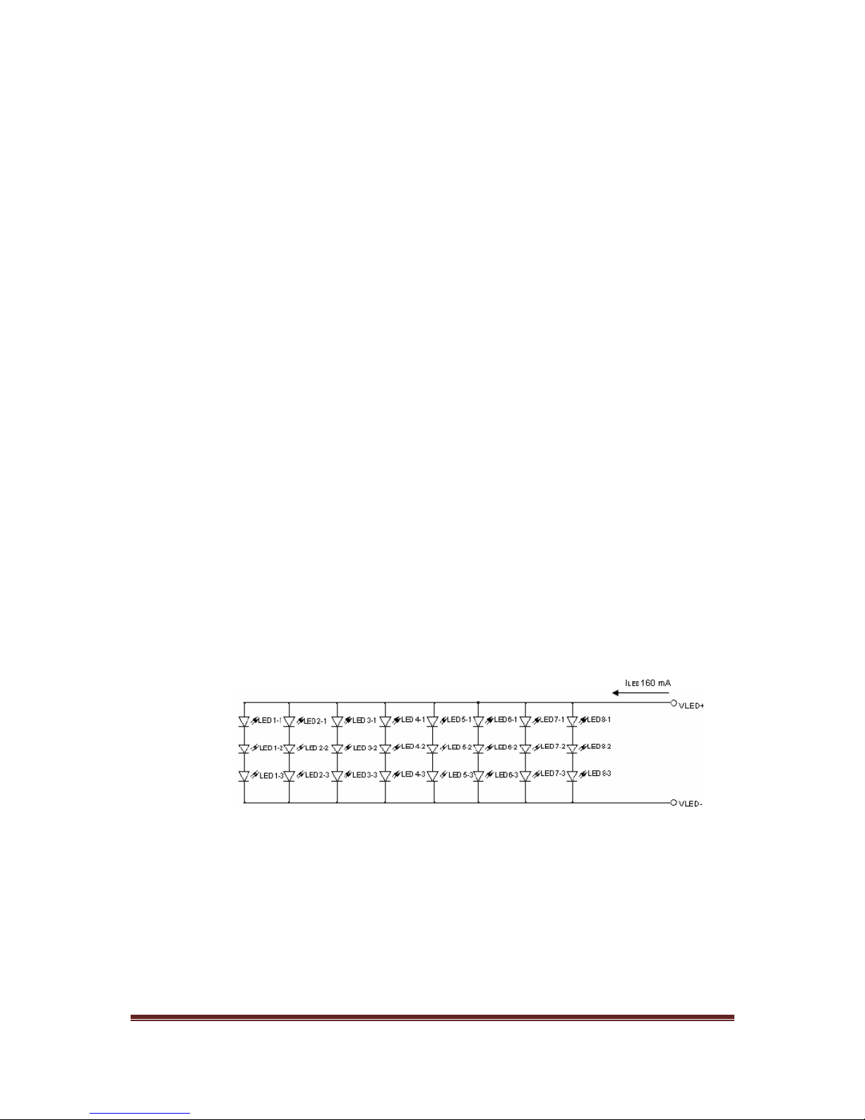
size (>5.6”) require a lo more whi e LEDs han small panels. Le ’s ake
an example from our 7” TFT panel. The whi e LEDs are organized in 8
parallel groups of 3 LEDs in series as shown in Figure 1.2. The curren
required is 160mA (20mA x8) and he vol age requiremen is 9.9V.
The CAT4139 is capable of delivering 750mA wi h vol age as high as
22V under a single 5V DC supply. Ou pu of CAT4139 is rou ed o he
high vol age connec or J7.
igure 1.2 Backlight configuration of 7” T T panel
5. S andard 40-pin 2.54mm box header for MCU in erfaces. This box header
provides a direc s ack wi h our PIC24/32 Eval RevC2 board via a fla cable
which is included wi h every board SSD1963 Eval Rev2A sold.

User’s Guide of SSD1963 Eval Rev2A
Doc. version 1.0b 8
h
Feb 2010 Page
4
2. Hardware
Hardware used in his manual includes he following componen s
1. Evalua ion board for Microchip 100-Pin General Purpose MCU:
Op ion wi h PIC32MX360F512L
Part number: PIC24/32 EVAL Rev2A – option PIC32MX360 512L
2. Evalua ion ki for Solomon SSD1963 Display Con roller
Part number: SSD1963 Eval Rev 2A
3. 3.5" QVGA color TFT-LCD module wi h Touch Panel
Part number: LVC75Z779V1S
4. 4.3" WQVGA color TFT-LCD module wi h Touch Panel
Part number: TY430T T480272Rev03
5. 7" WVGA 262k color TFT-LCD module wi h Touch Panel
Part number: TY700T T800480Rev01
3. Software
Several demo programs are provided for quali y assurance. These programs
have been developed under Microchip Graphics Library Version v2.00 wi h a low
level driver for SSD1963 developed by us.
However, I must emphasize that, it is not restricted to use Microchip’s
microcontrollers to interface the SSD1963. Any microcon roller or processor
ha is able o genera e he required con rol signal (CS#, DC, RD#, WR#, and
D[23:0]) will be able o drive SSD1963. There are few Graphical Libraries such as:
• Luminary (now belongs o Texas Ins rumen s) Micro Graphics Library
o h p://www.luminarymicro.com/produc s/s ellaris_graphics_library.h ml
• Renesas Graphics Library
o h p://america.renesas.com/fmwk.jsp?cn =sw_lib_child.h m&fp=/produc s
/mpumcu/h8_family/h8_lcd/child_folder/& i le=Graphic%20Anima ion%2
0Sof ware
• PEG embedded Graphical User In erface
o h p://swellsof ware.com/produc s/
• Easy GUI by IBIS Solu ion ApS
o h p://www.easygui.com
• emWin supplied by Segger Microcon roller GmbH & Co. KG
o www.segger.com
Some of hese libraries are free as long as you would use heir produc s while he
o hers provide por o various MCUs a a cer ain cos . Users may selec heir hos
and decide which GUI is he bes for he applica ion. Microchip Graphics Library
has been chosen because i is free as long as he library will be embedded in
Microchip produc s.

User’s Guide of SSD1963 Eval Rev2A
Doc. version 1.0b 8
h
Feb 2010 Page
5
4. Installing different LCD Panels
4.1 Ins alling 7” TFT panel TY700TFT800480
The TFT panel (model # TY700TFT800480Rev01) is a WVGA 262k color LCD
module. LED backligh and Touch Panel are connec ed by individual connec ors.
Including he FPC for da a, here are hree connec ors o be ins alled. Turning o
he bo om side of he LCD module, we will see a 40-pin bo om con ac FPC
connec or as shown in Figure 4.1. Mos likely an 18cm flex cable has been
ins alled for you. If no , please connec i wi h he silver con ac s of he flex cable
downwards. Figure 4.2 illus ra es how he 7” TFT panel is connec ed.
igure 4.1 Bottom side of 7” T T panel TY700T T800480
igure 4.2 Connect a 7” T T panel to SSD1963 Eval Kit
User’s Guide of SSD1963 Eval Rev2A
Doc. version 1.0b 8
h
Feb 2010 Page
6
Impor an message: There are hree 40-pin FPC connec ors onboard. They are J1,
J2, and J3. They come from he same manufac urer of he same model bu hey
have been designed o connec differen TFT panels. Don’ confuse hem;
o herwise, your TFT panel may be damaged.
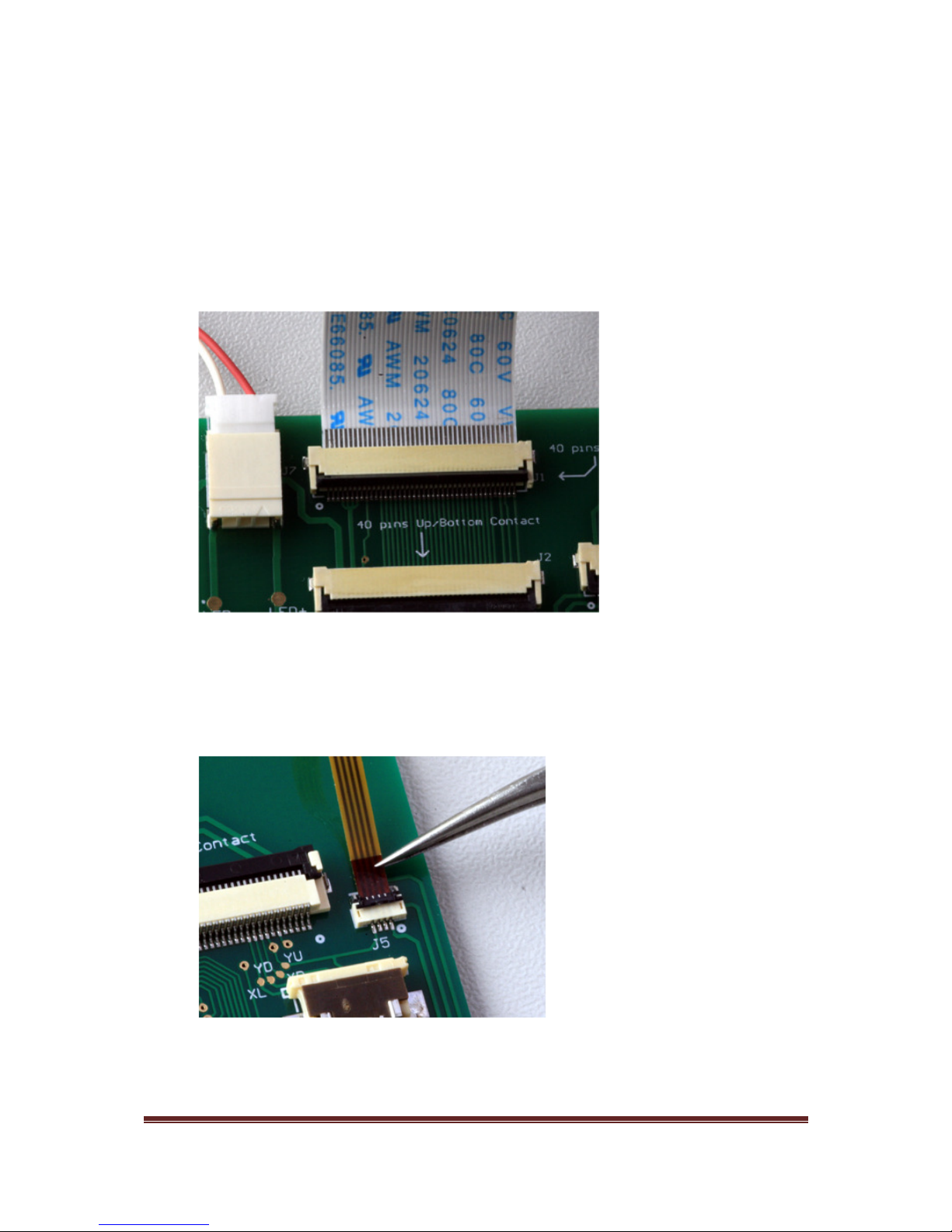
Connec he 18cm flex cable of TY700TFT800480 o only J1! This ime, silver
con ac s of he flex cable should be facing upwards. Then, J7 connec ion can be
made for backligh . Connec or J7 is a high vol age connec or which is wired o
CAT4139 for a driving curren as high as 160mA. Figure 4.3 illus ra es he
connec ions.
Finally, connec he FPC for Touch Panel o J5 as shown in Figure 4.4. Use a
weezers o handle his par close o he ip (don’ clip on he sof cable par .)
Push gen ly he FPC in o J5 wi h gold con ac s down. Please do i slowly wi h
grea care because his FPC is very fragile.
igure 4.3 Connection of J1 and J7 for 7” T T panel (TY700T T800480)
igure 4.4 Connect Touch Panel PC to J5 by holding the tip of the PC

User’s Guide of SSD1963 Eval Rev2A
Doc. version 1.0b 8
h
Feb 2010 Page
7
4.2 Ins alling he 4.3” TFT panel TY430TFT480272
Ins alla ion of 4.3” TFT panel is much easier because he LED backligh , da a, and
Touch Panel signals are all in egra ed on a single 40-pin FPC. Connec ion is made
o J3 as shown in Figure 4.5.
igure 4.5 Connect 4.3” T T panel TY430T T480272 to J3
4.3 Ins alling he 3.5” TFT panel LVC75Z779V1S
Ins alla ion of 3.5” TFT panel is made o J4 on SSD1963 Eval Ki as shown in
Figure 4.6. This is he only 54-pin connec or onboard wi h bo om con ac . No
mis ake can be made for his.
igure 4.6 Connect 3.5” panel LVC75Z779V1S to J4

User’s Guide of SSD1963 Eval Rev2A
Doc. version 1.0b 8
h
Feb 2010 Page
8
5. Connection to MCU
The MCU in erface is rou ed on a s andard 2x20 2.54mm box header. Figure
5.1 shows an ex rac from he schema ic.
igure 5.1 Schematic of the MCU interface
Impor an message:
a. VDD = 3.3V from he vol age regula or AMS1117-3.3V onboard
b. EXT_VIN = Ex ernal vol age inpu from an ex ernal source applied a DC
inpu jack J1P. Therefore, if you have 7.5V DC applied o J1P, EXT_VIN a
pin 38 would be a 7.5V.
There are hree label prefixes:
a. SSD_xxx : prefix for SSD1963 display con roller
b. EVK_xxx : prefix for PIC24/32 Eval RevC2 demo board (hyperlink)
h p://www. ech oys.com.hk/PIC_boards/PIC24-Eval-C/PIC24-Eval-RevC.h m
c. TP_xxx : prefix for Touch panel
The EVK prefixes are used o indica e how our PIC24/32 Eval Rev2C board is
connec ed o SSD_D[15:0] wi h various con rol signals. Figure 5.2 shows he
wiring o PIC24/32 Eval RevC2 board. A fla cable is provided for every SSD1963
Eval ki sold.

User’s Guide of SSD1963 Eval Rev2A
Doc. version 1.0b 8
h
Feb 2010 Page
9
The choice of 2.54mm box header allows you o connec he SSD1963 Eval Ki o
any microcon roller or evalua ion pla form.
Figure 5.3 shows he scenario when SSD1963 Eval Ki is hooked up wi h an
A mel SAM AT91 mcu ki by jumper cables. Jumper cable se is also available
from our s ore a he following hyperlink:
h p://www. ech oys.com.hk/Componen s/JumperCable/JumperCable.h m
igure 5.3 Connection to SSD1963 Eval kit can be made via 2.54mm jumper cables
igure 5.2 Connection to PIC24/32 Eval RevC2 platform

User’s Guide of SSD1963 Eval Rev2A
Doc. version 1.0b 8
h
Feb 2010 Page
10
6. Installing the hardware
Figure 6.1 shows he block diagram of he sys em.
igure 6.1 Block diagram of SSD1963 Eval Rev2A
The board is powered from an ex ernal 7~9V DC wi h pin posi ive. This vol age is
regula ed o 5V DC a U1P (AMS1117-5V) for wo LED backligh circui s, CAT4237 and
CAT4139 and fur her s epped down o 3.3V for SSD1963 and TFT panels.
If he hos PIC24/32 Eval board is used, power supply a 3.3V will be sourced from he
2.54mm in erface header. Figure 6.2 illus ra es he wiring wi h pa h of power supply.
5V DC-DC
conver er (U1P)
3.3V DC
-
DC conver er (U2
P)
1.2V DC-DC
conver er (U2)
SSD1963
2.54mm box header (JP1E) for SSD_D0:23, CS#, e c
EXT_VIN (7.5V), VDD (3.3V), and GND
FPC(s)
LED backligh DC
-
DC
EXT_VIN
(7.5V)
VDD o hos
User’s Guide of SSD1963 Eval Rev2A
Doc. version 1.0b 8
h
Feb 2010 Page
11
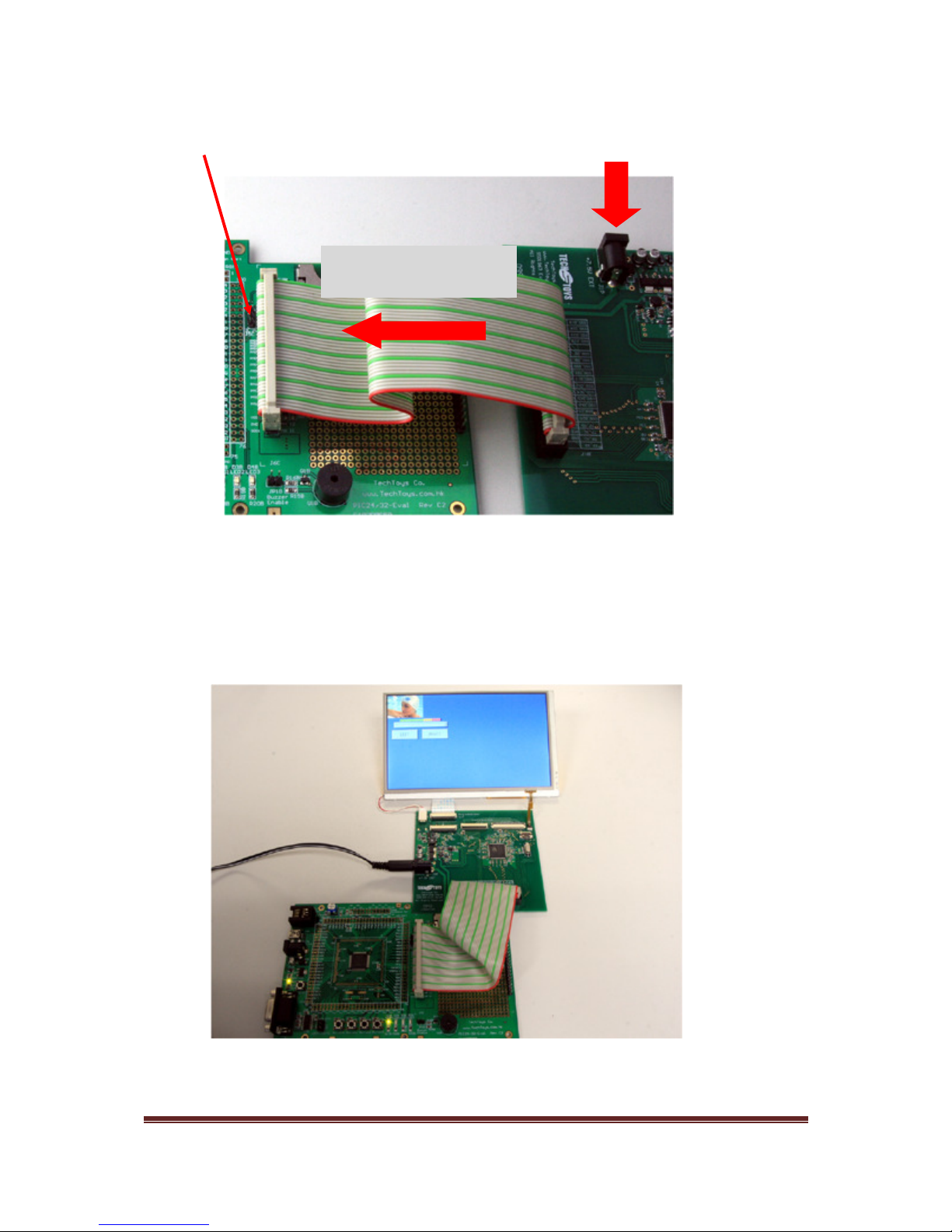
Once we have go every hing connec ed, apply 7.5V DC o J1P on SSD1963 Eval Ki .
Figure 6.3 shows he se up wi h a 7” TFT panel and PIC32MX360F512L MCU op ion
running.
Ext 7.5
-
9V DC applied
Leave J5C open
igure 6
.2
Power up the board with an external voltage applied at J1P
igure 6.3 PIC24/32 Eval with PIC32MX running Microchip Graphic
Library Version 2.00 on a 7” T T
3.3V DC from header
to MCU

User’s Guide of SSD1963 Eval Rev2A
Doc. version 1.0b 8
h
Feb 2010 Page
12
7. Running the Program
7.1 S ar ing he Demo Projec
A ime of wri ing, six projec s are provided for ou -of- he-box
demons ra ion. These demos have been modified from he original demos
provided by Microchip Graphics Library v2.00
1
.
Developmen Environmen :
• Microchip MPLAB version 8.10 or la er
• C32 compiler version 1.05 or la er
• Microchip Graphics Library version 2.00
The source code is available for download s ar ing from Doc 04 under our
produc web si e a his hyperlink.
h p://www. ech oys.com.hk/Displays/SSD1963EvalRev2A/SSD1963 Eval Board Rev2A.h m
1
h p://www.microchip.com/s ellen /idcplg?IdcService=SS_GET_PAGE&nodeId=2608¶m=en532067
igure 7.1 Projects based on Microchip Graphics Library v2.00

User’s Guide of SSD1963 Eval Rev2A
Doc. version 1.0b 8
h
Feb 2010 Page
13
Table below makes a summary:
Doc # Descrip ion Func ions o demo
04 How o use widge s in Microchip
Graphics Library
This projec con ains he source code for
Microchip Graphics Library v2.00.
Cus om driver for SSD1963 under he pa h
.\Microchip\Graphics\Drivers\ssd1963.c &
.\Microchip\Include\Graphics\ssd1963.h
The original Microchip App. No e is AN1136.
Basically his demo makes an in roduc ion o
widge applica ion via wo push bu ons and a
slide bar as simple con rol.
Users should s ar from his projec because he
ssd1963 driver and Microchip Graphics Library
are included only in his projec .
05 Graphics Primi ive Layer Demo Simple primi ive graphics prin ing such as circle,
arc, rec angle, as well as bi map display from
flash is demons ra ed.
06 Graphics AN1246 This projec demons ra es he Tex En ry widge
for a 4x4 keypad wi h Touch Panel.
07 Graphics Objec Layer Demo An all-rounded demo including:
1. Bu ons
2. Checkbox
3. Radio bu ons
4. S a ic Tex display
5. Slider
6. Progress bar
7. Lis box
8. Edi box as a elephone num pad
9. Round me ers
10. Dial
11. Simple anima ion
12. Cus om con rol
13. Signa ure like doing an UPS receip
14. Graph plo ing wi h ADC inpu
15. Simula ed ECG
08 Display JPEG/BMP/GIF images
from an SD Card
Images read from an SD card (<2GB) and go
displayed on 7”, 4.3”, or 3.5” TFT panels!
09 Graphics Mul iApp Demo This demo makes a swee summary of all demos
from Doc 07 plus:
1. Using icons as he choice of demo like a
mobile phone
2. Mul i-language suppor
3. A simple chess game
4. Real- ime-clock
5. Bar graphs

User’s Guide of SSD1963 Eval Rev2A
Doc. version 1.0b 8
h
Feb 2010 Page
14
7.2 Procedure
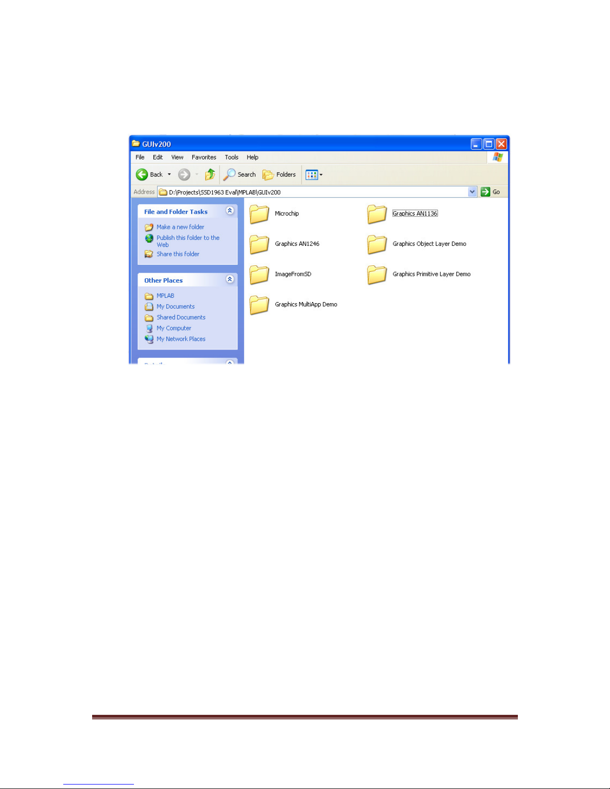
Download and uncompress he file GUIv200.rar o any loca ion you find
convenien . For my case, i under
D \Projects\SSD1963 Eval\MPLAB\GUIv200\Graphics AN1136\AN1136Demo PIC32.mcp.
Two folders, namely \Microchip and \Graphics AN1136 as shown in Figure 7.2
will be ins alled. The folder \Microchip con ains he source code for he graphics
library and an individual projec is loca ed under \Graphics AN1136 folder.
The \Microchip folder is ins alled only once for version con rol.
igure
7.2
Microchip Graphics Library source folder and an application AN1136
User’s Guide of SSD1963 Eval Rev2A
Doc. version 1.0b 8
h
Feb 2010 Page
15
By con inuing wi h download and uncompress from Doc 05 o Doc 09, he
following folder hierarchy will be seen (Figure 7.3). Make sure all projec folders
are loca ed under he same pa h as he Microchip folder; o herwise, compila ion
will fail due o missing source code loca ion for individual projec .
Firs , launch MPLAB and browse o your working direc ory. Open he projec file
AN1136Demo PIC32 (or xxx PIC32.mcp) for PIC32.
Make sure no missing file message is crea ed. Also make sure he correc MCU
has been selec ed under Configure→Selec Device o make sure he MCU
PIC32MX360F512L has been chosen.
igure
7.3
older hierarchy after finishing all downloads

User’s Guide of SSD1963 Eval Rev2A
Doc. version 1.0b 8
h
Feb 2010 Page
16
Under he Projec Workspace a he lef panel, double-click on HardwareProfile.h
for panel selec ion. Selec he panel you wan o use by leaving only one op ion
under __PIC32MX__ sec ion.
Figure 7.4 gives an example for he hardware pla form PIC24/32 EVAL Rev2C
(_PIC_EVK_V2C_), wi h 16-bi PMP in erface (_16PMP), for SSD1963 (_SSD1963),
and 7” TFT Panel (_TY700).
Un
Finally, under Project, selec Build All o make sure he projec can be compiled
wi hou any problem. You are now ready o play wi h he demo.
igure
7.4
Under HardwareProfile.h select the panel to use


