DESCRIPTI N
WP10EX stainless steel Pressurized Washer System ith integral solenoid valve has been developed to be used ith
CCTV cameras in industrial, marine and highly corrosive environments. The asher system supplied pairs preferably ith
Tecnovideo camera housings or alternatively ith housings hich haven't asher facility. The fluid tank is a 10 litre
manually pressurized unit ith built in pressure gauge. Solenoid's control voltage to be connected to the solenoid's
terminal box through suitable po er cables. An AISI316L stainless steel compact cabinet protects the unit from the
environmental agents.
M DELS
WP10EXe/24 24 VUC supply voltage. EX II 2G Ex e mb IIC Gb T4, II 2D Ex t IIIC Db IP67 T=135°C
WP10EXe/110 110 V~ supply voltage. EX II 2G Ex e mb IIC Gb T4, II 2D Ex t IIIC Db IP67 T=135°C
WP10EXe/230 230 V~ supply voltage. EX II 2G Ex e mb IIC Gb T4, II 2D Ex t IIIC Db IP67 T=135°C
WP10EXd/24
1
24 V~ supply voltage. EX II 2G Ex d IIC Gb T6, II 2D Ex tb IIIC Db IP66/67
WP10EXd/110
1
110 V~ supply voltage. EX II 2G Ex d IIC Gb T6, II 2D Ex tb IIIC Db IP66/67
WP10EXd/230
1
230 V~ supply voltage. EX II 2G Ex d IIC Gb T6, II 2D Ex tb IIIC Db IP66/67
1
½” NPT Nickel-plated brass cable gland (EX II 2 G E d IIC, II 2 D E tD IP68) for armoured cable (O.D. 8,5 to 16mm, I.D. 6 to 12mm) included.
CERTIFICATI NS
Ingress Protection(EN 60529) Solenoid valve: IP67 (WP10EXe models) / IP66/IP67 (WP10EXd models)
Cabinet: not rated
Rating (WP10EXe models) II 2G Ex e mb IIC Gb T4 / II 2D Ex t IIIC Db IP67
Rating (WP10EXd models) II 2G Ex d IIC Gb T6 / II 2D Ex tb IIIC Db IP66/67
EMC EN 61000-6-3:2007; EN 50130-4:1995 + A1:1998 + A2:2003
LVD EN 60950-1:2006 + A11:2009
RoHS 2011/65/EU
WEEE 2012/19/EU
PRELIMINARY REMARKS
i
Prior to installation and operation, read carefully all instructions in this manual and in the solenoid valve installation
manual. Heed all arnings.
Unpack this equipment and handle it carefully. If the package appears to be damaged, notify the shipper immediately.
Use the original packaging to transport the unit. Disconnect po er supply before moving it. In case of returning the
equipment, the original packaging must be used.
Make sure that the
installation surface can support at least four times the eight of the unit in normal operating
conditions. In case of excessive external stress (e.g. vibration, strong inds or impact), the equipment may need additional
means of protection.
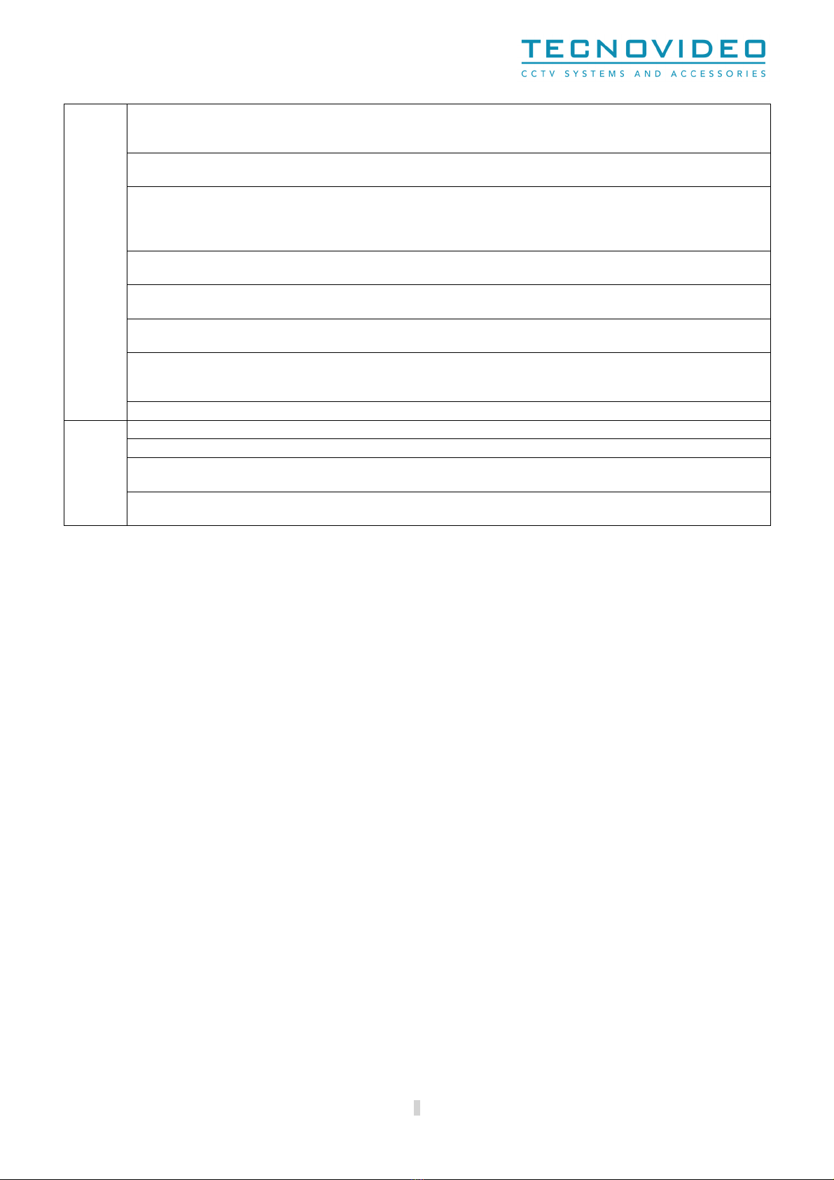
Proper stainless steel hard are should be carefully chosen to fasten the unit to the surfaces.
Use caution hen lifting and assembling the unit. It is recommended that non-
slip protective gloves be orn during
installation. The unit could bear sharp edges.
Keep the unit empty until the end of the installation.
The unit is intended to be used ith ater or ith ater solutions: denser mixtures could obstruct the nozzle. If the
solution used has residual, it must be filtered before use.
Do not use inflammabl
e liquids, hydrogen peroxide (nor similar
substances that give off oxygen), corrosive substances, liquids containing ammonia, solvents and liquids containing
solvents, viscous or greasy liquids, liquids that form residues (dyes and greases).
The safety valve must not be bypassed or made inoperative.
Observe the legal requirements of your country for accident prevention and check the tank regularly.
Stainless steel reservoir: keep the O-
rings, the safety valve and the internal of the tank clean. When opening/closing the
reservoir, pay attention to the correct placement of the O-rings in their seatings.
Use appropriate tools for the purpose. The part
icular nature of the site here the device is to be installed may require
special tools for installation.
Tightening/loosing the scre s using automatic tools such as drill drivers may result in
damaged threads.
3